Stegmaier-Haupt TV 6.2 User manual

_____________________________________________________________________________________
Manual
Transistor Servo Drive
TV 6.2
for DC Motors
TV 6.2
Version
0506
Stegmaier-Haupt GmbH
Industrieelektronik-Servoantriebstechnik
Untere Röte 5
D-6 231 Rauenberg
Tel.: 06222-61021
Fax: 06222-64 88
Email: info@stegmaier-haupt.de
Http: // www.stegmaier-haupt.de
Stegmaier-Haupt GmbH Industrieelektronik
____________________________________________________________________________________________

Transistor Servo-Drive TV 6.2
2
Contents Titel Page
1.Basic Information Safety advice 3
Standards and Guidelines 3
General information 4
Technical Data 5
eatures 6
Applications 6
2. Electrical installation Adjustments 7
LED displays 8
Signal test points 8
Terminal connections and connectors 9
Test point jack 9
Option switches 10
. Mech. installation ront panel 6HE 11
Components 12
Rear panel 6HE 14
Build 15
Dimension 16
4. Adjustments Connection - compact device 17
Connection - multiple-axes combination 17
Power connection 18
Ballast circuit 19
Output stage 19
Power section watchdog 20
Enable 21
Command value 22
Command value current 23
Current limiting 24
Actual value 25
Signals- BTB,
outputs, tacho fault, overload,
over-temperature, stationary 26
Adjustments 27
P-component 28
I-component 28
Tacho control 29
Armature voltage control 29
Diagram - control settings 30
Diagram - actual value differentiation 31
Peak current 31
Commutation limit 32
5. Commissioning 33, 34
6. Protocol 35, 36
7. Guarantee 37
8. Circuit diagrams 39-42
TV6.2 3
1 Basic Information
Electronic Equipment is not fault proof. This fact should be borne in mind for all
possible operating conditions.
Before installation or commissioning begins, this manual must be thoroughly
read and understood by the technical staff involved.
If any uncertainty arises, the Manufacturer or Dealer should be contacted.
Servo-Drive TV6.2 devices are Power Electric parts used for regulating energy
flow. Protection rating IP00.
Standards and Guidelines:
The device and it’s associated components can only be installed and switched
on where the local laws and technical standards have been strictly adhered to:
EU-Guidelines 89/392/EWG, 84/528/EWG, 86/663/EWG, 72/23/EWG
EN60204, EN50178, EN60439-1, EN60146, EN61800-3
- IEC/UL IEC364, IEC 664, UL508C, UL840
- VDE-regulations VDE100, VDE110, VDE160
- TÜV-regulations
- Regulations of Professional and Occupational bodies: VGB4
The user must ensure that in the event of :
- device failure
- incorrect operation
- loss of regulation or control
the axis will be safely de-activated.
It must also be ensured that the machine or equipment be fitted with device in-
dependent monitoring and safety features.
Setting Adjustments
- should only be carried out by suitably trained personnel
- should only be carried out in accordance with Health and Safety guidelines
Installation
- should only be carried out when all Voltages have been removed.
QS
Test results are archived with the device serial number by the manufacturer.
CE
The device adheres to the following: Guideline EU 89/336/EWG. EMV standards
EN61000-2 and EN61000-4.
Attention
HIGH VOLTAGE!

Transistor Servo-Drive TV 6.2
4
General information
The transistor servo-drives are built according to the VDE regulations as switch
cabinet mountings or 6HE plug-in devices.
The plug-in devices fit into a standard rack according to the standard DIN
41494 and can be connected by means of a rear panel or a 32-pin terminal
strip.
The control electronics and the power section are galvanically connected.
The power semi-conductors are comfortably over-dimensioned.
Only components customary in trade and industrially standardised are used.
The most important operating modes are indicated by LEDs.
The PI-adjustment and the rough tacho adjustment of the speed controller are
achieved by 16-position binary switches. urther adjustments are possible by
means of potentiometers and plug-in jumpers.
The TV6.2 devices are completely mounted on one pc board.
TV6.2 5
1 Basic Information
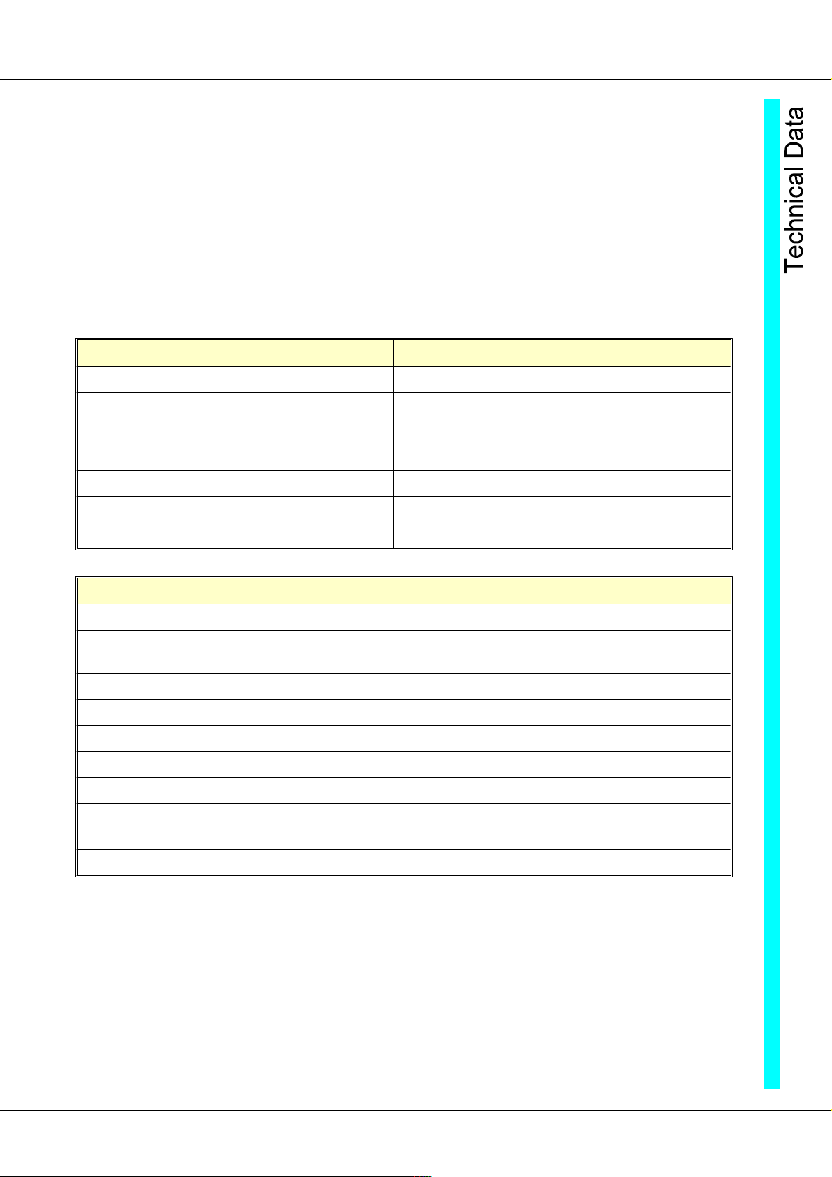
Technical data
TV6.2
Power connection only via an isolating transformer
No galvanic isolation between the power section and the control electronics.
Power connection TV6.2 30 to 120V~, 40 to 160V=
Output voltage TV6.2 24 to 120V= clock-pulse controlled
Cooling self
Device TV6.2 12
Output current continuous A= 12
peak A= 24
Max. el. power W 1440
Integrated quick fuses A 16
Armature choke type DR42 (0.5 mH)
Dimensions - plug-in device wxh 16TE 6HE
Dimensions - switch cabinet plug-in device wxhxd 170x240x80 mm
Common specification
Protection rating IP 00
ormat VDE 0100 group C
VDE 0160
Humidity rating class acc. to DIN 40040
Site of installation < 1000m above sea level
Operating temperature range 0 to 45°C
Extended operating temperature range up to 60°C reduced by 2%/°C
Storage temperature range -30°C to +80°C
Speed controller:
control precision without actual value error ± 0.1%
Control range 1: 1000
Table of contents


