Steiner SB648 Setup guide

MODEL :
75-71231 COMMERCIAL SNOWBLOWER-48’’ SB648
Manual 4172694
Rev. C 08-2015
4172694_en R-17082015
Printed in Canada

2

IMPORTANT MESSAGE
Thank you for purchasing this Schiller Grounds Care, Inc. product. You have purchased a world class product,
one of the best designed and built anywhere.
This product comes with an Owner / Operator’s Manual. The useful life and good service you receive from this
product depends to a large extent on how well you read and understand this manual. Threat this prod-
uct properly and adjust it as instructed, and it will give you many years of reliable service. This manual has been
provided to assist in the safe operation and servicing of your attachment.
See a Schiller Grounds Care, Inc. dealer for any service or parts needed. Schiller Grounds Care, Inc, service en-
sures that you continue to receive the best results possible from Schiller Grounds Care, Inc. products. You can
trust Schiller Grounds Care, Inc. replacement parts because they are manufactured with the same high
precision and quality as the original parts.
Schiller Grounds Care, Inc. designs and builds its equipment to serve many years in a safe and pro-
ductive manner. For longest life, use this product only as directed in the manual, keep it in good repair and follow
safety warnings and instructions. You’ll always be glad you did.
NOTE: All photographs and illustrations in the manual may not necessarily depict the actual models or attach-
ment, but are intended for reference only and are based on the latest product information available at
the time of publication.
Familiarize yourself fully with the safety recommendations and operating procedures before putting the machine
to use. Carefully read, understand and follow these recommendations and insist that they be followed by those
who will use this attachment.
This manual should be kept for future reference.
Please check if you have received all the parts for your kit with the list of the bag and the list of the box.
Schiller Grounds Care, Inc.
One Bob Cat Lane
Johnson Creek, WI 53038-0469
TABLE OF CONTENTS PAGE
DESCRIPTION / SPECIFICATIONS .................................................................................................................. 2
SAFETY ............................................................................................................................................................ 3
SAFETY DECALS ............................................................................................................................................. 6
ASSEMBLY INSTRUCTIONS ........................................................................................................................... 7
INSTALLATION .................................................................................................................................................. 9
ADJUSTMENTS & REMOVAL ........................................................................................................................ 10
OPERATION .................................................................................................................................................... 11
SERVICE ......................................................................................................................................................... 12
TROUBLESHOOTING .................................................................................................................................... 14
PARTS SECTION ............................................................................................................................................ 16
TORQUE SPECIFICATION TABLE ................................................................................................................. 26
OPTIONS ......................................................................................................................................................... 27

DESCRIPTION
This Snowblower is designed to facilitate clearing of large volumes of snow from sidewalks, driveways, and
small parking lots.
This is a 2-stage blower. The auger feeds the snow into the blower housing. The Snowblower is belt-driven with
a gearbox to the 16’’ open-centered auger. The hydraulic controlled chute directs the snow from side to side
with ngertip control of the auxiliary hydraulics. A heavy-duty wear edge shears snow cleanly from pavement or
height can be regulated with adjustable skid shoes.
The Snowblower mounts on select Steiner power units with quick hitch front lift and can be installed and
removed quickly.
SPECIFICATIONS
Weight: …………………………………………………………450 lbs
Overall Width: ………………………………………………...48’’
Overall Height: ………………………………………………..56’’
Overall Length: ……………………………………………….44’’
Opening Size: …………………………………………………27’’ h x 48’’ w
Auger: ………………………………………………………… 16’’ diameter open center
Blower: …………………………………………………………18’’ diameter 7’’ depth, 4 blades
Auger Speed: ………………………………………………….140 RPM
Blower Speed: ………………………………………………...700 RPM
Chute: …………………………………………………………..7’’ diameter, 243 degree rotation
Height of Cut: ………………………………………………….Adjustable skid shoes 0’’ to 3/4’’
NOTE: Specications are subject to change without notice.
SERIAL NUMBER : ___________________________
(IF APPLICABLE)
MODEL NUMBER: ___________________________
PURCHASE DATE : ___________________________
DESCRIPTION / SPECIFICATIONS
Record your attachment’s serial number and purchase date in the section reserved below. Your dealer requires this
information to give you prompt, efcient service when ordering replacement parts. Use only genuine parts
when replacements are required.
If warranty repairs are required please present this registration booklet and original sales invoice to your selling deal-
er for warranty service.
2

NOTICE !!!!
Unauthorized modications may present extreme
safety hazards to operators and bystanders and
could also result in product damage.
Schiller Grounds Care, Inc. strongly warns against,
rejects and disclaims any modications, add-on
accessories or product alterations that are not
designed, developed, tested and approved by
Schiller Grounds Care, Inc Engineering
Department. Any Schiller Grounds Care, Inc
product that is altered, modied or changed in any
manner not specically authorized after original
manufacture-including the addition of “after-mar-
ket” accessories by Schiller Grounds Care, Inc.-
will result in the Schiller Grounds Care, Inc.
Warranty being voided.
Any and all liability for personal injury and /or
property damage caused by any unauthorized
modications, add-on accessories or products not
approved by Schiller Grounds Care, Inc. will be
considered the responsibility of the individual(s) or
company designing and/or making such changes.
Schiller Grounds Care, Inc. will vigorously pursue
full indemnication and costs from any party
responsible for such unauthorized post-manu-
facture modications and/or accessories should
personal injury and/or property damage result.
This symbol means:
ATTENTION !
BECOME ALERT!
Your safety and the safety of others is in-
volved.
Signal word denitions:
The signal words below are used to identify levels of
hazard seriousness. These words appear in this
manual and on the safety labels attached to Schiller
Grounds Care, Inc. machines. For your safety and
the safety of others, read and follow the information
given with these signal words and/or the symbols
shown above. Regardless of the hazard be ex-
tremely careful.
DANGER Indicates an imminently hazardous sit-
uation which, if not avoided, WILL result in death or
serious injury.
WARNING Indicates a potentially
hazardous situation which, if not avoided, COULD
result in death or serious injury.
CAUTION Indicates a potentially
hazardous situation which, if not avoided, MAY result
in minor or moderate injury. It may also be used to
alert against unsafe practices or property damage.
CAUTION Used without the safety
alert symbol indicates a potentially hazardous situation
which, if not avoided, MAY result in property damage.
3
SAFETY

PREPARATION:
1. Thoroughly inspect the area where the accessory is
to be used and remoce door mats, all foreign objects
and the like.
2. Disengage all clutches and sift into nuetral before
starting engine.
3. Do not operate the accessory without wearing
adequate winter outer garments. Avoid loose tting
clothing that can get caught in moving parts. Wear
footwear that will improve footing on slippery surfaces.
4. Never attempt to make any adjustments while the en-
gine is running (except when specically recommented
by manufacturer).
5. Let the vehicle and accessory adjust to outdoor tem-
peratures before using.
6. Never use and accessory without proper guards,
plates, or other safety protective devices in place.
7. Always make sure to weat the appropriate safety
equipment required (glasses, muffs, mask...) for each
type of product. See operation section.
8. Always make sure of having safe traction on the vehi-
cle by using the recommended accessories.
SAFETY
Careful operation is your best insurance against an accident. Read this section carefully before operating the vehicle
and accessory. This accessory is capable of amputating hands and feet and throwing objects. Failure to observe the
following safety instructions could result in serious injury. All operators, no matter how experienced they may
be, should read this and other manuals related to the vehicle and accessory before operating. It is the owner’s
legal obligation to instruct all operators in safe operation of the accessory.
GLOSSARY:
In this manual, right and left sides are determined
by sitting on the seat of the vehicle facing forward.
In this manual, “accessories” means attachments
(snowblower, rotary broom, blade etc.) that you
install on the vehicle.
TRAINING:
1. Read this owner’s manual carefully. Be thoroughly
familiar with the controls and proper use of the
vehicle and accessory. Know how to stop the unit
and disengage the controls quickly.
2. Never allow children to operate the vehicle nor the
accessory. Never allow adults to operate the vehi-
cle nor the accessory without proper instructions.
3. No one should operate the vehicle nor the
accessory while intoxicated or while taking
medication that impairs the senses or reactions.
4. Keep the area of operation clear of all people,
particularly small children and pets.
4

OPERATION:
1. Do not put hands or feet near, under or inside
rotating parts.
2. Exercise extreme caution when operating on or
crossing gravel drives, walks or roads. Stay alert for
hidden hazards or trafc. Do not carry passengers.
3. After striking a foreign object, stop the engine
(motor), disconnect the wire from the spark plug(s)
and keep wire away to prevent accidental starting.
Thoroughly inspect the accessory for any damage
and repair damage before restarting and using the
accessory.
4. If the unit should start to vibrate abnormally, stop the
engine (motor) and check immediately for the cause.
Vibration is generally a warning of trouble.
5. Take all possible precautions when leaving the
vehicle unattended. Disengage the power take-off,
lower the attachment, place the transmission into
neutral, set the parking brake, stop the engine
and remove the contact key.
6. Never use the accessories across the face of
slopes, go from top to bottom. Exercise extreme cau-
tion when using equipment on slopes. Do not attempt
to clear a steep slope.
7. Never tolerate bystanders in the working zone.
Never use an accessory in the direction of by-
standers, it might throw gravel or debris that can
hurt people or damage property.
8. Never operate the accessory at high transport
speeds on slippery surfaces. Use care when
backing up.
9. Do not carry passengers.
10. Disengage power to the accessory when it is
transported or not in use.
11. Never operate the accessory without good visibil-
ity or light.
12. Do not overload the machine capacity by at-
tempting to clear snow at too fast a rate.
13. Use only attachments and accessories approved
by the manufacturer of the snow thrower/tractor
(such as wheel weight, counterweights, or cabs).
5
14. Never operate the snow thrower without proper
guards, and other safety protective devices in
place.
15. Stop the engine (motor) whenever you leave the op-
erating position, before unclogging the collector/im-
peller housing or discharge guide, and when making
any repairs, adjustments or inspections.
SAFETY
MAINTENANCE AND STORAGE
1. When cleaning, repairing or inspecting the vehicle
and accessory, make certain that all moving parts
have stopped. Disconnect wire from the spark
plug(s) and keep wire away to prevent accidental
starting.
2. Check all the bolts and components at frequent
intervals to make sure that they are properly
tightened.
3. Always refer to the owner’s manual when you store
the accessory and vehicle for a prolonged or an
unspecied length of time.
4. Maintain or replace safety and instruction labels, as
necessary.
5 Let the engine run for a few minutes after cleaning
snow in order to prevent the rotary parts from
freezing.

SEE PARTS BREAKDOWN FOR DECAL LOCATION
DECAL #105126
To avoid serious injury:
Keep hands, feet & clothing away from
rotating auger while engine is running.
DECAL #105127
To avoid serious injury:
Keep hands out of this discharge chute while
engine is running.
DECAL #105128
To avoid injury from drive belt:
Keep hands, feet & clothing away.
Do not attempt to install or remove drive belt
without reading owner’s manual.
DECAL #105130
Before installing or using:
Locate, read and make sure to understand
all of the owner’s manual.
DECAL #105131
Refer to owner’s manual about wearing
safety glasses, ear muffs and mask. Re-
fer to owner’s manual for use of counter
weights, cat tracks and tire chains.
DECAL #106378
To avoid serious injury:
Keep hand & clothing away from rotating
gear while the hydraulic motor is connect-
ed. Always use the snowblower with all the
guards in place.
6
REPLACE IF DECALS ARE DAMAGED
SAFETY
DECALS

Tools Required
Wrench: 9/16” , 7/16”, 1/2”
Ratchet
Socket: 916”, 7/16”
Pliers
Allen Key
Axle Stands
Refer to parts breakdown section for parts identication.
STEP 1
Snowblower Preparation:
1. Remove the snowblower from te shipping crate.
2. Remove the support plates from skid shoes.
7
ASSEMBLY INSTRUCTIONS
Chute Installation:
NOTE: This step requires two people.
1. Wrap the rotation ring (item 1) (groove inside)
around the edge of the discharge chute (item 2) as
shown.
2. Place the chute (item 3) (opening facing forward)
over the rotation ring.
IMPORTANT: The ring must be inside the base
of the chute. It is the chute that will hold the
rotation ring in place.
3. On the right side of snowblower, install the
grooved rotation ring (item 4) under the chute as
shown.
4. Secure the chute and rotation ring in place with six
hex bolts 1/4’’ x 1 1/4’’ (item 5) and nuts as shown.
Do not tighten too rmly.
5. On the left side of the snowblower, install the other
half of rotation ring (item 6) under the chute as
shown.
6. Secure the chute and rotation ring in place with
three hex bolts 1/4’’ x 1 1/4’’ (item 7) and nuts (as
shown). Do not tighten the nuts too rmly.
(Nuts that are too tight might prevent the chute from ro-
tating side to side. Only a slight pressure is necessary).

Sprocket guard installation:
1. Adjust the hydraulic motor (item 1) by loosening
the three nuts on the carriage bolts (item 2)
that hold the hydraulic motor in place. Do not
remove the nuts.
2. Slide the motor towards the chute (item 3) as
shown (the grooves on the motor’s sprocket
must match those of the rotation ring). Adjust and
retighten the nuts. Tighten rmly.
3. Install the sprocket guard (item 4) as shown
and secure in place with two 1/4’’ x 1/2’’ bolts
(item 5).
WARNING
Operate only when all the guards are in place.
8
ASSEMBLY INSTRUCTIONS

STEP 2
SNOWBLOWER INSTALLATION:
1. Attach snowblower to the power unit.
2. Be sure drive belt is in place over the left hitch arm.
3. Drive the power unit into the hitch arms and latch the quick hitch handle.
4. Stop the engine.
TO PREVENT INJURIES: STOP THE MOTOR. APPLY PARKING BRAKE. REMOVE THE
IGNITION KEY. DISCONNECT THE WIRE FROM THE SPARK PLUG(S) AND KEEP
AWAY FROM SPARK PLUG(S) TO PREVENT ACCIDENTAL STARTING.
5. Install the drive belt and adjust drive pulley position.
6. Attach the two hydraulic hoses to the quick couplers on the tractor.
NOTE: If the rotation does not match the lever operation, the hoses may be reversed.
7. Install the drive belt to the tractor. (See tractor’s manual for belt tensioning specications).
8. A weight bar with six weights is required on 4-wheel drive units whenever the snowblower is installed. Install
according to weight bar instructions
9. For models without an electric clutch, go to a safe location, place a security barrier all around the snow-
blower. Raise the snowblower to it’s highest point and then lower to it’s lowest point. If the snowblower
starts without engaging the P.T.O., lower the drive belt tension according to the tractor’s owner’s manual.
TO PREVENT INJURIES:
THE PERSON WHO INSTALLS THE DRIVE MECHANISM HAS THE RESPONSIBILITY TO
MAKE SURE THAT WHEN THE CLUTCH IS DISENGAGED THAT ALL MOVING PARTS
STOP. FOR MORE INFORMATION, DO NOT HESITATE TO CONTACT THE TECHNICAL
SUPPORT.
NEVER USE THE SNOWBLOWER WITHOUT THE BELT GUARD.
10. Raise the parking stand:
Remove the pin (item 1, raise the parking stand (item 2) and
reinstall the pin.
IMPORTANT: (to avoid damages)
You must RAISE the parking stand AFTER installing the accesso-
ry on the tractor.
Take care to avoid being pinched by the
parking stand.
9
INSTALLATION
IF THE SNOWBLOWER STARTS WITHOUT ENGAGING THE P.T.O. STOP THE ENGINE.
IMPROPER TENSION.

STEP 3
ADJUSTMENTS
Drive pulley adjustment:
NOTE: Place the tractor horizontally on a at surface.
1. The tractor pulley (item 60) and the snowblow-
er pulley (item 61) must be well aligned (dis-
tance B must be close to 0’’ as possible) Make
sure there is no contact between the two belts
when the snowblower is in the highest position.
2. For tractor without electric clutch : do the
same tests as in snowblower installation
section, step 9. If the snowblower starts and
proper tension is used, the pulleys are mis-
aligned too much.
If at the highest position the two belts come
into contact with each other, there is not enough
space between the pulleys.
3. On 440 tractors, to prevent snowblower from
contacting front of tractor during full lifts, po-
sition the lift cylinder and pin into the bottom/rear
hole on the lift arm as shown on picture:
NOTE: Failure to position the lift cylinder as shown
can result in damage to the tractor and or the snow-
blower.
Skid shoe adjustment:
LEVEL PAVED SURFACE: Adjust skid shoes to allow 3/16” to 1/4” clearance between cutting edge and
surface.
UNEVEN OR GRAVEL SURFACE: Adjust skid shoes to allow 1/2” to 3/4” clearance between cutting edge and
surface.
When you have conrmed the alignment, put thread
locking on set screw and torque at 183 lbs-in.
STEP 4
SNOWBLOWER REMOVAL INSTRUCTIONS:
1. Lower parking stand.
2. Lower the snowblower and stop engine
TO PREVENT INJURIES: STOP THE MOTOR. APPLY PARKING BRAKE. REMOVE THE IGNITION KEY.
DISCONNECT THE WIRE FROM THE SPARK PLUG(S) AND KEEP AWAY FROM SPARK PLUG(S) TO
PREVENT ACCIDENTAL STARTING.
3 .Disconnect the two hydraulic hoses and install dust covers.
4. Remove the drive belt and release the quick hitch. Start the engine and back out carefully.
5. Remove the weights from the weight bar for the 4 wheel drive unit.
10
ADJUSTMENTS & REMOVAL

OPERATION
STEP 5
OPERATING INSTRUCTIONS:
1. Make sure the snowblower is clear of snow before engaging the snowblower.
2. Make sure that the auger and impeller operate freely.
3. Start the tractor engine.
IMPORTANT: USE FULL ENGINE R.P.M. WHEN REMOVING WET OR STICKY SNOW.
LOW R.P.M. WILL TEND TO PLUG THE CHUTE.
4. Engage P.T.O. slowly and maintain engine speed at 3/4 to full throttle.
5. Low range works best for most conditions. Adjust speeds to match snow conditions. The snowblower
works best with plenty of snow being fed into the blades. In light snow (4’’ to 6’’ or 10 to 15 cm) increase
travel speed.
6. Float position may be used, but carrying some of the weight with the power unit gives better traction. May
require frequent lifting and lowering on 4-wheel drive units. If drive belts slips, adjust drive belt tension
according to power unit manual. Never put down force on the snowblower.
7. Rotate chute using the auxiliary hydraulic control lever. Try to blow snow with the wind on windy days.
8. Set the angle of the deector according to the distance the snow must be thrown and to prevent property
damage. To change the deector angle, loosen the two deector knobs & adjust the deector to
the appropriate angle and retighten the two knobs securely. If equipped with an Electric Deector Kit, use
the toggle switch for up or down deector movement.
9. When removing snow, do not use the snowblower as a dozer blade to push snow. Allow snowblower
to ingest snow at its own speed. If the speed of your tractor is too fast, the snowblower may
become overloaded and plug. For best results, raise the snowblower and remove a top layer of snow. A
second pass with the snowblower will remove the remaining snow.
CLEARING A CLOGGED DISCHARGE CHUTE:
Hand contact with the rotating impeller inside the discharge chute is the most common cause of inju-
ry associated with snowblowers. Never use your hand to clean out the discharge chute.
To clear the chute:
1. Lower snowblower to the ground and set parking brake.
2. SHUT THE ENGINE OFF & REMOVE KEY!
3. Wait 10 seconds to be sure that all moving parts such as the impeller blades have stopped moving.
4. Disconnect wire from the spark plug(s) and keep wire away to prevent accidental starting. Always use a
clean-out tool (chute shovel) supplied with this snowblower. NEVER USE YOUR HANDS!
ASSURE CLEAR DISTANCE IN THE DIRECTION OF THROWING SNOW. OBJECTS
CAN BE PROPELLED FROM BLOWER CAUSING POSSIBLE DAMAGE TO PROPER-
TY OR INJURY TO PERSON.
BE ALERT! WATCH FOR BURIED OBJECTS IN THE SNOW WHICH COULD BE
THROWN OR CAUSE DAMAGE TO MACHINE.
NEVER TRAVEL AT SPEEDS THAT WOULD CAUSE DAMAGE TO THE MACHINE OR
INJURY TO THE OPERATOR IF THE MACHINE WERE TO BE STOPPED SUDDENLY BY
AN IMMOVABLE OBJECT.
READ THE TRACTOR OWNER’S MANUAL CAREFULLY. BE THOROUGHLY FAMILIAR
WITH THE CONTROLS & PROPER USE OF THE ATTACHMENT. KNOW HOW TO STOP
THE ATTACHMENT & DISENGAGE THE CONTROLS QUICKLY.
11
SERVICE SCHEDULE
TO PREVENT INJURIES: STOP THE MOTOR. APPLY PARKING BRAKE. REMOVE THE IGNITION KEY.
DISCONNECT THE WIRE FROM THE SPARK PLUG(S) AND KEEP AWAY FROM SPARK PLUG(S) TO
PREVENT ACCIDENTAL STARTING.
Daily:
- Check for any damage on the hydraulic hose. The hydraulic hose must be replaced if there is any
small damage.
- Check for any signs of loose bolts and tighten as needed. Check mounting bolts at frequent inter-
vals for proper tightness in order to prevent costly repairs. Make sure your snowblower is in
safe working condition.
- Check skid shoe (see installation section).
- Check from to time the wearing on the cutting edge to make sure you do not wear out the base of the
snowblower’s chassis. This cutting edge is reversible. All you have to do is unscrew the bolts and
turn the cutting edge, reinstall and tighten the bolts securely.
50 Hours:
- Check drive belts for proper tension and signs of cracking.
100 hours:
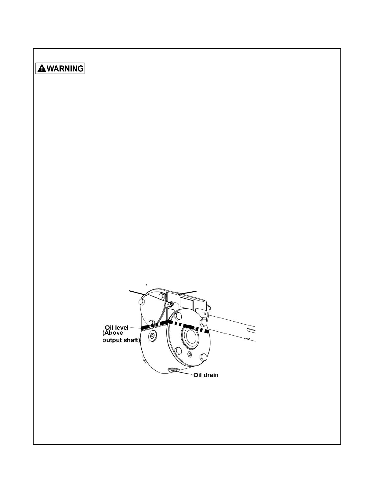
- Change the oil in the gear box after the rst 100 hours of use. Then change after every 2500 hours or
every 6 months. The type of oil used: S.A.E. grade 80W90.
- The gear box should have a total of 500 ml of oil or lled above the output shaft (see gure).
Grease
tting
12
Oil tting
SERVICE

AUGERS AND FAN SHEAR BOLT REPLACEMENT
Shear bolts are to be considered a preventive measure and not an assured protection. Operator vig-
ilance is required. Thoroughly inspect the areas where the snowblower is to be used and remove
all foreign objects.
To avoid damage to the snowblower:
Use only the original shear bolts (grooved bolts).
#4172551-13 bags of 10 for the augers.
#4172551-14 in bags of 10 for the fan.
The use of any other shear bolt will not insure any protection and may void the warranty.
IMPORTANT: IT IS VERY IMPORTANT TO REPLACE THE AUGERS IN THE SAME POSITION AS SHOWN
IN THE DRAWING BEFORE INSTALLING THE SHEAR BOLTS. ONE SIDE AUGER SHOULD BE OPPO-
SITE OF THE OTHER SIDE.
UP
DOWN
END OF SEASON STORAGE
- Clean snowblower and subframe thoroughly and repaint all parts from which paint has worn.
- List the replacement parts that will be needed for the next season.
- Store the snowblower and the subframe in a dry place.
- Follow the instructions in the Lubrication section.
13
SERVICE

TROUBLESHOOTING
* Please refer to parts breakdown section for parts identication.
14
TROUBLESHOOTING
PROBLEM POSSIBLE CAUSES CORRECTIVE ACTION
One section or both sections of the
auger stops turning. Shear bolts are probably broken. Replace shear bolt (for identication,
see parts list “Snowblower”).
Fan stops turning. Shear bolt is probably broken. Replace shear bolt (for identication,
see parts list “Snowblower”).
Snowblower stops turning. One of the two belts is probably
damaged or broken. Check both belts and replace
damaged belt(s) (for instructions, see
Maintenance section, Installation,
Adjustment and Replacement
section).
Snowblower belt has burn marks in
specic places or the belt slips.
Lack of tension on belt.
Snowblower engaged when
plugged.
Remove the hair pin (item 1) then
screw the bolt under the hair pin until
good tension on the belts. Then
reinstall the hair pin to lock the bolt
rotation.
1
Make sure the auger & the fan are not
frozen or plugged before engaging.
Chute plugs easily. Tractor engine turning too slowly.
Advancing too quickly with tractor.
Run engine at full throttle during
snowblowing operation.
Allow snowblower to ingest snow at its
own speed.
Chute rotation is difcult. Dirt or ice may be underneath
chute. Dismount chute (see installation
section). Clean the base of chute and
the rotation ring. Lubricate & re-install.

15
TROUBLESHOOTING
PROBLEM POSSIBLE CAUSES CORRECTIVE ACTION
Snowblower digs into ground. Ground is not frozen or too soft. Adjust skid shoes lower so they
may better support the snowblower.
Snowblower vibrates or is
abnormally noisy. Damaged pulley.
Damaged bearing.
Damaged fan.
Damaged auger.
Replace pulley.
Replace bearing.
Dismount & repair or replace fan.
Replace auger.
Drive belt has burn marks in specic
places or belt slips. Lack of tension on the belt. See tractor’s manual for tensioning
instructions.

PARTS SECTION
PARTS SECTION
16

17 O/L = Obtain Locally

18
This manual suits for next models
1
Table of contents
Other Steiner Snow Blower manuals


Popular Snow Blower manuals by other brands


Craftsman
Craftsman 247.886700 owner's manual

Blizzard
Blizzard 760TR Installation instructions & owner's manual

Simplicity
Simplicity 476 owner's manual

SNOWJOE
SNOWJOE 24V-X2-SB18U-CT Operator's manual

Ventrac
Ventrac LX420 Owner/operator's manual & parts list

Briggs & Stratton
Briggs & Stratton Canadiana CH 61900 Safety, operation and maintenance manual