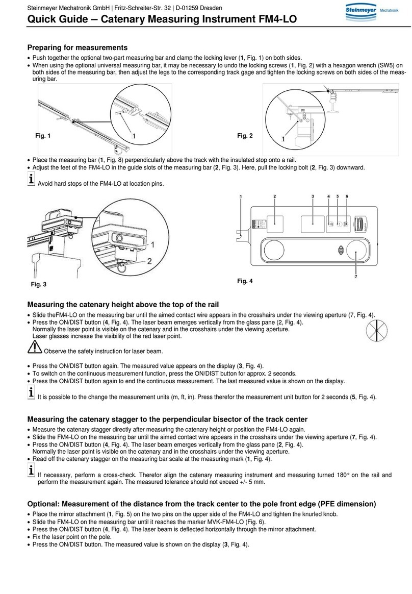
Steinmeyer FM5-BT User manual

Steinmeyer Mechatronik GmbH | Fritz-Schreiter-Strasse 32 | D-01259 Dresden
Quick Guide – Catenary Measuring Instrument FM5-BT
Preparing for measurements
•Connect the optional two-part measuring bar and mount clamping lever (1, Fig. 1) on both sides.
•When using the optional universal measuring bar, it may be necessary to undo the locking screws(1, Fig. 2) with a hexagon wrench (SW5) on
bothsides of themeasuring bar, then adjust the legs to the corresponding track gage and tighten the locking screws on both sides of the measur-
ing bar.
•Place the measuring bar (2, Fig. 8) perpendicularly above the track with the insulated stop onto a rail.
•Adjust the feet of the FM5-BT in the guide slots of the
measuring bar (2, Fig. 3). Here, pull the locking bolt (3, Fig. 3) downward.
•Press the brake on the FM5-BT (1, Fig. 3)and slide themeasuring instrument
over themeasuring bar.
Keep pressing the brake while sliding the FM5-BT over the measuring bar.
For design-related reasons an offset value of (-0.0233 m) is set on the measuring instrument.
The activated offset function is indicated with a symbol on the display (4, Fig. 4):
Do not change this factory setting.
Measuring the catenary height above the top of the rail
•Set the triangular grip (3, Fig. 4) on the FM5-BT to HEIGHT. Switch on the FM5-BT via the ON/DIST button (2, Fig. 5).
The laser beam emerges vertically from the FM5-BT.
•To switch onthe screen display,press the
CAM button (10,Fig.5)once and press the up arrow button (3, Fig. 5) once.
Slide the FM5-BT with the brake pressed along the measuring bar until the target catenary appears in the crosshairs on the display.
•To achieve the best possible measuring results, select the zoom factor to 2x or 4x with the Up/Down arrow buttons (3 / 7, Fig. 5).
The laser dot is normally visible on the catenary and on the display. The use of laser glasses makes it easier to see the laser dot.
•Press the ON/DIST button again. The measured value appears on the display.
•To switch on the continuous measurement function, press the ON/DIST button for approx. 2 seconds.
•Press the ON/DIST button again to end the continuous measurement; the last measured value is then shown on the display.
Measuring the catenary stagger to the perpendicular bisector of the track center
•The targeted catenary appears in the crosshairs on the display, and/or the red laser dot is visible on the catenary.
•Read off the catenary stagger on the measuring bar scale at the
measuring mark (1,Fig. 4).
For Bluetooth®data transfer:
•Press and hold the brake and then slide the laser beam reflector (1, Fig. 8) along the measuring bar up to the red stop on the measuring bar slot.
•Set the triangular grip (3, Fig. 4) on the FM5-BT to SIDE. The laser beam emerges horizontally from the FM5-BT.
Now measure the distance to the laser beam reflector.
•The measured value sent via Bluetooth®can be converted e.g. in Excel format to the correct measured value for the catenary stagger by sub-
tracting an offset value. The negative offset value is set to 1000 mm for the standard measuring bar and corresponds to the measured value
from the zero mark on the measuring bar scale (FM5-BT in track center position) up to the laser beam reflector.
Measurement of the distance from the track center to the pole front edge (PFE dimension)
•Set the triangular grip (3, Fig. 4) on the FM5-BTto SIDE. The laser beam emerges horizontally from the FM5-BT.
•To ensure that the laser beam reaches the side pole unobstructed, remove the laser beam reflector (1, Fig. 8) from the measuring bar if re-
quired.
The laser beam reflector can be slid into the guide slots of the wide measuring bar foot and stored there.
•Slide the FM5-BT along the measuring bar with the brake pressed until it reaches the PFE marker (PFE-FM5) (Fig. 7).
•Press the ON/DIST button and fix the laser point on the pole; if necessary, use the screen view (CAM button) and the camera zoom.
•Press the ON/DIST button and the measured value will then appear on the display.
Tilt measurement
•The tilt is displayed continuously by default in either degrees or mm/m on the top right of the display (Fig. 6).
The tilt angle and track gage can be used to calculate the track superelevation.
Fig. 1
Fig. 2
Fig. 3
Fig. 4

Steinmeyer Mechatronik GmbH | Fritz-Schreiter-Strasse 32 | D-01259 Dresden
Quick Guide – Catenary Measuring Instrument FM5-BT
Bluetooth®data transfer
•Press the FUNC button (4, Fig. 5) and navigate through the menu settings (shown on the display: ) to Bluetooth®.
•Press "=" (11, Fig. 5) to confirm Bluetooth®and then press the C/OFF button (8, Fig. 5) to exit the settings.
•Establish a Bluetooth®connection to your laptop, tablet or smartphone. A blue Bluetooth®icon will appear at the top left of the display (Fig. 6).
The following options are available for transmitting measuring results via Bluetooth®:
-
using the application software FMcapture©, version 4.0©or higher (for Microsoft Windows 8.1 and 10)
-
using the app mode (after downloading available software for the operating systems Microsoft Windows, Android or iOS)
-
in keyboard mode (without separate software)
Steinmeyer Mechatronik accepts no liability for free software and therefore also offers no support for such programs.
Power supply / USB charging
•Recharge the lithium-ion battery after the FM5-BT has been in storage for a long period of time or, at the latest, when the battery icon at the top
left of the display starts to flash (Fig. 6).
•Unscrew and remove the protective cap (7, Fig. 4) on the FM5-BT and slide the protective lid that is behind it to the right.
•Connect the FM5-BT to a mains outlet using a USB cable and a power supply unit with the right adapter for your country.
A charging icon is shown on the display during the charging process. End the charging process once the battery is fully charged or after around
4 hours.
The FM5-BT cannot be used while it is charging.
It is also possible to recharge the battery via a USB cable that is connected to a computer, but this will take longer.
You can also recharge the unit via a USB cable and a car USB recharging adapter (12 V) that is plugged into a power socket in a car.
Notes
Laser radiation: The FM5-BT is a class 2 laser device. Do not look directly into the laser beam (warning sign on the FM5-BT).
Hints for use: Keep the FM5-BT clean and dry. It is particularly important to keep the glass plates clean. Avoid dropping the unit and other
forms of mechanical damage. Acclimatise the FM5-BT unit before using it, and avoid large jumps in temperature.
Operator responsibility: The operator is responsible for making sure that the unit is used properly and for the operational safety and reliability of the
equipment, as well as for compliance with applicable safety requirements, accident prevention regulations, environmental reg-
ulations and occupational health and safety regulations.
Control measurements: Regular control and reference measurements to determine the measurement tolerances should be performed. To determine
the tolerance for the catenary stagger, align the FM5-BT with measuring bar rotated through 180° on the track and perform the
measurement again.
Repairs: All repairs and inspection work are performed by technical personnel at the manufacturer.
Inspection interval: The inspection interval is 2 years. Observe the test report and the test sticker on the FM5-BT.
Further information: Refer to the additional information provided in the operating instructions of the FM5-BT. Further documents are available on
request.
Fig. 7
Fig. 5
Fig. 6
Fig. 8
Table of contents
Other Steinmeyer Measuring Instrument manuals
Popular Measuring Instrument manuals by other brands
Hanna Instruments
Hanna Instruments HI99151 Quick reference guide

Textron
Textron HD Electric Proof Tester PT-5000 Operating instructions manual
Bushnell
Bushnell Yardage Pro 20-0750 user guide
Siemens
Siemens Sitrans F Series quick start

CORNING
CORNING 315 installation manual
Endress+Hauser
Endress+Hauser Proline Prosonic Flow 93 Function manual
