Stella iR4-LGDW User manual
WWW.STELLADORADUS.COMWWW.STELLADORADUS.COM iREPEATER
iREPEATER
11
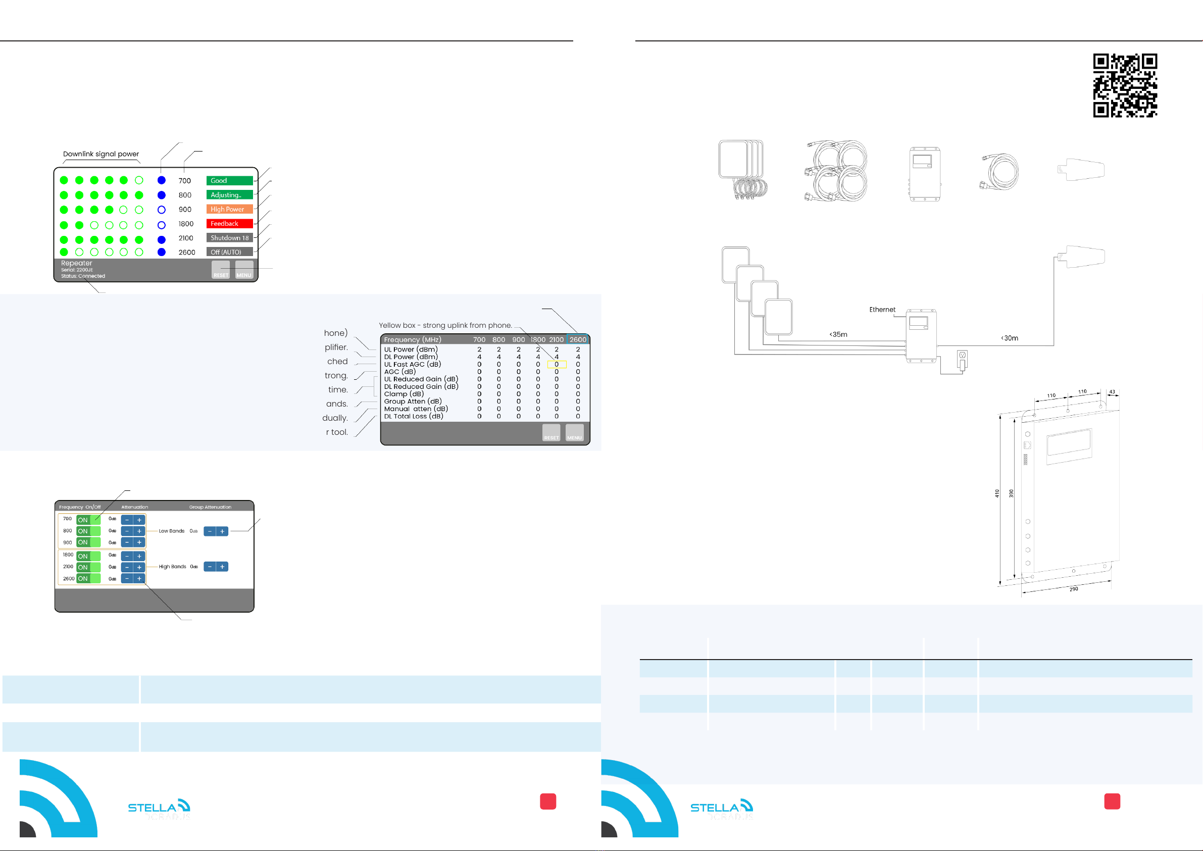
Contents of the kit
Dimensional Drawing(mm)
Snap QR code to visit
Installer Zone for more
installer resources.
This manual is for the following models
Blue box - band is active
The LCD allows users to easily read the repeater diagnostics, control the gain of each band, turn on/off any band, and
easily allows for general conguration.
*The iR4 has only 2 ports for 2 internal antennas.
dB Page
Main Page
LCD - 5” full colour touch Quick installation and user manual
Long press to reboot:This is similiar to plugging out and in mains power.
Short press to reset: This just rebalances the levels.
Band is Active.
Frequency
No issues
Band is self optimizing.
Strong outdoor signal. No action required as the repeater will self optimize.
Indoor and outdoor antennas are too close to each other. Separate them more.
External signal is too strong and band has shut down. Add manual attenuation.
Band has automaticlly turned off due to very high downlink (DL) power.
Internet status
2-After using group attenuators, use these individaul attenuators to do ne adjustments per band.
Uplink (UL) power received by the amplier. (Power emitted by the phone)
DL power from the operator, received by the amplier.
UL Automatic Gain Control (AGC) - starts when UL power limit is reached
AGC for UL and DL when the operator’s signal is strong.
When outdoor signal is very strong, gain is reduced for an extended time.
Add extra attenuation to high or low bands.
Add attenuation to any band individually.
Sum of total AGC on the DL. This value can be used in FloorPlanner tool.
Yellow box - strong uplink from phone.
Outdooor
antenna
*Outdoor 15m
cable SD400
*Indoor
antennas x 4
Indoor cables
4x SD400
*Custom cable lengths supplied
iRepeater
PIN Access A secret PIN can lock out access to the LCD display. The PIN is set on the clients account on the platform. Default
PIN 888888,
Internal location Enter a note about the amplier. This note is sent and displayed on the stellacontrol inventory page. E.g. Internal
location of the amplier.
Other LCD features
Toggle Band Page
Model Bands Ports PSU Weight Dims cm
iR4-LGDW* B20,B8,B3,B1 2 12V,5A 1.6kg 27X29X3.8
iR5-EU B 2 0 , B 8 , B 3 , B 1 , B 7 4 12V,5A 2.8kg 43X30X3.8
iR6-EU B28, B20, B8, B3, B1, B7 4 12V,5A 2.8kg 43X30X4.8
iR5-US B28, B4, B5, B25, B7 4 12V,5A 2.8kg 43X30X4.8
1-Use high and low group attenuator to control either the low bands 700/800/900
and/or the high bands, 1800/2100/2600.
Use these group attenuators to rst control very strong signal. Then, make ne
adjustments with the individual attenuators.
Switch On/Off band

WWW.STELLADORADUS.COMWWW.STELLADORADUS.COM iREPEATER
iREPEATER
22
2- Outdoor antenna placement.
1-Survey
Step-by-step installation instructions
3- Loose installation
4- Call and data tests
5- StellaControl - Remote monitoring
On the roof, point the outdoor antenna towards the nearest cell tower. This nearest, most
suitable cell tower can be either seen by eye or located using on-line tower maps.
When the best direction is found, loosely fasten the antenna to a pole.
The Yagi should be clear of all nearby obstructions, like metal railings or other roof
structure.
Before starting the installation, conduct call and data speed tests outside the building to understand the available
signal in your area. For the required mobile operators note:
• Call quality. (do you experience dropped voice calls?)
• Data speeds up and down.
• Signal strength (signal bars or dBm)
• Band (only available on android phones)
• Service: H+/4G/5G
Whatever signal is available outside your property, a repeater will distribute inside the property.
For android phones, the app, Network Cell Info Lite is recommended.
Loosely drop the 15m SD400 cable from the outdoor antenna to a location inside the building where call tests can be conducted.
Attach this cable to the repeater and power on the repeater. On the LCD, pay attention to the signal bars for each frequency. 4,5 or
6 signal bars signies a good signal at that frequency.
Next, attach one of the inside antennas to the repeater and point it into the room.
Do call and data tests for each mobile operator. The tests should be comparable to those tests conducted outside the property.
Once satised with the results, fasten the outdoor antenna and install the cables permanently.
Connect the iRepeater to a live ethernet conection. Log onto your stellacontrol account.
Manage, monitor and control all your iRepeaters from the cloud.
To learn more snap the QR code.
Add lineamps for more coverage.
For larger buildings, lineamps and splitters can be installed after the repeater. This allows extending the signal a
further 100m into the building. See cable length rules below.
Cable Assembly
Self assembly of cables. Pay careful attention to the N-connectors.
The silver braid must be long.
Braiding must not touch
centre pin. Check Carefully.
Braid must overlap with the
collar of the connector. This
is what holds the connector
in place.
Centre pin must be level with the
steel collar. Not pushed inside.
This manual suits for next models
3


