Steridose STERIFLANGE User manual
1
STERIDOSESALES
HeadOffice
Himmelsbodavägen 7·P.O.Box120 ·SE-147 22 TUMBA ·SWEDEN
Phone:+46-844999 00 ·Fax: +46-8449 99 90
info@steridose.com · www.steridose.com
RegionalOffice
5020 WorldDairyDrive ·Madison,WI53718 ·USA
Phone:+1-608 229 5225 ·Fax:+1-608 227 9599
info@steridose.com · www.steridose.com
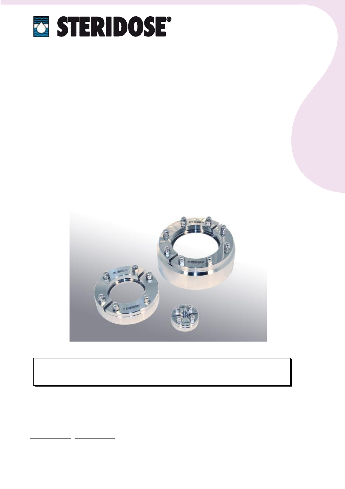
STERIFLANGE®
Welding Guide
Welding the flange intoposition
Thisweldingguideshould beread carefully
beforeunpackingtheSteriflange®
OrderNo.____________

2
STERIDOSESALES
HeadOffice
Himmelsbodavägen 7·P.O.Box120 ·SE-147 22 TUMBA ·SWEDEN
Phone:+46-844999 00 ·Fax: +46-8449 99 90
info@steridose.com · www.steridose.com
RegionalOffice
5020 WorldDairyDrive ·Madison,WI53718 ·USA
Phone:+1-608 229 5225 ·Fax:+1-608 227 9599
info@steridose.com · www.steridose.com
Table ofContents
1. ABOUTTHEWELDING GUIDE.............................................................................3
2. GENERAL...................................................................................................................4
3. POSITIONING AND ORIENTATIONOFSTERIFLANGE……………….........4
3.1 ORIENTATION OFSTERIFLANGE....................................................................................4
3.2 DISTANCE BETWEEN WELDS.............................................................................................5
3.3 DISTANCE FROMOUTER EDGE........................................................................................5
4. OPTIMUMALIGNMENTOFSTERIFLANGE®.....................................................6
5. MAKINGAND PREPARATIONOFHOLEINTHEGABLE...............................6
6. WELDING (TIG), TACK WELDING THESTERIFLANGE..................................7
7. FINAL WELDING......................................................................................................9
8. AFTER WELDING.....................................................................................................10

3
STERIDOSESALES
HeadOffice
Himmelsbodavägen 7·P.O.Box120 ·SE-147 22 TUMBA ·SWEDEN
Phone:+46-844999 00 ·Fax: +46-8449 99 90
info@steridose.com · www.steridose.com
RegionalOffice
5020 WorldDairyDrive ·Madison,WI53718 ·USA
Phone:+1-608 229 5225 ·Fax:+1-608 227 9599
info@steridose.com · www.steridose.com
1. AbouttheWeldingGuide
Theweldingproceduredescribedin thisguideisusedforweldingflange in tovessels.The
guidelinesreferonlytothetechnicalaspectsofweldingoperations.Pleasenotethatalldatawith
regardtoweldingcurrent,timeetcareapproximateand mayvaryin practice.Referencesaremade
totheSwedishcodeforpressurevessels,TKN87. Ensurethattherelevantstandardsforpressure
vesselsarecomplied withthevessel.
RoplanABs liabilityforpossiblefaultsareregulatedbyECE 188. ThisimpliesthatRoplanABis
responsibleforfaultspresentin theproductatthetimeofdelivery.
RoplanABisnotresponsibleforfaultsthatoccurduetoconditionsthatariseafterdelivery,for
examplefaultyhandling,weldingorfitting.
Asastepin RoplanABs qualityassurance,eachflange isinspectedpriortodeliverytoensure
conformance withregardtosize and otherrequirementsoftheRoplanABs drawings.Acertificate
isenclosed with each delivery.
Thisprocedureensuresthattheprobabilityofan original faultisverysmall. Faultsthatdooccurcan
normallybetraced to incorrecthandling, weldingorfitting.
RoplanABs experience isthatthegreatestriskofafaultoccurringisdeformation in connection
with weldingtheflange into thegableend ofthevessel.
Tominimisetheriskoffaultsoccurringafterdeliveryfrom RoplanABitisessentialthatthis
weldingguideisstudiedand thatonlyproperlytrainedand experiencedpersonnelareemployedin
theweldingoperations.
Forothercountriesthan Sweden, pleasemakesurethattherelevantstandardsforthatcountryare
complied with.
Thepurposeofthismanual isto avoid deformation oftheSteriflange dueto releaseoftension
forcesin thegable.
Thismanual should onlyberegarded asan aid in theweldingwork and notoverridethelegal
obligations.
4
STERIDOSESALES
HeadOffice
Himmelsbodavägen 7·P.O.Box120 ·SE-147 22 TUMBA ·SWEDEN
Phone:+46-844999 00 ·Fax: +46-8449 99 90
info@steridose.com · www.steridose.com
RegionalOffice
5020 WorldDairyDrive ·Madison,WI53718 ·USA
Phone:+1-608 229 5225 ·Fax:+1-608 227 9599
info@steridose.com · www.steridose.com
2. General
TheSteriflange maybeweldedintothevesselbeforeit’sweldedtogether.Itcanalsobeweldedin
an alreadyfinished vessel.
Itisvitalthatall otherweldingonthelowergableend iscompletedbeforemakingaholeforthe
flange.Examplesofsuchweldingthatmayberequiredarebottom outletvalves,connection
adaptersforsensorsand sampleportsetc.
3. Positioningand Orientation ofSteriflange
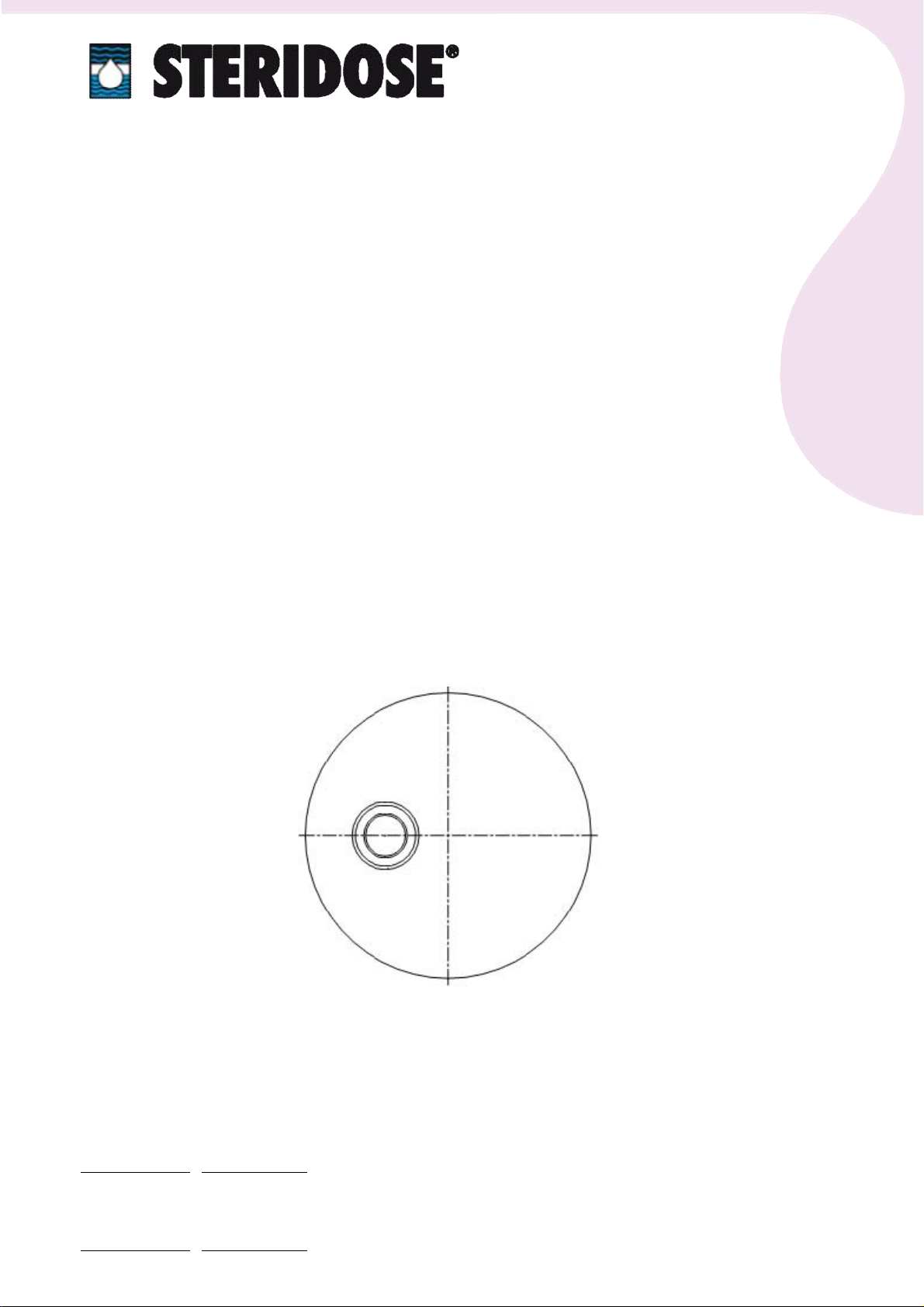
3.1 Orientationof Steriflange
In orderto connectpipe, etc. into theSteriflange, ensurethatno otherequipmentwill bein conflict
with theassembled parts. Also makesurethatthere'senough space to mount/dismountthelocking
ring.
5
STERIDOSESALES
HeadOffice
Himmelsbodavägen 7·P.O.Box120 ·SE-147 22 TUMBA ·SWEDEN
Phone:+46-844999 00 ·Fax: +46-8449 99 90
info@steridose.com · www.steridose.com
RegionalOffice
5020 WorldDairyDrive ·Madison,WI53718 ·USA
Phone:+1-608 229 5225 ·Fax:+1-608 227 9599
info@steridose.com · www.steridose.com
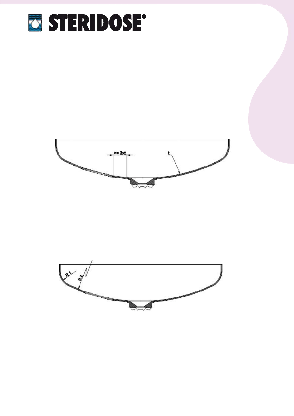
3.2 DistancebetweenWelds
Thesmallestpermissibledistance betweentheweldseamofaflangeandanyotherweld isthree
timesthethicknessofthematerialofthegableend, 3xt,accordingtothe1987 Swedishstandards
forpressurevessels,TKN87.
3.3 DistancefromOuter Edge
Theflange mustbepositionedin suchaway thatnopart ofitsweld liesoutsidethelarge radiusR2,
see figure. Weldinginsidethesmall radiusR1 isnotpermitted, accordingto TKN 1987.

6
STERIDOSESALES
HeadOffice
Himmelsbodavägen 7·P.O.Box120 ·SE-147 22 TUMBA ·SWEDEN
Phone:+46-844999 00 ·Fax: +46-8449 99 90
info@steridose.com · www.steridose.com
RegionalOffice
5020 WorldDairyDrive ·Madison,WI53718 ·USA
Phone:+1-608 229 5225 ·Fax:+1-608 227 9599
info@steridose.com · www.steridose.com
4. Optimum AlignmentofSteriflange®
Since theSteriflangeshall beweldedinto agable. Makesurethatitwill bewelded flush with the
innersurface.
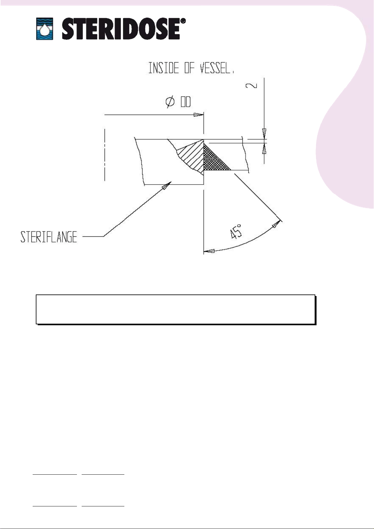
5. Makingand Preparation ofHolein theGable
1. MeasuretheouterdiameteroftheSteriflange.
2. Mark outthemeasured diameteron theoutsideofthelowergableend.
3. Cutaholewith theaid ofaplasmacutter, followingthemarked size on thegableend.
4. Prepareasuitableweld gapbetweenthegableendand theflangebygrindingtheedgeofthe
hole. Thisweld grooveshould bekeptassmall aspossible. Theflange can beused asatemplate.
5. Preparetheholeforweldingbygrindinga45°angle,slopingoutwards,seethefigurebelow.A
straightedge about2 mm should beleft towardstheinsideofthevessel.
6. Welding(TIG), tack weldingtheSteriflange
7
STERIDOSESALES
HeadOffice
Himmelsbodavägen 7·P.O.Box120 ·SE-147 22 TUMBA ·SWEDEN
Phone:+46-844999 00 ·Fax: +46-8449 99 90
info@steridose.com · www.steridose.com
RegionalOffice
5020 WorldDairyDrive ·Madison,WI53718 ·USA
Phone:+1-608 229 5225 ·Fax:+1-608 227 9599
info@steridose.com · www.steridose.com
IMPORTANT!
Allowthegableand theflange to cool slowlyon completion ofwelding.
No coolingmedium, otherthan airhasto beused.
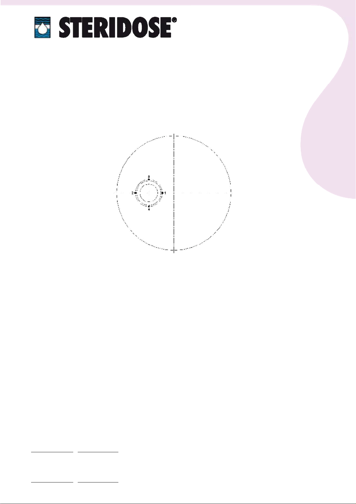
1. Check thatstampedchargenumberon theSteriflange isidentical to thenumberon certificate.
2. Position theflange in theholeso thattheinnersurface isflush with theinnergablesurface.
3. Tackweld theflangewithaTIGwelderattwopointson theinside,(point1and point2inthe
figurebelow).Thecorrectfillerdependson thematerialin thegableandflange.Foragableand
flange of316LfillerAvesta316L(SKR), 316L-Si/SKR-Si orsimilarisrecommended.
8
STERIDOSESALES
HeadOffice
Himmelsbodavägen 7·P.O.Box120 ·SE-147 22 TUMBA ·SWEDEN
Phone:+46-844999 00 ·Fax: +46-8449 99 90
info@steridose.com · www.steridose.com
RegionalOffice
5020 WorldDairyDrive ·Madison,WI53718 ·USA
Phone:+1-608 229 5225 ·Fax:+1-608 227 9599
info@steridose.com · www.steridose.com
4. Check howtheflange isfitted, itmustlieflush with theinsideofthelowergableend.
5. Tackweld theflange attwomorepointsfromtheinside(3and 4in accordance withthebelow
figure).
6. Turnoverthegableand place iton aflatbench. Sealitbetweenthebenchand gableend with
theaid oftapeetc.Fill thegableend withargon gas.Itwill normallytakeabout3or4minutes
to replace theairwith theinert argon gas. Keep acertain gasflowingduringthewelding.
7. Tack weld theflange from theoutside. Thesequence 5-16 asshown in thefigurebelowis
followed.

9
STERIDOSESALES
HeadOffice
Himmelsbodavägen 7·P.O.Box120 ·SE-147 22 TUMBA ·SWEDEN
Phone:+46-844999 00 ·Fax: +46-8449 99 90
info@steridose.com · www.steridose.com
RegionalOffice
5020 WorldDairyDrive ·Madison,WI53718 ·USA
Phone:+1-608 229 5225 ·Fax:+1-608 227 9599
info@steridose.com · www.steridose.com
7. Final Welding
IMPORTANT!
Allowthegableand theflange to cool slowlyon completion ofwelding.
No coolingmedium, otherthan airhasto beused.
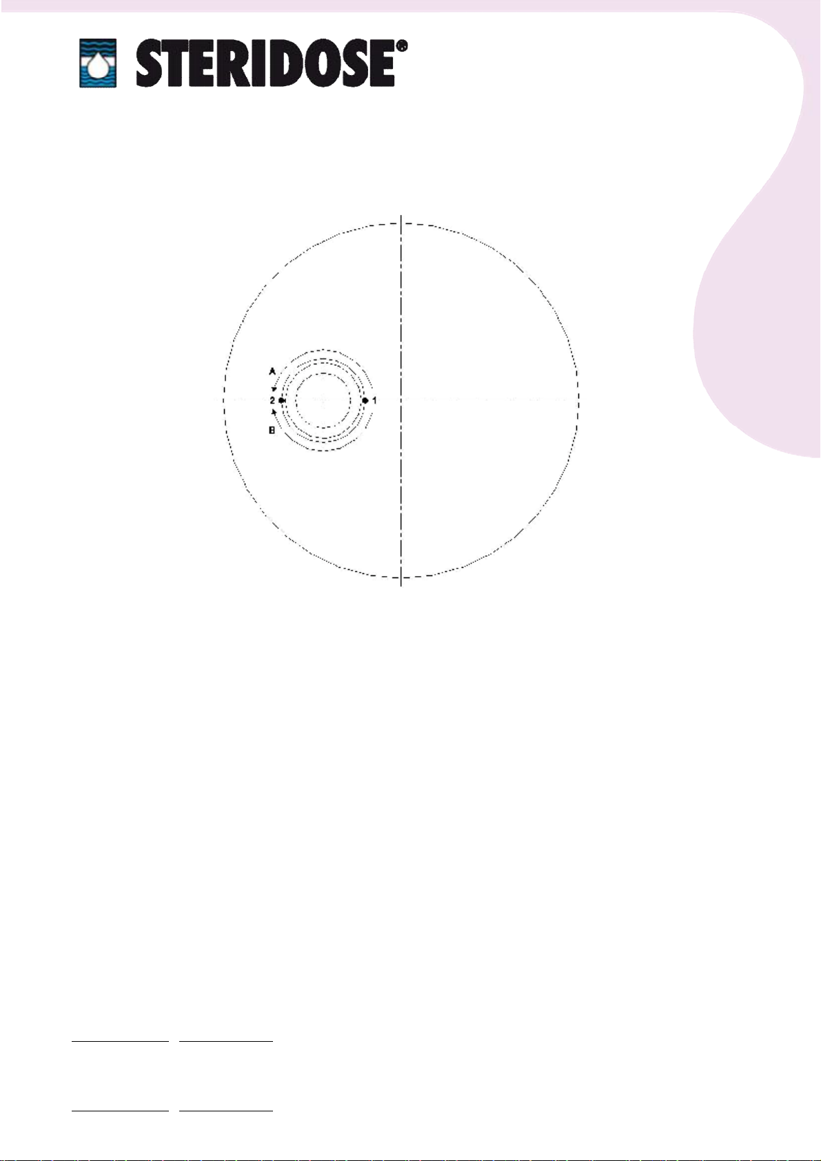
Thefinalweldingstartsnearesttothecentreofthegable.Itshould beweldedcontinuouslyfrom
point1topoint2(alongpathAasshownin thefigurebelow).A1,0 mm wireand weldingcurrent
should beusedwhen weldinga5mm thickgable.Thefillermaterialshould bethesameasthatused
previously.
Weldingshould bedonewithoutinterruption. Thesecond halfofthecirclefrom point1topoint2
butalongpath Bisnowwelded. Otherwisethesameasabove.
Theweldingisfinishedwiththesameprocedureasabovefrom point1topoint2(butalongpath
A),from 1to2(alongpathB),from 1to2(alongpathA),from 1to2(alongpathB).......... until the
weld ditch isfilled.
Thegableshould beinvertedagain and weldedfrom theinsidetoevenouttheweld joint.ATIG
qualified weldermustbeused throughoutforwelding.
10
STERIDOSESALES
HeadOffice
Himmelsbodavägen 7·P.O.Box120 ·SE-147 22 TUMBA ·SWEDEN
Phone:+46-844999 00 ·Fax: +46-8449 99 90
info@steridose.com · www.steridose.com
RegionalOffice
5020 WorldDairyDrive ·Madison,WI53718 ·USA
Phone:+1-608 229 5225 ·Fax:+1-608 227 9599
info@steridose.com · www.steridose.com
8. AfterWelding
1. Allowthegableand theflange tocool slowlyoncompletion ofwelding.Nocoolingmedium,
otherthan airhasto beused.
2. Grind and polish theinsideand outsideoftheweld to therequired finish.
Steriflange®isaregistered trademark.
Table of contents
Popular Welding System manuals by other brands


 Operator's manual")


ESAB
ESAB Aristo Mig U5000i 400 V instruction manual

STAYER WELDING
STAYER WELDING M40.18Multi operating instructions

Miller Electric
Miller Electric 230Volt owner's manual

ESAB
ESAB DTG 405 Service manual

Eastwood
Eastwood VERSA-CUT 60 Assembly & operating instructions

Miller
Miller Auto-Continuum 350 CE owner's manual