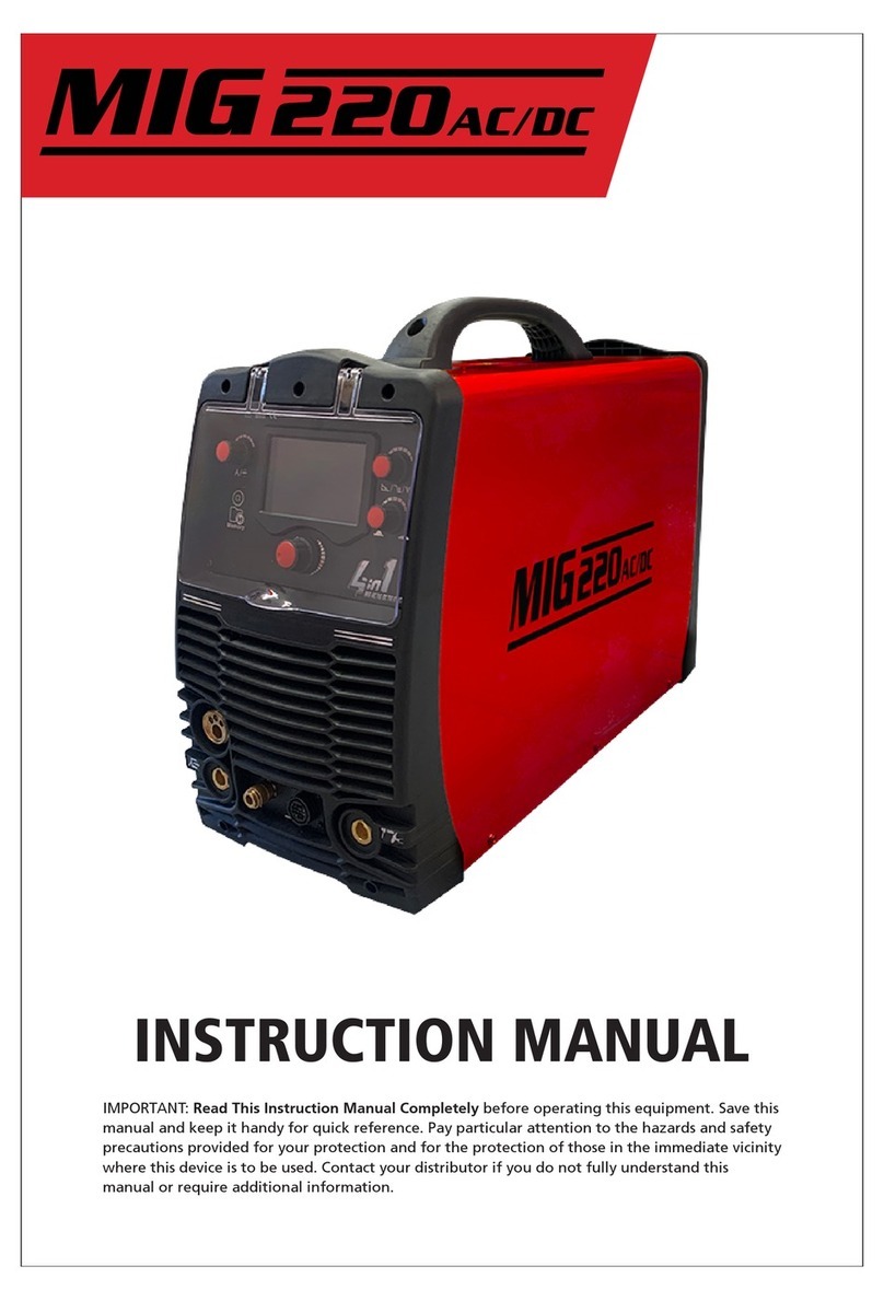
GWS ARC400 User manual

INSTRUCTION MANUAL
IMPORTANT: Read This Instruction Manual Completely before operating this equipment. Save this
manual and keep it handy for quick reference. Pay particular attention to the hazards and safety
precautions provided for your protection and for the protection of those in the immediate vicinity
where this device is to be used. Contact your distributor if you do not fully understand this
manual or require additional information.
400

© 2021 Global Welding Supplies, Ltd (GWS)
All rights reserved
The information in this manual may be reproduced for personal or in-house use without permission from
GWS. Otherwise, no part of this manual may be reproduced in any material form or transmitted to any
persons without permission from GWS or as permitted under the New Zealand Copyright Act 1994.

1
Contents
Features
1.0 Recommended Safety Precautions ................. 2
1.1 Personal Safety Warning Signs .............................. 2
1.2 Arc Welding Risks ................................................... 2
1.3 Electrical Shocks ..................................................... 4
1.4 User Responsibilities .............................................. 4
2.0 Introduction ......................................................... 4
2.1 Working Principle ................................................... 5
2.2 Volt-Ampere Characteristics .................................. 5
3.0 Installation and Adjustment ............................ 6
3.1 Parameters............................................................... 6
3.2 Duty Cycle & Over Heating..................................... 6
3.3 Welding Polarity Connection Way......................... 7
3.3.1 MMA ...................................................................... 7
5.0 Warranty Schedule ............................................ 14
PLEASE NOTE that under no circumstances should your
ARC400 be altered or changed in any way from standard
factory configuration. Doing so, will void the machine
warranty.
400
4.0 Operation Control and Connectors ................. 8
4.1 Lay out For Front And Rear Panel........................... 8
4.2 Welding Current Adjustment .................................. 9
4.3 Arc Force Adjustment .............................................. 9
4.4 Adjustment of Hot Start ........................................ 10
4.5 Welding Operation ................................................ 10
4.5.1 Striking Arc.......................................................... 10
4.5.2 Manipulation of Electrode ................................. 10
4.6 Welding Parameters............................................... 10
4.6.1 Joint Form in MMA ............................................ 10
4.6.2 Electrode Selection.............................................. 11
4.7 Arc Welding Defects & Preventative Measures .... 12
4.8 Operation Environment.......... ...............................13
4.9 Operation Notices ................... ...............................13
6.0 Troubleshooting................................................. 15
7.0 Parts & Accessories............................................ 16
• DC TIG Function
• Arc Force/Hot start functions
• IGBT Inverter technology makes for a smooth and
stable welding output
• Convenient pre-setting function
• Readily portable weighing 20.5Kg
• Built in automatic protection functions for over heating,
over current/voltage etc
• Digital amp meter

1.1 Personal Safety Warning Signs
2
1.0 Recommended Safety Precautions
The above safety warning signs indicate the risk of personal
injury or even death. IMPORTANT! Hot or moving parts can
cause serious injury and electric shock can kill. Use the
following ARC400 operation guidelines to insure your own
personal safety and for those in the immediate vicinity of
your work area.
1.2 Arc Welding Risks
Ensure your personal safety and of those nearby by observ-
ing the following risks surrounding the use of this machine.
• Only qualified technicians should service, maintain or
repair your ARC400.
• Only those specifically trained in Arc welding procedures
should operate this machine.
• During operation, clear the work area of individuals not
required in the operation, especially children.
• Adhere to precautions contained in section 5. DC voltage
remains in the capacitors after the machine has been
shut off and may cause electric shocks.
• NEVER TOUCH electrical parts.
• Use dry, Arc rated gloves and other protective safety gear.
• Protect yourself from work and ground using dry
insulation. Make sure inulation is sufficiently covering
the working area.
• Use caution when working in confined spaces, in wet
environments or where falling is a risk.
CLOTHING:
Suitable clothing must be worn to prevent excessive skin
exposure to UV radiation, sparks and molten metal. Flame-
proof, loose fitting cotton clothing buttoned to the neck,
protective leather gloves, spats, apron and steel toe safety
boots are also highly recommended. In addition, use a
helmet with the recommended shade lens for amperage
listed in the shade chart below.
FUMES AND GASES CAN BE DANGEROUS:
• Welding may produce fumes and gases that are hazardous
to health. When welding, keep your head out of the fumes,
avoiding inhalation. Use enough ventilation and/or exhaust
at the arc to keep fumes and gases away from the breathing
zone. Welding with electrodes require special ventilation
such as stainless/hard facing or on lead/cadmium plated steel
along with other metals or coatings which produce highly
toxic fumes. Keep exposure as low as possible and below
Threshold Limit Values(TLV) using local exhaust or mechani-
cal ventilation. Within confined spaces or in some circum-
stances - outdoors, a respirator may be required. Additional
precautions are also required when welding on galvanized
steel.
• Do not weld in locations near chlorinated hydrocarbon
vapors; which are a result of degreasing, cleaning or
spraying operations. The heat and rays of the arc can react
with solvent vapors to form phosgene - a highly toxic gas.
• Shielding gases used for arc welding can displace air and
cause injury or death. Always use enough ventilation,
especially in confined areas, to insure breathing air is safe.
• Read and understand the manufacturer’s instructions for
this equipment and the consumables to be used, including
the material safety data sheet. Adhere to your employer’s
safety practices.
ARC RAYS CAN BURN:
• Use a properly filtered shield with cover plates to protect
your eyes from arc rays and sparks when welding or when
observing open arc welding.
Less than 150 amps
150 to 250 amps
250 to 300
300 to 350
Use one shade darker for aluminium welding
Shade 9
Shade 10
Shade 11/12
Shade 13
ELECTRIC SHOCK CAN KILL!
400
• DC TIG Function
• Arc Force/Hot start functions
• IGBT Inverter technology makes for a smooth and
stable welding output
• Convenient pre-setting function
• Readily portable weighing 20.5Kg
• Built in automatic protection functions for over heating,
over current/voltage etc
• Digital amp meter

3
ROTATING PARTS MAY BE DANGEOUS:
• Use only compressed gas cylinders with the correct shield-
ing gas for the process that is to be used and ensure the
appropriate designed regulators are installed correctly. All
hoses, fittings, etc. should be suitable for the application
and should be in good working condition.
• Always keep cylinders in an upright position and securely
fasten these to an undercarriage or a fixed support.
• Cylinders should be located:
- Away from areas where they could be struck or be
subjected to physical damage.
- A safe distance from arc welding or cutting operations
and any other source of heat, sparks, or flame.
• Never allow the electrode, electrode holder or any other
electrically “hot” parts to touch a cylinder.
• Keep your head and face away from the cylinder valve
outlet when opening the cylinder valve.
• Valve protection caps should always be in place and hand
tightened except when the cylinder is in use or connected
for use.
ELECTRIC AND MAGNETIC FIELDS:
Electric current flowing through any conductor causes
localized Electric and Magnetic Fields (EMF). When and
where possible, you should minimize exposure to EMF as
much as possible.
In order to minimize EMF, here are a few steps we recom-
mend you follow:
• Route the electrode and work cables together – Secure
these with tape wherever possible.
• All cables should be put away and kept at a safe distance
from the operator.
• Never coil the power cable around your body.
• Make sure the welding machine and power cable are as
far away from the operator as possible.
• Connect the work cable to the workpiece as close as
possible to the area being welded.
• People with heart pacemakers should keep a safe distance
away from the welding area.
The equipment complies with the Class A electromagnetic
compatibility which is intended for users in locations other
than residential locations where the electrical power is
provided by public low-voltage supply system.
• Use suitable clothing made from durable flame-resistant
material to protect your skin and that of your assistants
from the arc rays.
• Protect nearby personnel with a suitable, non-flammable
screen and/or warn them not to watch the arc, hot spatter
or the metal.
WELDING SPARKS CAN CAUSE FIRE OR EXPLOSION.
• Remove all fire hazards from the welding area. In the
event this is not possible, cover them with fire-retardent
material to prevent the welding sparks from generating a
fire. Important Reminder: Welding sparks and hot materials
can easily fall through small cracks and openings in adjacent
areas. Avoid welding near hydraulic lines and have a fire
extinguisher readily available.
• Where compressed gases are to be used at the job site,
special precautions should be used to prevent hazardous
situations.
• When not welding, make certain no part of the electrode
circuit is touching the work or ground. Accidental contact
can cause overheating and create a fire hazard.
• Do not heat, cut or weld tanks, drums or containers until
the proper steps have been taken to insure that such
procedures will not cause flammable or toxic vapors from
combusting substances inside. They can cause an explosion
even though they have been “cleaned”.
• Vent hollow castings or containers before heating, cutting
or welding. If you do not, this could lead to an explosion.
• Connect the earth lead cable to the work as close to the
welding area as practical. Earth Lead cables connected to
the building framework or other locations away from the
welding area increase the possibility of the welding current
passing through lifting chains, crane cables or other alter-
nate circuits. This can create fire hazards by overheating the
lifting cables until they fail.
400

1.3 Electrical Shock
• Never touch ‘live’ electrical parts.
• Earth clamp all work materials.
• Never work in wet or damp environments.
Avoid electric shock by:
• Wearing dry, insulated boots.
• Using dry, leather gloves.
• Never change an electrode with bare hands or wet gloves.
• Never cool electrode holders in water.
• Work on a dry, insulated floor where possible.
• Never hold the electrode or its holder under your arm.
1.4 User Responsibilities
• Read the Instructional Manual prior to using your
ARC400.
• Unauthorised repairs to this equipment may endanger
the technician/operator and will void your Warranty.
Only qualified personnel should perform repairs.
• Always disconnect the main power source before investi-
gating equipment malfunctions.
• Replace broken, damaged, missing or worn parts & hoses
immediately.
• Equipment should be cleaned & serviced periodically.
4
2.0 Introduction
WELDARC Arc Series welders are general MMA arc welders
which adopt the latest pulse width modulation (PWM)
technology as well as an insulated gate bipolar transistor
(IGBT) power module. This state-of-the-art technology will
change the work frequency to medium frequency so as to
replace the traditional hulking work frequency transformer
with the cabinet medium frequency transformer. These
machines are readily portable thanks to their small size and
light weight.
WELDARC Arc Series machines are excellent performers.
They have a constant current output which makes arc
welding stable and the fast dynamic response speed will
reduce any impact from the arc length fluctuations. There
are also automatic protection features to avoid any
under-voltage, over-current, and/or over-heating which
might occur inside the welders. When these issues occur, the
alarm on the front panel will illuminate and the output
current will be cut. These safety features can prolong the
machine’s life and greatly improve the reliability of the
welders.
WELDARC Arc Series welders can also perform DC TIG
welding. Keep in mind that with TIG welding, the minimum
current will output first and then rise until the arc is ignited
by the lifting method. When performing MMA welding, if
the electrode touches the workpiece for more than two
seconds, the welding current will automatically drop to the
minimum current so as to protect the electrode.
MMA Manual Metal Arc welding
PWM Pulse Width Modulation
IGBT Insulation Gate Bipolar Transistor
400

5
2.1 Working Principle
The working principle of WELDARC Arc welders is shown in
the flowchart below.
The single phase 110V-220V±10% work frequency (50/60 Hz)
AC is rectified into DC which is then converted to a medium
frequency AC (approx. 20K-40KHz) by using an inverter
device (IGBT module). The voltage is further reduced by
using a medium transformer (the main transformer) and
then rectified by using a medium frequency (fast recovery
diode), which is then is outputted by inductance filtering.
The circuit adopts current feedback control technology to
ensure current output stability. The welding current
parameter can also be adjusted continuously to meet
welding requirements.
Three Phase, AC
380V (50Hz) Rectify
DC
DC
AC
AC
Inverter
Medium
frequency
transformer
Medium
frequency
rectify
Hall device
Current positive-
feedback control
2.2 Volt-Ampere Characteristic
WELDARC Arc Series welders have excellent volt-ampere
characteristics as displayed in the following graph.
With MMA welding, the relation between the rated loading
voltage U2and welding current I2is as follows:
When I2 ≤ 600A,U2=20+0.04 I2
(V);
When I2 >600A,U2=44(V).
DC
400

6
3. Installation & Adjustment
3.1Parameters
Note: The above parameters are subject to change with the improvement of machines.
3.2 Duty Cycle & Over heating
Refer to the diagram on the right. The vertical axis “X” stands for
duty cycle, which is defined as the proportion of time that a
machine can work continuously within a certain timeframe(10
minutes). Horizontal axis I is the output current in amperage(A).
The relation between the duty cycle “X” and the output welding
current “I” is shown in the figure to the right.
If the welder overheats, the IGBT over-heat protection unit inside
will cut the output welding current to the minimum and illumini-
ate the over-heat pilot lamp on the front panel. In the event this
occurs, the machine should be left to idle for 15 minutes allowing
the fan to cool the machine. Before operating the machine again,
try reducing the welding output current and/or the duty cycle.
Take special care and monitor the over-heat lamp on the panel.
x
I(A)
100%
60%
0
The relation between duty cycle and
welding current of the ARC400
300 400
400
ARC 400Machine
Power Supply Voltage (V)
Dimensions (mm)
Frequency (Hz)
Rated Input Power (KW)
Rated Input Current (A)
3~380/400/415/440±10%
50/60Hz
40%400A
60%330A
89
Duty Cycle (40°C 10min)
Welding Current Range (A)
Efficiency (%)
Power Factor
Net Weight (Kg)
470x250x400
0.95
IP23
27
F
Protection Class
Insulation Class
No-Load Voltage (V)
16.9
16.9
5~400
15(VRD)
MMA TIGFunction
12.6
26.7 19.9
Effective Current (A) 12.6
100%250A
85
2.5, 3.2, 4.0, 5.0
Electrode Diameter
AF
Cooling
General Purpose, Low Hydrogen, Stainless, Mild Steel,
High Tensile, Cast Iron, Hard Facing, Dissimilar Metals·
Electrode Type

7
3.3 Welding polarity connection way
3.3.1 MMA
Workpiece
-+-+
ARC400 ARC400
Holder
Workpiece
Holder
Electrode Electrode
DCEN DCEP
Choosing the connection of DCEN or DCEP is based on the arc stable burning condition. Different
electrodes need different connections. Please refer to the electrode manual.
400

4.1 Layout for front & rear panel
4.0 Operation control and connectors
6
1
3
5
9
1. Power pilot lamp This pilot lamp, when lit, indicates that the machine is on.
2. Alarm pilot lamp This pilot lamp, when lit, indicates protection of the machine has been activated.
3. Welding current regulation Set welding current
4. Conversion switch Choose (right), MMA.
Choose (left), TIG.
5. Voltage/current selection To select voltage/current display.
6. Voltage current display
7. Hot start adjustment
8. Arc force adjustment
9. Output Joint Negative polarity output.
10. Output Joint Positive polarity output.
11. Main switch
12. Mains cable
13. Cooling fan
8
13
28
7
4
10
12 11
400

9
4.2 Welding Current Adjustment
WELDarc Arc Series welders have the function to
pre-set welding currents. Before operating, adjust the
welding current, which will then display the output in
ampere. It is convenient to set parameters and adjust
accurately.
400
5% 100%
CURRENT
A
4.3 Arc Force Adjustment
When the ARC400 load voltage is under 20V, there is
arc force output. The arc length is shorter and the arc
force is bigger. It can prevent sticking and increase the
depth of penetration.
The numbers “0-10” on the potentiometer is not
actual arc force, but a proportion concept.
When the potentiometer is in the “0” position (the
minimum of the arc force), the operation of arc force
is not in use.
Operation remark
-In the mark of 0 (soft arc), application range: acid
electrode; in the middle & high current, using basic
electrode.
-In the mark of 10 (hard arc), application range:
welding in the low current range(vertical up welding,
surfacing welding, overhead welding, etc.)
0 10
19
8
7
6
4
5
3
2
Increase the arc force:
• Easy to strike arc
• Increase spatter
• Good root meltability
• Welding thin plate increases the dangers of
penetration
Welding Position
Flat welding for
flat plate butt
joint
Vertical welding
for flat plate
butt joint
Horizontal fix
welding for pipe
butt joint
Vertical fix
welding for pipe
butt joint
Workpiece thickness (mm)
Continuous
welding
Intermittent
welding
Gap (mm)
Root face size
(mm)
Electrode
diameter (mm)
Backing welding
current (A)
Gap (mm)
Root face size
(mm)
Electrode
diameter (mm)
Backing welding
current (A)
2.5~3.2
~
3.2
70~80
3.2~4
1~1.5
3.2~4
80~110
2.5~3.2
~
3.2
75~85
3.2~4
1~1.5
3.2~4
100~110
2.5~3.2
~
2.5
60~70
3.2~4
1~1.5
3.2
90~110
2.5
~
2.5
70~80
2.5~3.2
1~1.5
3.2
90~110
8~12 8~12 Ф114x17 Ф114x17

4.5 Welding Operation
4.5.1 Striking Arc
Knocking arc: Position the electrode upright and
touch the workpiece, Once the short circuit has been
created, quickly lift up about 2~4 mm, and an arc will
be ignited. This method is difficult to master. But
when welding brittle or hard steel, it is better to use
the knocking method.
Workpiece
Electrode Upright
Workpiece
Electrode
Touch
Take the electrode upright Touch the electrode
to the workpiece
Workpiece
Electrode
Up
2-4mm
Lift the electrode around 2-4mm
Scratch Start the electrode along the workpiece to
initiate the striking arc.
4.5.2 Manipulation of Electrode
Workpiece
Weld
Electrode
1. Electrode Moving
2. Electrode swing right & left
3. Eletrode movement along the weld
In MMA welding, there are three motions being
matched on the end of the electrode: the electrode
moving to the molten pool along the axis, the
electrode swinging right/left and the electrode
moving along the welding way.
The operator can choose the manipulation of
electrode based on the welding joint sharpness,
welding position, electrode spec, welding current
and/or operation skill, etc.
4.6 Welding Parameters
4.6.1 Joint form in MMA
In MMA welding, the common basic joint form is: butt
joint, lap joint, corner joint & T joint.
Butt joint
T joint
Corner joint
Lap joint
0 10
19
8
7
6
4
5
3
2
4.4 Adjustment of Hot Start
The number ”0~10” on the potentiometer is not
actual arc force, but a proportion concept.
Turning the hot start knob clockwise increases the hot
start current duration and makes for easier striking.
There are no actual added current values around the
knob. Hot start adjustment is chosen to be based on
the electrode diameter and workpiece thickness.
Operation remark
• It is available in the striking arc only.
• The interval time for hot start is 3 sec.
10

11
The electrode diameter selection is based on the workpiece thickness, welding position, joint form, welding layer,
etc. Please refer to the following table.
Workpiece thickness/mm
Welding current/A
The relation between the welding current(I)’ factor(K) & electrode(d) (I=K*d: Carbon electrode)
The welding current reference for different electrode diameters
Electrode diameter/mm
Factor/K
1.6
1.6
2.5 3.2
25~40 50~80 100~130
2~2.5 3.2
20~25 25~30 30~40
• The electrode should be dried according to the appropriate user’s manual before use. This is necessary to
reduce the hydrogen of the molten pool and welding seam, and to avoid blowhole and cold crack.
• In the welding process the arc must not be too long, otherwise it will cause unstable arc burning, large
spatter, light penetration, undercut, blowhole, etc. If the arc is too short, it will cause the electrode to stick.
• In MMA welding the arc length is usually equal to 0.5~1.0 of the electrode’s diameter. The basic
electrode’s arc length should not be beyond the electrode’s diameter, so it’s better to choose short arc welding.
400
4~6
40~50
Workpiece thickness/mm
Electrode diameter/mm
The relation between the electrode diameter & workpiece thickness
2 3 >13
23.2 4~6
1.6
25~40
4.0
160~210
5.0
200~270
5.8
260~300
4~5 6~12
3.2~4 4~5
4.6.2 Electrode Selection

12
4.7 Arc Welding Defects & Preventative Measures
Issue Cause Preventative measures
Choosing the proper groove angle & assembly gap,
improve the assembly quality.
Choosing the proper welding parameters.
Improve operation skills.
Choosing the proper welding current & speed.
The arc should not be drawn too long.
The electrode angle should be correct.
Manipulation of electrode should be correct.
Correctly choose and process the groove size.
Correctly assemble and ensure clearance.
Choose suitable welding current & speed.
Improve operation skills.
Choose the correct welding parameters.
Enhance the clearness of layers.
Choose parameters based on the welding position.
Strictly control the molten hole size.
In the crater, the electrode should remain only for a short
time in order for the electrode to be manipulated.
After the molten pool is filled in with metal, move to the
side to avoid a crater.
Clear the dust around the groove(approx 20-30mm either side).
Dry the electrode according to manual.
Correctly choose parameters to operate.
Use the short arc operation.
Welding location in the field should have protection from the wind.
Don’t use an invalid electrode.
Choose an electrode with good slag detachability.
Strictly clear the slag in the layers.
Correctly choose the welding parameters.
Adjust the electrode angle and manipulation method.
Strictly control the percentage of S and P in the welding
material.
Adjust the structure of the welding material.
Adopt a basic electrode.
Use a basic electrode with low hydrogen.
Bake using the instructions before use.
Remove any impure matter before use, reduce the
percentage of hydrogen.
Adopt the appropriate parameters and heat input.
After welding, perform dehydrogenation.
The groove angle is incorrect.
The root face and assembly gap is not equal.
Welding techniques parameters
are unreasonable.
The welder’s operation skill is low.
Over current.
Arc length is too long.
The electrode angle is wrong.
Manipulation of electrode is incorrect.
The groove angle or gap is too small,
the root face is too big.
Welding parameters are not suitable, or
the assembly is not good.
The welder’s operation skill is low.
The welding thermal input is too low.
There is rust & dust on the side of groove.
The slag between the layers is
not cleared well.
The temperature of molten pool is
too high.
The liquid metal concretes slowly.
The crater time is short lasting.
Over current in the welding of thin plate.
There is residue like oil, rust or
water on the work piece surface and groove.
The coating of electrode is damped & not drying.
Under current or over speed when welding.
The arc is too long or lean burning, the molten
pool protection is not good.
Over current, the coating of electrode falls off
and loses protection.
Manipulation of electrode is incorrect.
The slag clears bad in the middle layer in the
welding process.
Under current or over speed when welding.
Welding operation is incorrect.
The welding material can not match the work
piece.
The groove design & processing are not proper.
During the process of solidification, the
inter crystal segregation is caused.
At the same time, with the
effect of welding stress, the hot crack is formed.
Three reasons will cause cold crack:
The structure turned from the martensite.
The residual stress caused by big
restraint intensity.
The residual hydrogen in welding gap.
Welding seam
doesn’t meet the
requirement
Undercut
Incomplete
penetration
Incomplete
fusion
Overlap
Crater
Blowhole
Inclusion & slag
inclusion
Hot crack
Cold crack
400

4.8 Operation Environment
13
• 0m to 1000m above sea level
• Operation temperature range:-10°C~+40°C.
• Relative humidity is below 90%(+20°C).
• Inclination of power source not to exceed 15 degrees.
• Protect the machine against heavy rain or hot
direct sunlight.
• The content of dust, acid, corrosive gas in the surrounding
air or substance can not exceed normal standards.
• Take care that there is sufficient ventilation.
• There is at least 30cm freee distance between the machine
and wall surrounding walls.
• Read section 1 carefully before attempting to use
this equipment.
• Connect the ground wire with the machine directly.
• Input power must be AC as three phases, 50Hz 380V.
• In case of closing the power switch, no-load voltage
may be exported. Do not touch the output electrode
with any part of your body.
• Do not watch the arc without eye protection.
• Ensure good ventilation of the machine to improve
duty ratio.
• Turn off the engine when the operation is finished to
reduce the amount of energy sources.
• When the power shuts down automatically due to an
overheating(or other) issue, don’t restart the machine
until the problem is resolved. Otherwise, the range of
potential problems will be exacerbated.
4.9 Operation Notices
400

5.0 Warranty Schedule 2021
GWS welding equipment is designed and tested for professional industrial environments.
As a guarantee of high quality, we offer a warranty. Valid only from the sale by GWS or an accredited distributor of the
equipment or product.
In no event shall the warranty period extend more than the time stated. The warranty period includes parts and labour.
GWS reserves the right to request documented evidence of the date of purchase.
Warranty terms are for single shift operation on all equipment and product. Warranty terms are a back to base warranty.
All costs associated with lodging the warranty claim, including the return of goods to the Accredited Service Provider, are
the responsibility of the consumer.
Any claim under this warranty must be made within the warranty period which commences on the date of purchase on the
equipment or product. For the warranty to be approved the equipment or product has to be assessed by accredited GWS
personnel.
Any modifications or alterations made to the equipment or product including electrical modification will result in the
equipment or product not being covered under warranty. Any failures under the warranty period that are due to incorrect
operation of the equipment or product will not be covered under warranty.
Consumers are reminded to only use the product in accordance with the operating instructions.
For additional operating instructions or to make a warranty claim call 0800 536 774
Main transformers - Output
inductors
3 years
Power sources - Wire feeders -
Cooling units
2 years
Cooling pumps - Automa�on
products - Ven�lators - Main
contactors - Wire feeder
motors - Solenoid valves -
Welding Masks (welding
helmet)
1 year
Mig, Tig & Plasma Torches
Work leads, electrode holders
3 months
Mig, Tig, Plasma consumables,
Welding consumables
Nil
Gas Regulator brass body
2 years
Flowmeter, elastomer seals, O
rings, gauges
1 year
14

15
When the machine is powered
on, the fan works but the
power light is not on.
Light damaged or has a bad
connection.
Power PCB Failures.
Test/repair the inside circuit of power
light Pr3.
Repair or change power PCB Pr2.
When the machine is powered
on, the power light is on
but the fan doesn’t work.
There is something in the fan.
The fan motor is damaged.
Clean the fan.
Change fan motor.
When the machine is powered
on, neither the fan or power
light work.
No input voltage. Check whether there is input voltage.
Over Voltage (input voltage is
too much or too little).
Check input voltage.
No no-load voltage output. There is trouble inside
the machine.
Check the main circuit, Pr1 & Pr2.
No current output.
Welding cable is not
connected with the two
outputs of the welder.
Welding cable is broken.
Earth cable is not connected
or loosened.
Connect the welding cable to the
welders output.
Wrap, repair or change the welding
cable.
Check the earth clamp.
Not easy to start arc when
welding, or easy to cause
sticking.
Earth cable is not connected
or loosened.
Earth cable is not connected
or loosened.
Earth cable is not connected
or loosened.
Earth cable is not connected
or loosened.
Earth cable is not connected
or loosened.
Earth cable is not connected
or loosened.
The arc is not stable
during welding. The arc force is to small. Increase the arc force.
The welding current can
not be adjusted.
The welding current
potentionmeter in the front
panel has a bad connection
or is damaged.
Repair or change the potentionmeter.
The penetration of the molten
pool is not enough (MMA).
The welding current is
adjusted too low.
The arc force is adjusted
too small.
Increase the welding current.
Increase the arc force.
Arc blow.
Airflow Disturbance.
The electrode eccentricity.
Magnetic effect.
Use the shelter from airflow.
Change the electrode.
Incline the electrode to the opposite
direction of the magnetic blow.
Change the position of earth clamp.
Use the short arc operation.
The alarm light is on.
Over heat
protection.
Over current
protection.
Over welding
current
Working time
too long.
Unusual current
in the main
circuit.
Induce the welding current output.
Induce the duty cycle (interval work).
Test and repair the main circuit
and drive PCB (Pr1).
1
2
3
4
5
6
7
8
9
10
11
S/N Troubles Reasons Solutions
6.0 Troubleshooting
400

SAH1000F ArcOne Vision Welding
Helmet Black 1000F
WHOTBOX WELDARC®5Kg Variable
Temperature Electrode
Hot Box
WHTOBOX
PE2
WELDARC®10Kg Variable
Temperature Electrode
Hot Box
WSAL2504 WELDARC®ARC Lead
OKC Male 500 Amp
4 Meters 35-50mm
WBRUSHCMS Wire Universal Brush
VIP1000F Mild Steel
Crevice
WSEL5004 WELDARC®Earth Lead
OKC Male 500 Amp
4 Meters 35-50mm
SWFU
WELDARC®Chipping
Hammer Plastic Handle
WCHR
SAFETYARC®Blue
Proban Welders Hood
SGMGL,
SGMGXL
MIGARC®Gold Welding
Gauntlet 40cm L/XL
(6/Pkt)
Package Includes
Optional Extras
Parts & Accessories
Product code: WM400P
400
WELDarc® E7016TC Premium Low Hydrogen
Arc Welding Electrodes 2Kg/Pkt
WEL7016252
WEL7016322
WEL7016402
2.5mm, 2kg
3.2mm, 2kg
4.0mm, 2kg
SGMGLL,
SGMGLXL
MIGARC®Green Long
Gloves 59cm L/XL
(6/Pkt)
WELDarc® E7018 Premium Low Hydrogen
Arc Welding Electrodes 2kg/Pkt
WEL7018252
WEL7018322
WEL7018402
2.5mm, 2kg
3.2mm, 2kg
4.0mm, 2kg
Superon Electrode Stainless E316L-16
WES6162002
WES6162502
WES6163202
2.0mm, 2kg
2.5mm, 2kg
3.2mm, 2kg
WES6164002
WES31632HP
WES31625HP
4.0mm, 2kg
3.2mm, Handy pack
2.5mm, Handy pack
WELDarc® Blue E6013 General Purpose
Electrodes
WEGP2502VD
WEGP4005VD
WEGP3205VD
2.5mm, 2kg
3.2mm, 5kg
4.0mm, 5kg
WBRUSHCSS Wire Universal Brush
VIP1000S Stainless
Steel Crevice
WBRUSH4MS Wire Brush 4 Row Mild
Steel Wooden Handle
WBRUSH4SS Wire Brush 4 Row
Stainless Steel Wooden
Handle
Table of contents
Other GWS Welding System manuals
Popular Welding System manuals by other brands

Migatronic
Migatronic DELTA 140 E instruction manual

Hobart Welding Products
Hobart Welding Products STICKMATE 235 AC owner's manual

SincoSald
SincoSald NOVAMIG 353C DP-MV G.R.3 instruction manual

Eastwood
Eastwood MIG 140 Assembly and operating instructions

ESAB
ESAB MEF 44N instruction manual

Thermal Dynamics
Thermal Dynamics cutmaster A60 operating manual

Kobewel
Kobewel PC 70i operating manual

Lincoln Electric
Lincoln Electric LINC 405-SA Operator's manual

Car-O-Liner
Car-O-Liner CM 193 user guide

Cebora
Cebora MIG 2060 MD instruction manual

Miller
Miller MigMatic 300 owner's manual

Westermans International
Westermans International FAST SPOTTER 3.5 Installation, operating and maintenance manual