Steril-Aire Enhanced UVC Kit User manual

1
Installation and Operation Instructions
NOTE: Read this entire instruction sheet before starting the installation.
IMPORTANT CONSIDERATIONS
Improper installation, adjustment, alteration, service,
maintenance, or use can cause fire, electrical shock, or
other conditions which may cause personal injury or
property damage. Consult your supplier or Steril-Aire for
information or assistance.
Understand the signal words DANGER, WARNING, and
CAUTION. These words are universally used for overall
safety. DANGER identifies the most serious hazards which
will result in severe personal injury or death. WARNING
signifies hazards which could result in personal injury or
death. CAUTION is used to identify unsafe practices
resulting in minor personal injury or product and property
damage.
WARNING:
Before performing maintenance or service on fixture,
ensure unit is unplugged. Electrical shock can cause
injury or death.
CAUTIONS:
•
Never expose eyes or skin to UVC light. Wear gloves,
face shield/glasses (per ANSI Z87.1) and cover all
exposed skin.
•
Do not touch UVC Emitter®germicidal lamp without
gloves. Damage to Emitter may result. Oil from
fingerprints will permanently etch glass of Emitter and
weaken structure. If necessary, clean Emitter using a
Steril-Aire cleaning kit, isopropyl alcohol and a lint-free
wipe may be substituted.
•
UVC Emitters are fragile. To prevent accidental
breakage handle the UVC Emitter with care.
•
Voltages outside of the range designed for the unit
will void the warranty and do permanent damage to
the entire unit.
•
Emitter contains a small quantity of mercury.
If an Emitter breaks, clean and dispose of with the
same care as a fluorescent lamp.
•
UVC energy may cause damage to non-metallic
components. Such components shall be protected
with UV resistant material such as aluminum foil,
aluminum duct tape, metallic shields, etc.
•
The qualified installer or agency must use factory
kits and accessories when installing this product.
For your safety ensure that the Kit is electrically
connected to a proper power source, on/off switch,
interlock switch (or control panel) and fuse.
Upon completing the installation, the UVC Emitters
should be operated continuously, 24/7, to preclude
the development of mold and bacteria.
Dispose of used Emitters in accordance with local
regulations regarding the disposal of fluorescent
lamps.
Enhanced UVC Kit
Part Number: 10000180-1
Patents 5,817,276/ 6,245,293/ 6,267,924/ 6,280,686/ 6,313,470/ 6,423,882/ 6,500,267
/6,589,476/ 6,627,000/ 6,783,578/ 7,140,749/ 7,282,728/ 7,459,694 & others pending
Made in the USA

2
INSTALLATION &OPERATION
NOTE: Ensure that Emitter is installed before
power is applied. Installing Emitter after power has
been applied may trigger the
“
end-of-lamp-life c
ir
c
uit
”
and the Emitter may
fa
i
l
to light. If this happens, shut
off power for
10
seconds and then turn power back on.
Emitter will then
l
i
g
ht
..
CAUTION: Do not drill into coil, refrigerant lines
or other mechanical equipment. Consult all applicable
codes before installing. Check power supply housing
label for the correct power requirements. Obtain power
from a suitable, protected (fused) and grounded power
source.
The Enhanced UVC Kit is comprised of the following
components:
A Power Supply with an M12 Recepticle, A 3 foot
Emitter Connection Cable (with an IP67 Connector &
M12 plug), and two Spring Clips.
Emitters are not included but sold separately
INSTALLATION SPEC
I
FI
C
A
T
I
ONS
The Enhanced UVC Kit is installed downstream from
the coil. If downstream space is unavailable, install
upstream.
The Emitter should be at least 1” away from any
heating coil and not make contact with the AHU blower.
INSTALLATION INSTRUCTIONS
WARNING: Before performing maintenance or
service on fixture, ensure unit is unplugged.
Electrical shock can cause injury or death.
1. The Emitter access door or panel should be
interlocked (interlock switch P/N 90000120) with
the power source to turn Emitter(s) off when the
Air Handler is opened. It should have signs
(provided) alerting maintenance personnel to the
possible hazard of looking at or exposing skin to
UVC energy. Service accesses may be
equipped with a glass or Lexan® window to view
Emitters; viewports are available as an
accessory. UVC energy does not penetrate
common glass or Lexan®.
2. If applicable, remove outer cover of air handler.
3. UVC energy may damage some plastics. Wrap
suspect items with aluminum tape; use metallic
conduit or use other appropriate shielding where
these items may be in "line of sight" of the UVC
energy.
4. Determine an appropriate flat-surfaced location
for mounting the power supply. Make sure that
the Emitter Connection Cable (with extension
cord, if applicable) can reach the pins of the
Emitter and that M12 Plug can reach the M12
Recepticle at the power source; mount the
power supply. The recommended maximum
extension wire length from Emitter to power
supply is 35’ (10.67m).
5. If using the Spring C-Clips, mount the two (2)
spring C-clips on an existing panel or framing
structure facing the coil. The clips should be
attached to the Emitter on both ceramic ends.
Install Emitter ceramic into the spring clips
provided.
6. Using a qualified electrician, make the electrical
connection to the electrical cable coming from
power supply housing. Don’t turn on power.
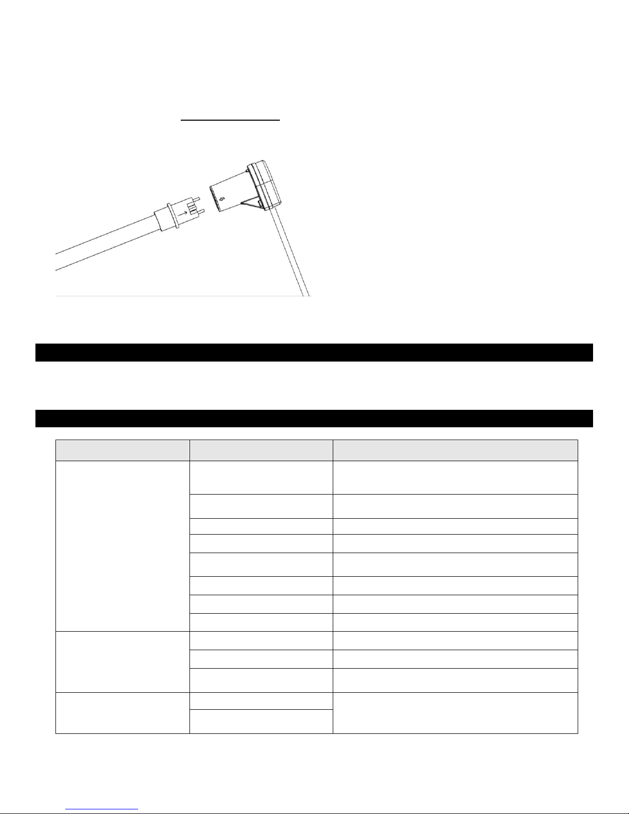
7. Connect lead socket to Emitter by aligning
arrows.
8. Screw in the M12 Plug on the wire lead to the
M12 Receptacle on Power Supply enclosure
aligning the tab & slot.
9. Complete all power connections.
10. Reconnect power to the air conditioner and
toggle the installed switch, if applicable, to the
“On” position. The Emitter should emit a bright
blue hue, indicating that it is properly powered.
11. Attach the Caution Label and Lamp Change
Date Label to air handler access panel so they
are clearly visible.
MAINTENANCE
Emitters need to be periodically replaced with Genuine Steril-Aire Emitters to maintain design output. Emitters should be
replaced after 9000 hours of use (1-year).
TROUBLESHOOTING
Symptom
Possible Causes
Corrective Action
Emitter does not light
Momentary loss of power.
Reset Power Turn off power for 10 Seconds, and
then turn power on.
Poor connection
Check connection to Emitter. Check wiring
connections. Reset Power
Incorrect wiring
Inspect circuit to wiring diagram.
Dirty pins
Clean pins. Reset Power
System malfunction
Check system components, interlock door
switches, relays, motion detectors, etc.
Emitter reaching end of life
Replace with new Emitter. Reset Power
Defective Power supply
Replace Power Supply.
Broken Filament
Replace with new Emitter. Reset Power
Visibly Weak Emitter
Light
Bad Wiring
Check wiring to Emitter
Emitter reaching end of life
Replace Emitter
Emitter too Cold
If Emitter is at or below 35°F(1°C), Emitter is too
cold to operate properly.
Red/Orange Emitter
Emitter reaching end of life
Replace Emitter
Contamination in Gas
Mixture
Thank you for choosing Steril-Aire, #1 “UVC for HVAC” solution provider worldwide. Please contact your local supplier or Steril-Aire
directly if we can provide any further information or service. Call 1-818-565-1128 or visit www.steril-aire.com. Your satisfaction is very
important to us.
© 2016 Steril-Aire, Inc. All rights reserved. 1381A
The health aspects associated with the use of this product and its ability to aid in disinfection of environment air has not been investigated by UL.
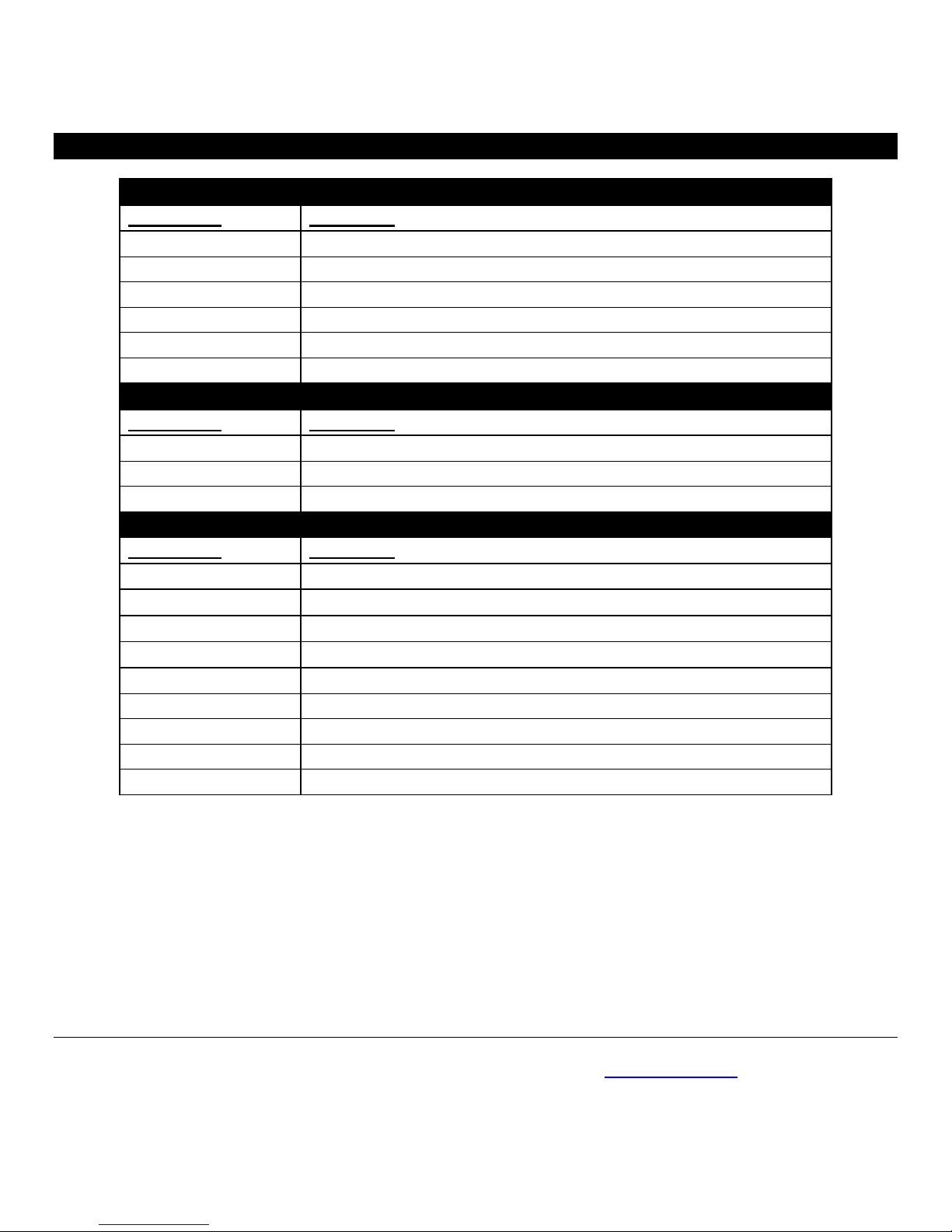
EMITTERS,REPLACEMENT PARTS &ACCESSORIES
Steril-Aire Enhanced Emitters
Part Number
Description
21000310
EGTS 24 VO - Enhanced 24" Single Ended Emitter
21000410
EGTS 30 VO - Enhanced 30" Single Ended Emitter
21000510
EGTS 36 VO - Enhanced 36" Single Ended Emitter
21000610
EGTS 42 VO - Enhanced 42" Single Ended Emitter
21000910
EGTS 50 VO - Enhanced 50" Single Ended Emitter
21000810
EGTS 61 VO - Enhanced 61" Single Ended Emitter
Replacement Parts
Part Number
Description
10000180
Power Supply Replacement for UVC Kit & RIK
90000812
Spring Clips Kit
50000130-03
Enhanced Emitter Connection Cable –3 ft.
Accessories
Part Number
Description
50000135-10
M12 Extension Cable for Enhanced UVC Kit & RIK - 10ft
50000135-20
M12 Extension Cable for Enhanced UVC Kit & RIK - 20ft
50000135-30
M12 Extension Cable for Enhanced UVC Kit & RIK - 30ft
11002209
Short Hooks Kit
90000222
Flat Plate Lamp Holder Kit (for metal)
90000220
Flat Plate Lamp Holder Kit (for plastic)
90000120
Push Rod Actuator Interlock Switch Kit 16A-12 V, 10A-250V
11005003
Toggle Switch
15000160
Quick Slip Fitting
Popular Test Equipment manuals by other brands


World Precision Instruments
World Precision Instruments A365 instruction manual

Keysight Technologies
Keysight Technologies InfiniiVision 3000G X Series Service guide

Monacor
Monacor IMG Stageline STROBE-185 quick guide

Hameg
Hameg HM1008 manual

Bosch
Bosch Professional WALLSCANNER D-TECT 100 quick start guide

SCS
SCS 770030 user guide