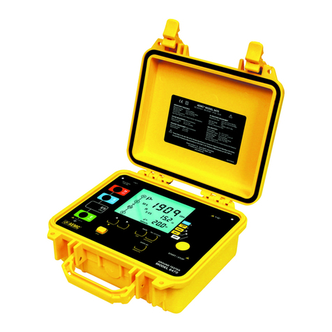
AEMC 6470-b User manual

DIGITAL GROUND RESISTANCE
AND SOIL RESISTIVITY TESTER
E N G L I S H User Manual
www. .com information@itm.com1.800.561.8187

www. .com information@itm.com1.800.561.8187

READ CAREFULLY BEFORE
USING FOR THE FIRST TIME
• Long battery charge life for a limited volume and weight.
• Possibility of quickly recharging your battery.
•
battery even if it is not fully discharged.
•
or cadmium, in compliance with the applicable regulations.
After prolonged storage, the battery may be completely discharged. If so, it must
be completely recharged.
Your instrument may not function during part of this recharging operation.
• Only use the charger supplied with your instrument. Use of
another charger may be dangerous.
• Only charge your instrument at temperatures between 0° and 40°C.
•
•
manual.
NiMH technology allows a limited number of charge/discharge cycles depending
• The conditions of use.
• The charging conditions.
Please refer to § 9 for correct replacement of the battery.
Do not dispose of the battery pack with other solid waste. Used batteries
specialized in processing hazardous materials.
www. .com information@itm.com1.800.561.8187

1.1 International Electrical Symbols ...........................................................7
.................................................7
.....................................................................7
1.4 Ordering Information ............................................................................7
1.4.1 Kits, Accessories and Replacement Parts ..............................8
2.1 Description ...........................................................................................9
2.2 Key Features......................................................................................10
2.3 Control Features ................................................................................11
2.4 Display ...............................................................................................12
2.5 Button Functions ................................................................................14
3.1 Reference Conditions.........................................................................15
3.2 Electrical.............................................................................................15
3.2.1 Frequency Measurements ....................................................15
3.2.2 Voltage Measurements .........................................................15
3.2.3 DC Resistance Measurements .............................................16
3.2.4 AC Earth/Ground Resistance Measurements.......................17
............................................18
3.3 Data Storage......................................................................................20
3.4 Power.................................................................................................20
3.5 Mechanical.........................................................................................21
....................................................................................21
3.7 Safety .................................................................................................21
4.1 General Operating Instructions ..........................................................22
4.1.1 Automatic Mode....................................................................22
4.1.2 Manual (Expert) Mode ..........................................................22
.........................................23
www. .com information@itm.com1.800.561.8187

5.1 Switching the Test Voltage .................................................................24
5.2 Resistance Measurement m ..............................................24
5.2.1 Lead Compensation Measurement ......................................25
5.2.2 Alarm Function......................................................................26
5.3 Resistance Measurement m ..............................................27
.................................................28
5.4.1 62% Method..........................................................................28
5.4.2 Full Method ...........................................................................30
5.4.3 Recommendations for a Reliable Measurement...................31
.................................................32
Position)........................................34
......34
5.6.2 Changing the Measurement Method.....................................35
5.6.3 Programming the Distance for Electrode Placement............35
....................................................................36
5.6.5 Schlumberger Method...........................................................37
6.1 Switching the Test Voltage .................................................................39
6.2 Measurement Frequency Selection ...................................................40
6.3 Manual Settings for m Measurements ............................................40
6.3.1 Continuity Test ......................................................................41
................................ 41
....................................41
6.4.2 Earth/Ground Coupling Measurements ................................41
.................................................43
...........................................................43
6.7 Smoothing..........................................................................................43
7.1 ...................................................44
7.2 Recalling Measurements from Memory .............................................45
7.3 Erasing Measurements from Memory ................................................45
7.3.1 Erasing All Measurements ....................................................45
.........................................45
8.1 Installing DataView®...........................................................................47
...............................49
www. .com information@itm.com1.800.561.8187

8.3 Establishing Communication to the Instrument..................................49
8.4 The Ground Tester Control Panel ......................................................50
.................................................................51
8.5.1 DC Continuity Test ..............................................................51
..........................................51
..................................................52
.........................................................52
8.6 Tools Menu.........................................................................................53
8.6.1 Tools > Options .....................................................................53
8.6.2 Tools > Colors .......................................................................53
...........................................................53
8.7 Starting a Test ....................................................................................53
8.8 Downloading Data to Database .........................................................53
8.8.1 Session Properties................................................................54
8.9 Exporting the Report to a PDF File ..................................................54
9.1 Maintenance.....................................................................................55
9.2 Cleaning...........................................................................................55
9.3 Fuse Replacement...........................................................................55
9.4 Recharging the Battery ....................................................................56
9.5 Replacing the Battery.......................................................................57
10.1 Error Reporting.................................................................................50
10.1.1 Electrode Resistance Too High.............................................59
10.1.2 Out of Range.........................................................................59
10.1.3 Misconnection ......................................................................59
10.1.4 Out of Limits Indicators .........................................................60
10.1.5 Error Messages.....................................................................61
Basic Terminologies ....................................................................................62
Glossary ......................................................................................................63
Repair and Calibration.................................................................................66
Technical and Sales Assistance ..................................................................66
.........................................................................................67
........................................................................................67
www. .com information@itm.com1.800.561.8187

Please read and comply
•
of protection of this equipment may be compromised if used in a manner
• Safety is the responsibility of the operator.
• All metal objects or wires connected to the electrical system should be
assumed to be lethal until tested. Grounding systems are no exception.
•
surement category.
•
• Do not use the instrument or its accessories if they appear damaged.
•
greater than or equal to those of the instrument (CAT IV 50V). Use only
•
• Check that no terminal is connected and the switch is set to OFF before
• Use only the charging unit supplied with the instrument to recharge the
battery.
•
•
to decide whether to continue or postpone measurements in these
situations.
www. .com information@itm.com1.800.561.8187

For measurements performed at the primary electrical supply (<1000V) such
For measurements performed on circuits directly connected to the electrical
distribution system. Examples are measurements on household appliances or
portable tools.
packing list. Notify your distributor of any missing items. If the equipment appears
container to substantiate your claim.
Ground Resistance Tester Model 6470-B.....................................Cat. #2135.01
Includes carrying bag, 110/240V power adapter with US power cord, optical USB cable,
rechargeable NiMH battery pack, and a USB stick with DataView® software, ground tester
workbook and user manual.
Ground Resistance Tester Model 6470-B Kit (150 ft) ..................Cat. #2135.02
Includes meter, two carrying bags, two 150 ft color-coded leads on spools (red/blue), one 30
ft lead (green), two 5 ft color-coded leads (red/blue), 110/240V power adapter with US power
one 100 ft tape measure, rechargeable NiMH battery pack, and a USB stick with DataView®
software, ground tester workbook and user manual.
www. .com information@itm.com1.800.561.8187

Ground Resistance Tester Model 6470-B Kit (300 ft) ..................Cat. #2135.03
Includes meter, two carrying bags, two 300 ft color-coded leads on spools (red/blue), two 100
ft color-coded leads (hand-tied, green/black), two 5 ft color-coded leads (red/blue), 110/240V
power adapter with US power cord, optical USB cable, four T-shaped auxiliary ground
pack, and a USB stick with DataView® software, ground tester workbook and user manual.
Ground Resistance Tester Model 6470-B Kit (500 ft) ..................Cat. #2135.04
Includes meter, two carrying bags, two 500 ft color-coded leads on spools (red/blue), two
100 ft color-coded leads (hand-tied, green/black), one 30 ft lead (green), two 5 ft color-
coded leads (red/blue), 110/240V power adapter with US power cord, optical USB cable,
rechargeable NiMH battery pack, and a USB stick with DataView® software, ground tester
workbook and user manual.
Test Kit for 3-Pole (3-Point) Testing (150 ft) .................................Cat. #2135.35
Includes one carrying bag, two 150 ft color-coded leads on spools (red/blue), one 30 ft lead
(green), two 5 ft color-coded leads (red/blue), two T-shaped auxiliary ground electrodes, set
Test Kit for 4-Pole (4-Point) Testing (300 ft) .................................Cat. #2135.36
Includes one carrying bag, two 300 ft color-coded leads on spools (red/blue), two 100 ft color-
coded leads (hand-tied, green/black), two 5 ft color-coded leads (red/blue), four T-shaped
Test Kit for 4-Pole (4-Point) Testing (500 ft) .................................Cat. #2135.37
Includes one carrying bag, two 500 ft color-coded leads on spools (red/blue), two 100 ft
color-coded leads (hand-tied, green/black), one 30 ft lead (green), two 5 ft color-coded leads
tape measure.
Test Kit for 3-Pole (3-Point) Testing
............................................. Cat. #2135.38
Includes one carrying bag, two 100 ft color-coded leads (hand-tied, green/black), one 30 ft
ft tape measure.
Extra Large Classic Tool Bag ........................................................... Cat. #2133.73
Tape Measure (100 ft) ...................................................................... Cat. #2130.60
................................................... Cat. #2130.64
Set of Two, 14.5" .................Cat. #2135.39
............................................. Cat. #2135.40
Optical USB Cable............................................................................Cat. #2135.41
DC to 120VAC ......................Cat. #2135.43
....................Cat. #2135.81
Rechargeable NiMH 9.6V Battery Pack ........................................... Cat. #2960.21
...Cat. #5000.13
Power Cord 115V US ....................................................................... Cat. #5000.14
www. .com information@itm.com1.800.561.8187
measures from 0.01 to 99.99k
optimum measurement range and test current.
the results. Up to 512 test results can be stored in internal memory for later recall
® software.
status and more.
than 250VAC
250VAC.
against dust and water when closed (the test button is also sealed against the
elements); manual and automatic test frequency selection from 40 to 513Hz; user
optional 12V battery adapter.
maintenance crews performing numerous tests. It exceeds mechanical and safety
accuracy.
www. .com information@itm.com1.800.561.8187

•
•
frequency selection
•
measurements with manual and automatic frequency selection and automatic
lead compensation.
•
Rho (
•
• Manual and automatic frequency scan from 40 to 513Hz for optimum test ac
•
•
•
• Stores up to 512 complete test results in internal memory
• Optically isolated USB communication
• Remote set up and operation of all measurements using DataView® software
supplied
• Automatic report generation
•
•
• Grounding standards IEC 61557 parts 4 and 5 compliant
• Includes DataView®
www. .com information@itm.com1.800.561.8187
Figure 2-1
www. .com information@itm.com1.800.561.8187
The backlight turns ON automatically when entering a function and
turns OFF after the function is complete. Press the DISPLAY button to turn it back
on.
Figure 2-2
www. .com information@itm.com1.800.561.8187
www. .com information@itm.com1.800.561.8187
www. .com information@itm.com1.800.561.8187

-
tions and the operating error under the operating conditions in accordance with
IEC 61557 (1.4 and 5).
Digital with a sampling frequency of 4028Hz, low pass, FFT.
The frequency of the strongest spectral component is displayed.
Display updates approx. 3 times per s.
between 70 and 75V at terminals H (Z) and E (X)
If terminals H (Z) and E (X)
fuse will blow.
www. .com information@itm.com1.800.561.8187
External Voltage Measurements
The frequency of the strongest spectral component is displayed.
Display updates approx. 3 times per s.
Voltage/Current measurement (Standard EN 61557 part 4)
16VDC (if resistance < 22
reduced to 10VDC)
> 200mADC for resistances < 20
50Vrms (protection up to 250V is guaranteed)
2 H
60Vpeak > 10Hz
approx 5 s
3 per s in manual mode
Possible from 0 to 5
“>” or “<” from 1 to 999 (max 3 digits)
2-Pole m measurement
www. .com information@itm.com1.800.561.8187
4-Pole m measurement
Voltage/Current measurement (EN 61557 part 5)
Selectable from 41 to 513Hz (see table in § 6.2)
> 200mAAC
test frequency
250Vrms
Max. Value for RH & RS100k
E at
128Hz, then 3 measurements per s.
E at
128Hz, then 3 measurements per s.
32V, test frequency of 128Hz, RH and RS = 1k
The operating error of AC resistance measurements can be less than that speci
are matched to those of the current channel.
Measurement of auxiliary electrodes RH, RS, RES, RE
The START button must be pressed for more than 2 s. For frequencies between
41 and 256Hz, the resistance of the auxiliary earth electrodes is measured at the
test frequency set. At higher frequencies the resistance is measured at 256Hz.
www. .com information@itm.com1.800.561.8187
3-Pole earth resistance measurement RE
OUT H.
4-Pole earth resistance measurement RE
OUT H.
Voltage/Current measurement (EN 61557 part 5)
Selectable from 41 to 128Hz (see table in § 6.2)
> 200mAAC
test frequency
250Vrms
www. .com information@itm.com1.800.561.8187
Max.Value for RH, RS, RES, RE100k
= 2 d R
S = (
Maximum Value of 999k m (display in k ft is not possible)
at
128 Hz, then 3 measurements per s.
at
128 Hz, then 3 measurements per s.
32V, test frequency of 128Hz, R , R , R and R = 1k
Rrod is the resistance of the earth rods R , R , R , R assumed to be identi
cal.
OUT rod.
Measurement of Auxiliary Electrodes R H, R S, R ES, R E
The START button must be pressed for more than 2s. For frequencies between 41
and 128Hz, the resistance of the auxiliary earth electrodes is measured at the test
frequency set. At higher frequencies the resistance is measured at 128Hz.
www. .com information@itm.com1.800.561.8187
Other manuals for 6470-b
1
This manual suits for next models
3
Other AEMC Test Equipment manuals