Steriline RA-V4 User manual

ROTARY WASHING
MACHINE
MECHANICAL &
MAINTENANCE
MANUAL
MACHINE TYPE: ROTARY WASHING MACHINE
MACHINE MODEL: RA-V4
SERIAL NO. 15499LV
YEAR: 2016
CUSTOMER: Intarcia - USA -
STERILINE S.R.L.Via Tentorio 30, 22100 -COMO- ITALY
Ph. +39.031592064


ROTARY WASHING MACHINE
MECHANICAL &MAINTENANCE MANUAL
RA-V4 1.0 (23.01.2017)
15499LVMA01-1 -
MECHANICAL MAINTENANCE
MANUAL
Pg.3
Index
1
PERFORMANCES..................................................................................................7
2
INSTALLATION......................................................................................................8
2.1
INSPECTION AT RECEIPT ................................................................8
2.1.1 Technical data ............................................................................................................8
2.1.2 Dimensions .................................................................................................................8
2.2
INTERNAL TRANSPORT...................................................................9
2.2.1 Crated machine ........................................................................................................10
2.2.2 Uncrated machine.....................................................................................................10
2.3
REMOVE PACKAGING ................................................................... 11
2.3.1 Pallet.........................................................................................................................11
2.3.2 Box or crate ..............................................................................................................11
2.4
STORAGE ................................................................................. 12
2.4.1 Environment..............................................................................................................12
2.4.2 Loads ........................................................................................................................12
2.4.3 Change Parts............................................................................................................12
2.5
POSITIONING ............................................................................. 13
2.6
CONNECTIONS ........................................................................... 14
2.6.1 Utilities Connections .................................................................................................14
2.6.2 Electrical connection.................................................................................................14
2.7
STEP CONTROL ......................................................................... 15
2.8
START UP................................................................................. 15
3
ROTARY WASHING MACHINE MODEL RA-V4 .................................................16
3.1
WASHER DESCRIPTION ................................................................ 16
3.2
WASHING CYCLE ........................................................................ 17
3.2.1 Pre-flushing...............................................................................................................18
3.3
WASHING STATIONS .................................................................... 18
3.3.1 Compressed air station.............................................................................................18
3.3.2 WFI station................................................................................................................18
3.4
PROTECTION HOOD..................................................................... 19
3.4.1 Draining ....................................................................................................................19
3.4.2 Drying .......................................................................................................................19
4
FORMAT CHANGE ..............................................................................................20
4.1
FORMAT CHANGE PARTS .............................................................. 21
4.1.1 Infeed guides ............................................................................................................22
4.1.2 Loading cylinder contrast..........................................................................................23
4.1.3 Loading cylinder guide..............................................................................................24
4.1.4 Loading position guide..............................................................................................25
4.1.5 Pincers jaws..............................................................................................................26
4.1.6 Unloading station guides ..........................................................................................27
4.1.7 Outfeed guides .........................................................................................................28
4.1.8 Needles.....................................................................................................................29
4.2
ADJUSTABLE PARTS .................................................................... 30
4.2.1 Infeed minimum load ................................................................................................31
4.2.2 Inlet lifting side guide cylinder...................................................................................32

ROTARY WASHING MACHINE
MECHANICAL &MAINTENANCE MANUAL
Pg.4
15499LVMA01-1 -
mechanical maintenance
manual
1.0 (23.01.2017) RA-V4
4.2.3 External water spraying nozzles station 3 ................................................................33
4.2.4 External air blowing nozzles station 7 ......................................................................34
4.2.5 Tower/Needles Height..............................................................................................35
5
GENERAL INSTRUCTION ...................................................................................36
5.1
USE OF DETERGENTS HAZARDOUS TO HEALTH ...................................36
5.2
CLEANING PRIOR TO START-UP ......................................................36
5.3
SIZE CHANGE PARTS CLEANING......................................................37
5.4
GENERAL..................................................................................38
5.5
DISPOSAL .................................................................................39
5.5.1 Batteries ...................................................................................................................39
5.5.2 Lubricants.................................................................................................................39
5.6
INSTRUCTIONS FOR USE OF LUBRICANTS..........................................40
5.6.1 Contact with skin ......................................................................................................40
5.6.2 Disposal....................................................................................................................40
5.7
VALVES ASSEMBLING -SMC VALVES ..............................................41
5.8
GENERAL LUBRICATION INSTRUCTIONS............................................42
6
RECOMMENDED LUBRICANTS .........................................................................43
6.1
IN GENERAL...............................................................................43
6.2
INSTALLED AGGREGATES OF OTHER MANUFACTURERS........................43
6.3
LUBRICATING STUFF LIST .............................................................44
6.3.1 Oil Lubrication ..........................................................................................................44
6.3.2 Grease Lubrication ...................................................................................................44
7
INSPECTION ........................................................................................................45
7.1
INSPECTION SCHEDULE ................................................................45
7.2
INSPECTION PLAN.......................................................................45
7.2.1 Pneumatic cylinder ...................................................................................................47
7.2.2 Pneumatic valves .....................................................................................................48
7.2.3 Gear .........................................................................................................................49
7.2.4 Chain ........................................................................................................................50
7.2.5 Chain wheel..............................................................................................................51
7.2.6 Chain joint ................................................................................................................52
7.2.7 Ball bearing ..............................................................................................................53
7.2.8 Pillow block...............................................................................................................54
7.2.9 Motors ......................................................................................................................55
7.2.10 Conveyor belt ...........................................................................................................56
7.2.11 EMERGENCY STOP Device....................................................................................57
8
MAINTENANCE....................................................................................................58
8.1
MAINTENANCE INTERVAL ..............................................................58
8.1.1 Daily .........................................................................................................................58
8.1.2 Weekly......................................................................................................................59
8.1.3 Monthly.....................................................................................................................60
8.1.4 Quarterly...................................................................................................................61
8.1.5 Half-yearly ................................................................................................................62
8.1.6 Other Maintenance Hints..........................................................................................63
9
SPARE PARTS.....................................................................................................65
9.1
COMMERCIAL COMPONENTS SPARE PARTS ......................................65

ROTARY WASHING MACHINE
MECHANICAL &MAINTENANCE MANUAL
RA-V4 1.0 (23.01.2017)
15499LVMA01-1 -
mechanical maintenance
manual
Pg.5
9.2
MECHANICAL COMPONENTS SPARE PARTS....................................... 65
9.2.1 Infeed guide ..............................................................................................................66
9.2.2 Loading cylinder contrast..........................................................................................67
9.2.3 Loading cylinder guide..............................................................................................68
9.2.4 Loading position guide..............................................................................................69
9.2.5 Pincers......................................................................................................................70
9.2.6 Unloading station guides ..........................................................................................71
9.2.7 Outfeed guides .........................................................................................................72
9.2.8 Washing station ........................................................................................................73
9.2.8.1 Needles distributor.............................................................................................................73
9.2.8.2 Needles .............................................................................................................................74
9.2.8.3 External nozzles ................................................................................................................75
9.2.9 Drying station............................................................................................................76
9.3
INDICATION FOR ORDER............................................................... 77
10
ATTACHMENTS...................................................................................................78


ROTARY WASHING MACHINE
MECHANICAL &MAINTENANCE MANUAL
RA-V4 1.0 (23.01.2017)
15499LVMA01-1 -
mechanical maintenance
manual
Pg.7
1 PERFORMANCES
The Rotary Washing Machine model RA-V4 is designed to handle glass vials having the following
dimensions:
Container type Diameter
[mm]
Height
[mm]
Output
[v/h]
Format Mark
15ml
26,75
57,00
1500
F0
The washer has pincers to treat vials.
The number of pincers is 8 and the number of vials per pincers is 3.
The processing parameters for each washing cycle are included in the recipes parameters setting.

ROTARY WASHING MACHINE
MECHANICAL &MAINTENANCE MANUAL
Pg.8
15499LVMA01-1 -
mechanical maintenance
manual
1.0 (23.01.2017) RA-V4
2 INSTALLATION
2.1 INSPECTION AT RECEIPT
Inspect the machine immediately after unloading. All damages and contamination, caused during
transport, must be reported to the forwarding company, and must be stated in the forwarding
papers as well.
In case of shipment in a wooden box, all damages to the box must also be stated in the forwarding
papers.
IMPORTANT
All damages should be reported to Steriline S.r.l. within 5 working
days after receipt.
Describe damages as accurately as possible.
By means of the forwarding documents, check the presence of all parts. In the event that anything
is missing, report this to Steriline S.r.l. within 5 working days after receipt.
2.1.1 Technical data
Also see Control System Manual (Ref. 15499QE3MA01).
2.1.2 Dimensions
Length
mm
1656
Width
mm
976
Height
mm
2203
Production level
mm
900±25
Weight approx.
Kg
600
(See Layout Ref. 15499LVLY01)

ROTARY WASHING MACHINE
MECHANICAL &MAINTENANCE MANUAL
RA-V4 1.0 (23.01.2017)
15499LVMA01-1 -
mechanical maintenance
manual
Pg.9
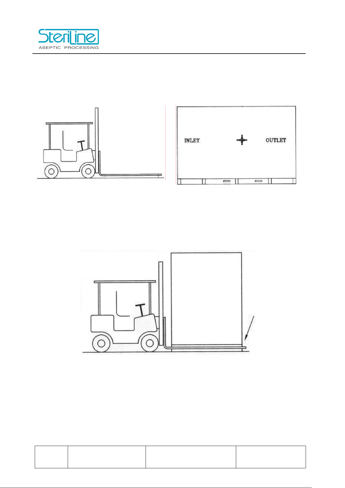
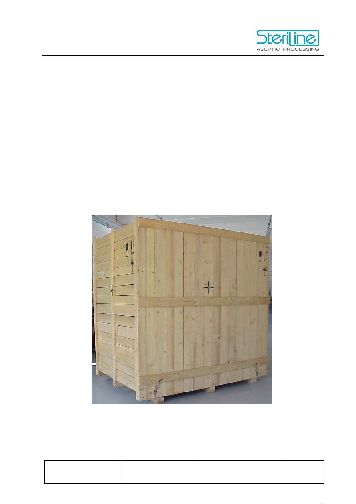
2.2 INTERNAL TRANSPORT
Internal transport is best left to a specialized company for internal machine transport.
Read carefully the instructions and the signs on the equipment shipping box/crate.
(NOTE: Do not expose the equipment to significant shocks or vibrations.)
CENTER OF
BALANCE
FRAGILE
KEEP DRY
OFF BALANCE
SLING HERE
THIS END UP
DO NOT USE HOOK
ROTARY WASHING MACHINE
MECHANICAL &MAINTENANCE MANUAL
Pg.10
15499LVMA01-1 -
mechanical maintenance
manual
1.0 (23.01.2017) RA-V4
2.2.1 Crated machine
Using a fork lift, raise the box/crate and slide it on the forks until it stops against the lift’s vertical
guide for stability; and then transport the equipment on an even floor without any pits or holes.
2.2.2 Uncrated machine
Using a fork lift, raise the machine as little as possible and tilt the forklift beam to support the
machine against it. Secure the machine against the forklift beam by means of a safety strap for
safe transport.
ROTARY WASHING MACHINE
MECHANICAL &MAINTENANCE MANUAL
RA-V4 1.0 (23.01.2017)
15499LVMA01-1 -
mechanical maintenance
manual
Pg.11
2.3 REMOVE PACKAGING
2.3.1 Pallet
Keep the machine attached to its shipping pallet until it is placed at its final location. Before
removing the pallet, locate the machine as close as possible to its final location; then lift the
machine from the pallet using a fork-lift truck as described in section 2.3.2.
2.3.2 Box or crate
Keep the box or crate closed during storage to avoid damage or loss of enclosed machine parts.
Remove the box/crate only after it has been placed at its final location. Using a crowbar, remove
the box panels that are nailed in place. Use a 10 mm wrench to remove the box panels that are
bolted together. After uncrating the equipment, compare the actual contents of the box with the
packing list or forwarding documents.

ROTARY WASHING MACHINE
MECHANICAL &MAINTENANCE MANUAL
Pg.12
15499LVMA01-1 -
mechanical maintenance
manual
1.0 (23.01.2017) RA-V4
2.4 STORAGE
2.4.1 Environment
Machines, shipped on a pallet or crate, should be stored in a dry (relative humidity maximum
80%) and dust-free place, free of condensation of which the minimum temperature will never get
below 10°C to avoid condense in e.g. control cabinets; the maximum temperature may not exceed
40°C. The storage room should also be free of vermin.
Machines, shipped in seaworthy packaging, should be stored in a dry (unheated) place since
protection against condense was provided during packaging.
When machines must be kept in store unexpectedly for a longer period of time, consult Steriline
s.r.l. for specific measures.
2.4.2 Loads
Packed equipment may not be stacked. Take notice of the signs on the packing.
2.4.3 Change Parts
Store in a dry (relative humidity maximum 80%) and dust-free environment, free of condensation;
maximum temperature 40°C. The storage room should also be free of vermin.
Store a complete set of change parts according to machine number and vial type.
ROTARY WASHING MACHINE
MECHANICAL &MAINTENANCE MANUAL
RA-V4 1.0 (23.01.2017)
15499LVMA01-1 -
mechanical maintenance
manual
Pg.13
2.5 POSITIONING
For exact location of the utilities and machine dimension refer to the layout drawing
(15499LVLY01).
Before installing the machine, ensure that the following actions have been carried out:
- unpack the machine and all the separately packed components
- make the floor free of all objects in the area where the machine must be placed
- clean the floor
- check if every necessary utility is available.
Adjust the height of the machine by rotating the shafts of the feet. By means of a spirit level on
the frame, check that the machine is in plane.
Important Verify that each feet supports the frame of the machine!
Important
Verify by means of a spirit level that the mac
hine is
positioned horizontally!
ROTARY WASHING MACHINE
MECHANICAL &MAINTENANCE MANUAL
Pg.14
15499LVMA01-1 -
mechanical maintenance
manual
1.0 (23.01.2017) RA-V4
2.6 CONNECTIONS
2.6.1 Utilities Connections
In the positions indicated in the Layout Drawing (Rif. 15499LVLY01), the following utilities have
to be connected:
W.F.I.
Pipe ∅
in
¾ Tri Clamp
COMPRESSED AIR
Pipe ∅
in
¾ Tri Clamp
WATER DRAIN
Water process drain ∅
in
1 Tri Clamp
EXHAUST AIR
Duct external size
mm
140x140
2.6.2 Electrical connection
The electric connection is made between the electrical cabinet and the electrical box on the side
of the machine.
For detailed information refer to the Control System Manual 15499QE3MA01.

ROTARY WASHING MACHINE
MECHANICAL &MAINTENANCE MANUAL
RA-V4 1.0 (23.01.2017)
15499LVMA01-1 -
mechanical maintenance
manual
Pg.15
2.7 STEP CONTROL
Preset the washing machine to the vial type to perform and select set-up mode on the HMI
(Human Machine Interface). Insert the jog button in the relative socket on the control panel.
Feed the glassware on the rotating table and by operating the machine with the jog button, control
the following items:
•When the inlet pincer is in position and opened, the infeed belt starts to load the glassware
on the inlet pincer.
•The pincer closes and the washer starts.
•There are eight stations and the washer drive is based on an intermittent motion. Each
station takes up three glassware per index. The pincers close around the body of the
glassware. Glassware is transported to the different washing stations by the pincers.
•While the washer is moving, the glassware passes through the washing and drying
stations in an upside and down position.
•The injection of compressed air, W.F.I. into the glassware is carried out when the needles
are in the raised position.
•After washing, the glassware is up-righted and directly discharged onto the
depyrogenation tunnel conveyor belt by a pneumatic cylinder.
•The vials pass through the tunnel inlet chamber then enter the sterilizing chamber, where
the depyrogenating process takes place.
•The vials never stop moving and then enter the cooling chamber to cool down to a suitable
temperature before discharge.
•All the safeties operate correctly.
2.8 START UP
Before starting the first setting up of the machine, control the following items:
•all the utilities are correctly connected and the fluids pressures are correctly set
•the filters are correctly installed
•run the machine with the washing cycle operating

ROTARY WASHING MACHINE
MECHANICAL &MAINTENANCE MANUAL
Pg.16
15499LVMA01-1 -
mechanical maintenance
manual
1.0 (23.01.2017) RA-V4
3 ROTARY WASHING MACHINE MODEL RA-V4
The RA-V4 washing machine is designed to perform the chemical, particulate and bacteriological
cleaning of glass vials by means of series of injections of water for injection (W.F.I.) and
compressed air (C.A.) on the internal and external surfaces of the vials.
The tags numbers listed in the below sections refer to the P&ID (Piping and Instruments Diagram)
document no.15499LVPI01.
3.1 WASHER DESCRIPTION
When the automatic start cycle has been started and the green button on the operator panel
blinks, the operator loads the vials on the motorized rotating table M20.
The rotating table transports the glassware toward the motorized infeed belt M1 which brings the
glassware to the loading system. The sensor ZS02 stops the machine in case of minimum load
on the rotating table.
The vials loading cylinder ZA15 (KJ15B and KJ15F actuated) guides the glassware toward the
pincer. The inlet side guide cylinder ZA9(KJ09B and KJ09F actuated) lifts the inlet side guide to
keep the glassware in position avoiding that glassware falls down.
The pincers are opened and load the glassware. If during these operations the synchronism of
the vials loading cylinder, the inlet side guide and the pincers with the glassware is wrong, the
safety sensors ZS15B (Vials loading cylinder backward sensor) or ZS09B (Inlet lifting side guide
cylinder backward sensor) stops the machine with alarm. The glassware are load in the pincers
in row of 3 vials.
The glassware are rotating by the movement of the pincers. The vials are turned upside down
and proceed into the washing and drying stations.
After the glassware is loaded, the washer is moved in a stepwise motion by the M3 main servo
drive motor. The main servo drive motor stops when a maximum torque condition takes place and
stops the machine with alarm.
During the washing the glassware is positioned by the pincers over the internal spraying needles
and under the external blowing nozzles. The movement of the pincers is controlled by these
cylinders:
-ZA1 (KJ01O/C open/close actuated and KJ01L/R left/right actuated),
-ZA2(KJ02O/C open/close actuated and KJ02L/R left/right actuated),
-ZA3(KJ03O/C open/close actuated and KJ03L/R left/right actuated),
-ZA4(KJ04O/C open/close actuated and KJ04L/R left/right actuated),
-ZA5(KJ05O/C open/close actuated and KJ05L/R left/right actuated),
-ZA6(KJ06O/C open/close actuated and KJ06L/R left/right actuated),
-ZA7(KJ07O/C open/close actuated and KJ07L/R left/right actuated),
-ZA8(KJ08O/C open/close actuated and KJ08L/R left/right actuated).
When the glassware is in position the needles are lifted by the ZA14 cylinder (KJ14B and KJ14F
actuated), penetrate the glassware and spray the fluids for the set time. If there is something
wrong with the movement of the lifting cylinder, it is detected by the ZS14B sensor, an alarm is
activated and the machine stops.

ROTARY WASHING MACHINE
MECHANICAL &MAINTENANCE MANUAL
RA-V4 1.0 (23.01.2017)
15499LVMA01-1 -
mechanical maintenance
manual
Pg.17
During the operation, while the control valves are open, the PLC checks the pressure of fluids
before the needles. If the pressure is below the limit the machine stops with alarm. Once the
operator has removed the cause, the operation may continue.
(See also Operation Manual)
During the washing process, if the operator opens a washer door the machine stops with alarm
by means of the proximity switch ZS10A and ZS10B.
The process parameters are defined for all of the glassware formats foreseen in the contract.
They are saved in the PLC recipes and listed in the “Recipes parameters setting” tables
(Ref.15499QE3SP27 attached to the Operation manual).
After washing and drying, the glassware are up-righted and directly discharged onto the tunnel
conveyor belt.
The glassware keeps its position by means of the exit lifting side guide, which is moved by cylinder
ZA11 (KJ09B and KJ09F actuated) and the vials unloading cylinder ZA12 (KJ12B and KJ12F
actuated) helps the discharge of the glassware to the tunnel conveyor belt.
If there is an obstruction in the cylinders motion, the safety sensors ZS11B (Outfeed lifting side
guide cylinder backward sensor) and ZS12B/F (Vials unloading cylinder backward/forward
sensors) stop the machine with alarm.
3.2 WASHING CYCLE
In the next chapters the process fluids will be abbreviated as follow:
- C.A. (Compressed Air)
- W.F.I. (Water for Injection)
The washing cycle is designed as following:
Station 1:
Loading of glassware on the pincers
Station 2:
Injection of W.F.I.
Station 3:
Injection of C.A. / Spraying of W.F.I. over the vials
Station 4:
Injection of W.F.I.
Station 5:
Injection of C.A.
Station 6:
Injection of W.F.I.
Station 7:
Injection of C.A. / Blowing of C.A. over the vials
Station 8:
Unloading of vials from the pincers

ROTARY WASHING MACHINE
MECHANICAL &MAINTENANCE MANUAL
Pg.18
15499LVMA01-1 -
mechanical maintenance
manual
1.0 (23.01.2017) RA-V4
3.2.1 Pre-flushing
The washer pre-flushing consists of water spraying in the fluids piping lasting a set time. This
function automatically starts when the production starts and after a machine stop. When the
machine stops, a countdown set time begins. If the countdown ends, the pre-flushing is
automatically activated when the user re-starts the machine.
3.3 WASHING STATIONS
The vials are washed by special needles, which are designed to prevent clog during operation
and not stagnant water, to be dismantled, easily installed and ready for maintenance.
3.3.1 Compressed air station
Dry (oil free) compressed air is used to dry the glassware. The blowing time is a settable data and
can vary according to the vials size.
The Compressed Air station consists of a pipeline on which are fitted:
-Process C.A. pressure reducer PJ40 with manometer PI40
-4” hydrophobic OPTICAP capsule 0.22 micron filtration capacity DF40
-Membrane valve for the internal air blowing control KV40 (KJ40 actuated)
-Pressure transmitter for internal air flow control PT40
-Membrane valve for the external air blowing control KV41 (KJ41 actuated)
-Service C.A. pressure reducer PJ42 with manometer PI42
-Service compressed air switch PSL42
-Pressure reducer for open/close pincers actuators PJ43 with manometer PI43
-Pressure reducer for left/right pincers actuators PJ44 with manometer PI44
Pipe fittings are tri-clamp type.
3.3.2 WFI station
New water is used in the rinsing/washing steps: this water is collected in basins under the needles
and sent to the drain. The spraying time is a settable data and can vary according to the vials
size.
The WFI station consists of a pipeline on which are fitted:
-Pneumatic membrane valve for internal water spraying control KV50 (KJ50 actuated)
-Pressure transmitter for internal water spraying flow control PT55
-Pneumatic membrane valve KVA50 (KJA50 actuated) for drying the pipes
-W.F.I. manual sampling valve KVD50
Pipe fittings are tri-clamp type and designed respecting the 3D rule.

ROTARY WASHING MACHINE
MECHANICAL &MAINTENANCE MANUAL
RA-V4 1.0 (23.01.2017)
15499LVMA01-1 -
mechanical maintenance
manual
Pg.19
3.4 PROTECTION HOOD
The washer protection hood, made of transparent polycarbonate, separates the wet process area
of the machine from the environment.
At the washer outfeed the hood is connected to the Depyrogenating tunnel. The transfer line is
completely encased and protected by the air backflow from the tunnel.
On the doors, safety switches (ZS10A and ZS10B) are installed to stop the machine in case of
door/cover opening.
Over the room ceiling the exhaust fan V1 with motor MV1 are installed in order to exhaust the
vapors during operation.
On the washer a duct connection is foreseen. A low basin is installed on the machine to avoid
that the condensed water coming from the duct flows back into the process area.
3.4.1 Draining
To avoid water to remain for a long time in the idle machine, the draining is carried out at the end
of the production. Membrane valves are installed on the RW pipelines to empty them (refer above
to valves listed as KVDnn. The valves are automatically actuated (KJDnn).
3.4.2 Drying
Membrane valves feed compressed sterile air into the RW and WFI pipelines in order to dry them
(refer above to valves listed as KVAnn. The valves are automatically actuated (KJAnn).
ROTARY WASHING MACHINE
MECHANICAL &MAINTENANCE MANUAL
Pg.20
15499LVMA01-1 -
mechanical maintenance
manual
1.0 (23.01.2017) RA-V4
4 FORMAT CHANGE
The washing machine is set to operate the following vials:
GLASSWARE
Container type Format Mark
15ml F0
Important
NO FORMAT CHANGE PARTS ARE FORESEEN
FOR THIS MACHINE.
Important
In case of future implementation of different vial sizes, the
Format Change Parts listed in chapter 4.1 must be
equipped and the Washer Adjustable Parts listed in
chapter 4.2 must be regulated accordingly.
Table of contents


