Steris 4085 User manual
STERIS 4085 GENERAL SURGICAL TABLE
SD909 (02/01/16)
Item ________________________
Location(s)___________________
____________________________
WARNING
AVERTISSEMENT
CHARGEBATTERY
INTELLIPOWER
WARNING
AVERTISSEMENT
W0109-2000-SW
FDLKM-C.MAX
Ensurecapscover
socketswhennotinuse.
SERVE
C-MAX 38
The Selections Checked Below Apply To This Equipment
ACCESSORY PACKAGES
❑Standard Accessory Package
OPTIONS
❑Foot Control
APPLICATION
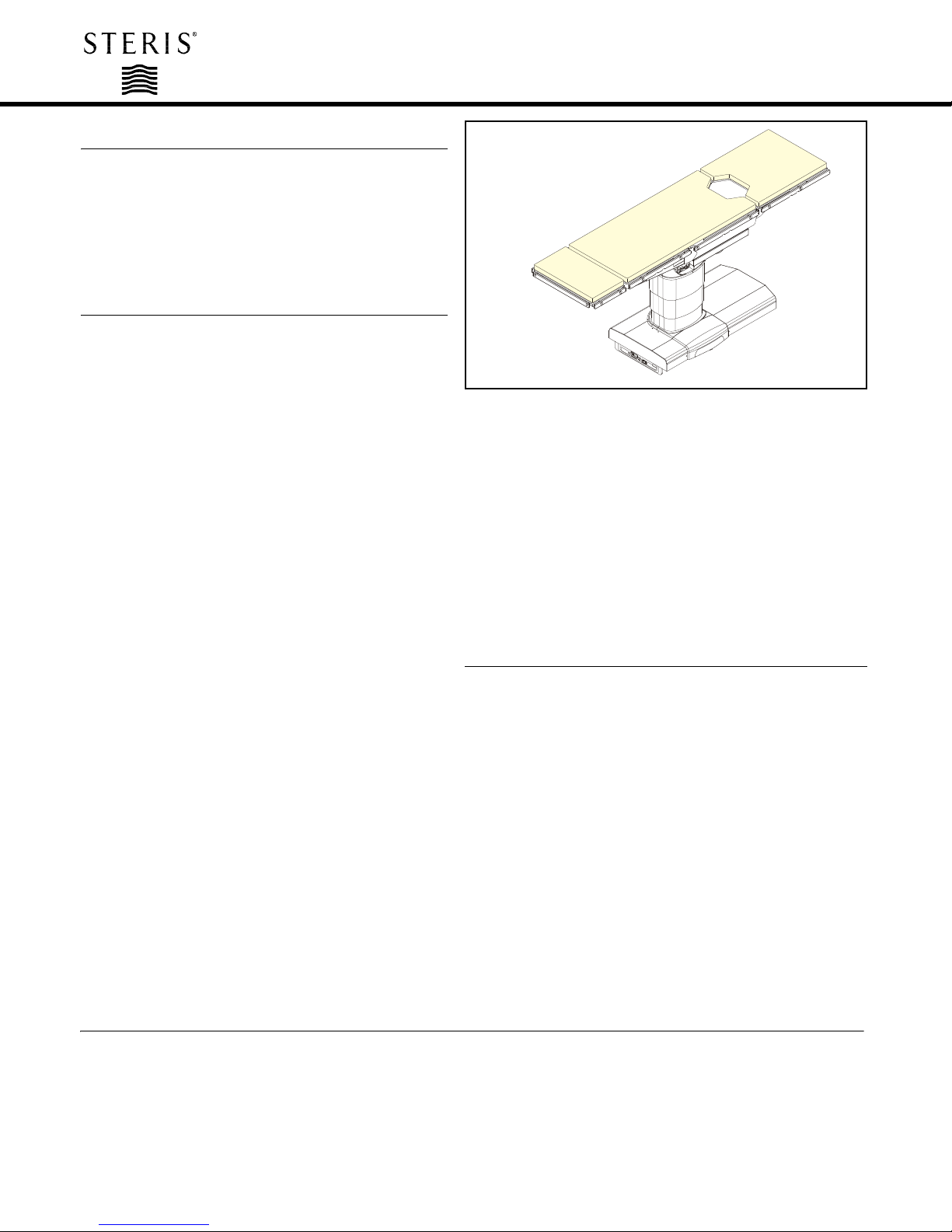
The STERIS 4085 General Surgical Table is a mobile,
electrohydraulically operated surgical table designed to
support virtually all general surgical procedures including
cardiac and vascular, endoscopic, gynecology, urology,
nephrectomy, neurology, ophthalmologic and orthopedics
with the addition of STERIS table accessories.
DESCRIPTION
The STERIS 4085 General Surgical Table is a mobile,
electrohydraulically operated surgical table specifically
designed to provide patient positioning flexibility required
for modern surgical care facilities. The STERIS 4085 General
Surgical Table features powered lateral tilt, Trendelenburg/
reverse Trendelenburg, Zip-Slide™ movable tabletop and
adjustable height functions. This table is designed to
function with:
•1100 lb (499 kg) load; without patient positioning (no
tabletop articulation or slide).
•1000 lb (454 kg) load; includes all patient positioning
except tabletop slide.
•600 lb (272 kg) load; includes all patient positioning
and full tabletop slide.
Table is constructed of aluminum alloy, stainless steel and
other high quality materials. Table is equipped with a large
sliding tabletop providing unrestricted radiological access
without patient reversing.
The STERIS 4085 General Surgical Table is powered by
either internal battery or facility electric through use of the
INTELLIPOWER®dual power system.
The table accepts positioning commands from three
sources:
1. A Primary Hand Control.
2. Physician-controlled foot control (which includes
Trendelenburg Tilts, Lateral Tilts, and Height functions).
3. Backup Hand Control functions as override to primary
Hand Control. Located in table base.
Overall size (W x L x H):
22 x 81 x 26 to 45" (547 x 2057 x 660 to 1143 mm).
Weight:
560 lb (254 kg).
The standard table configuration includes:
• Power adjustable height, back, leg, Trendelenburg, Zip-Slide
movable tabletop, radiolucent Kidney™ elevator mechanism,
flex/reflex and lateral tilt functions.
• Manual, removable, adjustable head section.
• Pendant primary Hand Control.
• Mobile base with hydraulically operated, self-leveling floor
locks
• Up to three weeks operation (100-150 procedures) on internal
battery power without recharging.
STANDARDS
STERIS 4085 tables are in compliance with the following
standards:
•Underwriters Laboratories (UL) Standard 60601-1 –
2nd Edition, as certified by ETL.
•Standard CSA-C22.2 No. 601.1-M90, Standard for Electro-
Medical Equipment, as certified by ETL.
•EN 60601-1: 1993, 2nd Edition, 1995, Electrical Safety, as
certified by ETL.
•IEC 601-1-2: 2001, Electromagnetic Compatibility, as
certified by ETL.
•EN 55011: Group I, Class A, Emissions Testing, as certified
by ETL.
•EN60601-2-46 – 1st Edition, as certified by ETL.
•CE Marked to Medical Device Directive, 93/42/EEC.
(Typical only - some details may vary.)
2
WARNING
AVERTISSEMENT
CHARGEBATTERY
INTELLIPOWER
WARNING
AVERTISSEMENT
W0109-2000-SW
FDLKM-C.MAX
Ensurecapscover
socketswhennotinuse.
SERVE
1
2
3
5
6
4
8
14
12
7
03"
00"
20¡ T
00¡
TRENDTILT
00¡
SLIDE HEAD!
-04¡
13
10
11
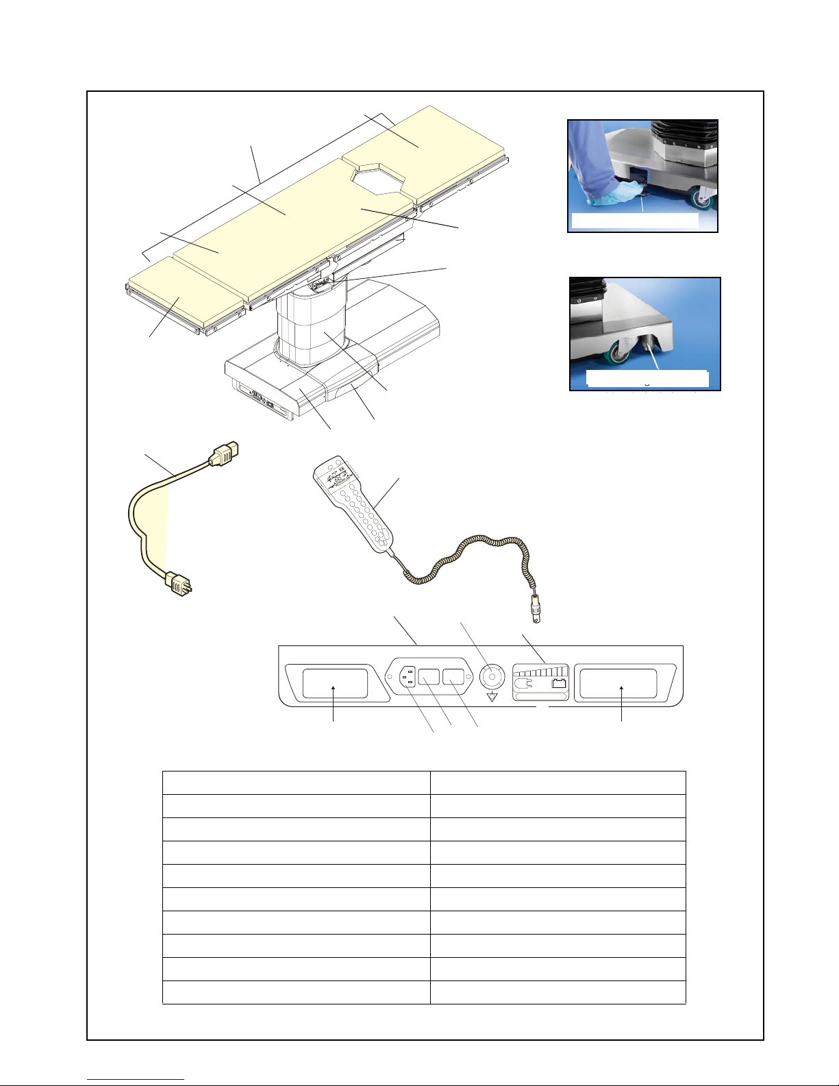
FIG. 4.1.2 - DESCRIPTION
915
CHARGE BATTERY
INTELLI POWER
16
17
KEY:
1 Table Base 11 INTELLIPOWER Display
2 Column 12 Connection Panel
3 Tabletop (See Page 3) 13 Hand Control (See Page 4)
4 Head Section 14 Auxiliary Control System (See Page 5)
5 Back Section 15 Ground Equalization Terminal (Male Connection)
6 Kidney Elevator Mechanism 16 Service Label
7 Seat Section (Sliding) 17 ServiceBar Code Label
8 Leg section 18 Primary Fuses
9 Power Panel 19 Main Power Switch
10 Power Cord 20 AC Receptacle
STERIS 4085 General Surgical Table Components (Typical)
20 19 18
Dimensions are typical -
drawing is not to scale.
11
Backup Foot Pump Pedal
Self Leveling Floor Lock
Self Leveling Floor Lock
3
•Title 21 - FDA, Part 820 - Quality System Regulation.
•Class 1 Equipment.
•Type B Equipment.
•IPX-4 (Fluid Ingress Protection), as certified by ETL.
NOTE: Suitable for intermittent operation, three minutes per
hour.
FEATURES
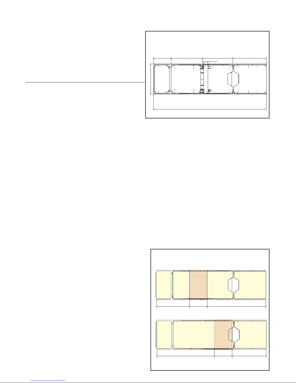
Motorizedtabletop
is constructed of five-sections (including the
motorized fully radiolucent Kidney Elevator Mechanism) and is
81" (2057 mm) long. Motorized Zip-Slide movable tabletop
eliminates the need for patient reorientation and preconfiguration
of the table. Unobstructed imaging length of 68" (1725 mm) and
100% C-Arm access without table movement is available. For
attaching accessories, the tabletop sections include a standard
stainless-steel side rail on both sides – located where they will
not obstruct the imaging area. Hook-and-loop fastener strips on
the tabletop sections permit instant application and removal of
the 2" (51 mm) thick, latex-free mattress pad. The radiolucent
tabletop sections enable viewing of the entire anatomy (see
illustration at bottom of this page). The easily attached X-Ray top
design enables cassettes to be loaded from the head, foot or
either side for a full range of exposure angles.
Columnsupports tabletop and includes lift cylinder, bearings,
hydraulic piping, hydraulic actuators for Trendelenburg,
electrical wiring and master computer. These components are
enclosed by four telescoping plastic or optional stainless-steel
column shrouds. The shrouds are of two-piece construction for
service accessibility. Hand Control and optional Foot Control
connect at top of column.
Base structure is painted welded steel. The base cover is a
two-section, plastic or optional stainless-steel enclosure. Four
large diameter swivel casters inside the base cover facilitate
table relocation and movement. Four mechanical, hydraulically
operated, floor-locks are supplied. The power supply assembly
and floor lock actuators are also within the base. Table power
cord is plugged into a receptacle centered on the base head-
end cover. Auxiliary Control System controls are located
beneath a cover plate and stored in a convenient drawer (see
illustration on page 5). Included are: SLIDE HEAD/FOOT,
HEIGHT UP/DOWN, TREND./REV. TREND., TILT RIGHT/LEFT,
BACK UP/DOWN, LEG UP/DOWN, KIDNEY UP/DOWN and
LOCK/UNLOCK switch.
Electric controlled system
provides powered tabletop
positioning. Hydraulic actuators perform all powered table
motions (except Zip-Slide movable tabletop which is powered
by an electric motor). The primary control system is a master
computer located in the table column. This computer selects
which outputs are to be actuated based on inputs from an
auxiliary CPU in the pendant Hand Control and/or optional foot
control. The Hand Control is a tethered pendant that hangs from
standard side rails. Handcontrol provides user inputs(from touch
pad switches via an auxiliary CPU) to the master computer. It
also includes status LEDs and display screen. A Backup Hand
Control, located in the table base, enables all table actuations.
Electrical System (the input electrical power) is fed by a
detachable three-wire grounded power cord into an isolation
transformer. The power is reduced to 24 V, and is rectified to
dc. The operating system is powered by the 24 Vdc. Fuses are
used for protection of the system. The control operates on
24 Vdc. The Hand Control (an auxiliary CPU) and optional foot
control consist of switches that open or close to signal the
computer in the table column. The Hand Control includes
feedback LEDs. If ac main power fails, the battery system can
be used to power the table. The battery system is activated by
ensuring the Main Power Switch on the front of the table base
is ON and depressing any button on the Hand Control.
Activation of the Battery System permits the table to be
articulated as necessary for approximately three weeks
(without facility ac power) or between 100 and 150 procedures.
The batteries are continuously charging as long as the table is
supplied with the appropriate ac voltage and the Main Power
Switch is in the ON position.
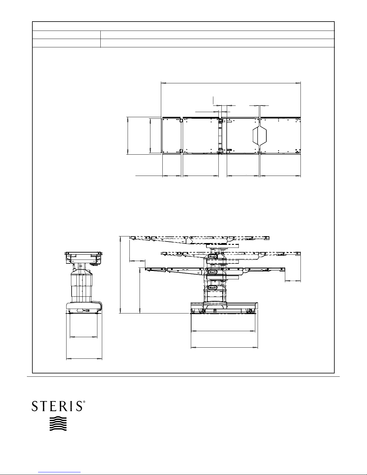
81” (2055mm)
22” (550mm)
13”
(325mm)
22”
(570mm)
22”
(550mm)
24”
(610mm)
3” (80mm)
Dimensionsaretypical-
drawing is not to scale.
Tabletop Dimensions
Dimensions are inches (mm). Society of
Automotive Engineers (SAE) measurements
are approximate based on metric dimensions.
25”
(635 mm) 13”
(330 mm) 43”
(1090 mm)
43”
(1088 mm) 13”
(330 mm) 25”
(637 mm)
Column
Column
Dimensions are inches (mm). SAE
measurements are approximate based on
metric dimensions.
Dimensions are typical -
drawing is not to scale.
Image Amplification Coverage (Typical)
4
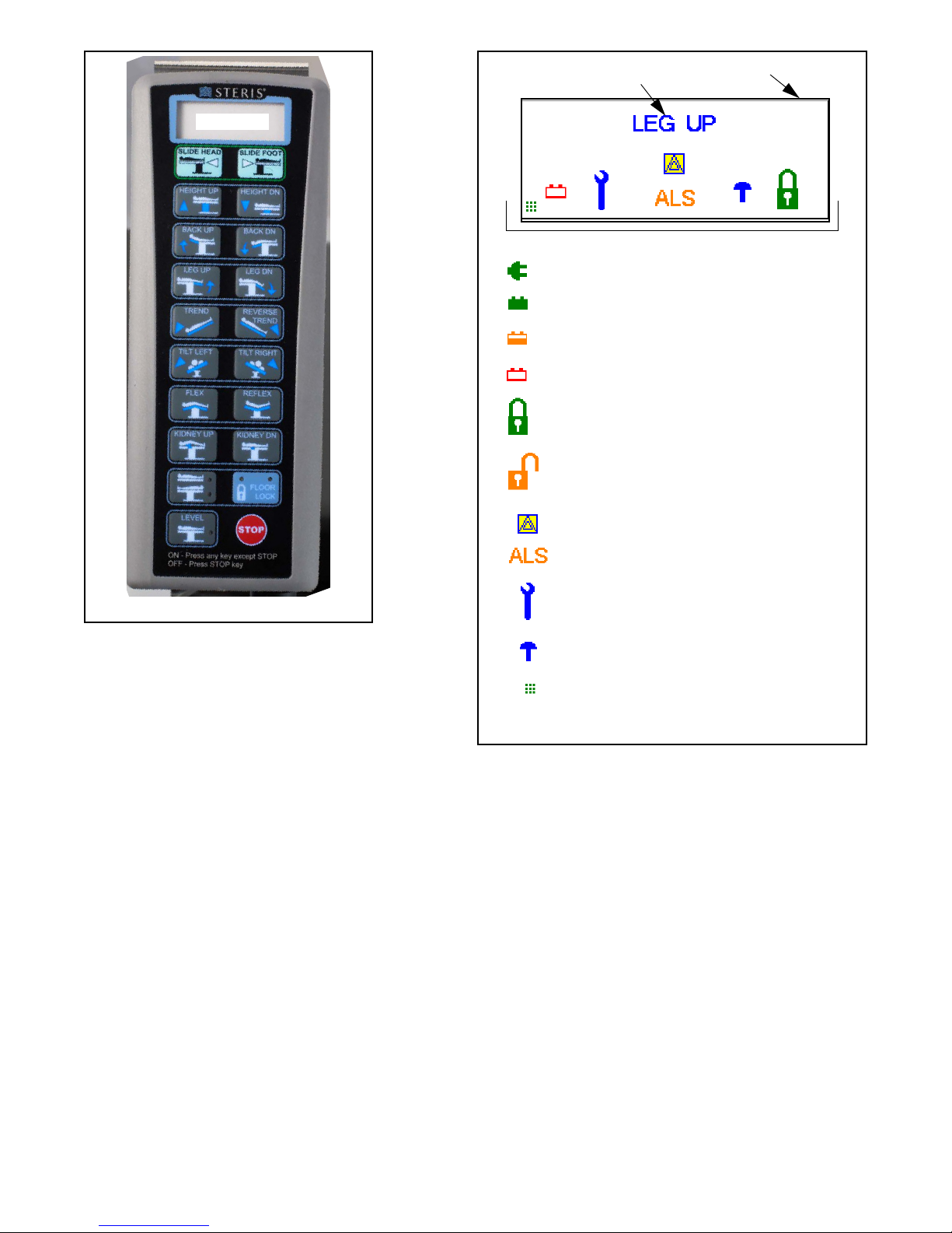
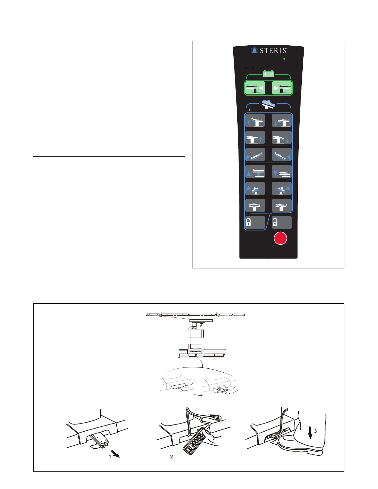
Pendant Primary Hand Control (see illustration) is
ergonomically designed. This intuitive primary interface for
table operation is constructed of one-piece thermoformed
plastic that holds and seals the keypad (illuminated for easy
table articulation identification when room is dark). Hand
Control is equipped with a 12' (3.7 m) long cord (3' [0.9 m]
when coiled) that plugs into a receptacle located at the top of
the column. Membrane touch switches provide, through an
auxiliary CPU, input signals to activate table functions and
articulations. LED indicators and LCD Display (validates table
positioning, eliminating the need to lift sterile drape to confirm
table position) provide the following table operation
information:
LCD includes:
• Auto Limit Sensor Notification (Icon and Text)
• Battery Power (Full, Half, Empty)
• AC (Facility) Power
• Kidney Bridge
• Floor Lock Position (Locked, Unlocked)
• Maintenance Notification
• Keypress
• Slide (Icon and Number)
• Tabletop Positioning
Touch Pads include:
• SLIDE HEAD/FOOT
• HEIGHT UP/DN
• BACK UP/DN
• LEG UP/DN
• TREND/REVERSE TREND
• TILT LEFT/RIGHT
• FLEX/REFLEX
•KIDNEYUP/DN
• LEVEL
• FLOOR LOCK (Lock and Unlock)
•STOP
LEDs include:
• FLOOR LOCK
• NORMAL and REVERSE Patient Orientation
• LEVEL
Primary Hand Control
LCD Display
Primary Hand Control Symbols
Primary Hand Control LCD Display and Symbols
Tabletop Positioning
AC (Facility) Power
Full Battery
Half Battery
Empty Battery
Locked
Unlocked
ALS Notification (Icon and Text)
Maintenance Notification
Kidney Bridge
Keypress
LCD Display
5
Backup (Override) Control System can be actuated at any
time and allows table operation in the event of primary control
or power malfunction. The controls are located beneath a cover
plate and stored in a convenient drawer (see illustration). A
pedal (foot pump to provide hydraulic power) and Backup
Hand Control (see illustration) comprise this system. Included
functions on Override Hand Control are: SLIDE HEAD/FOOT,
BACK UP/DN, LEG UP/DN, TREND/REVERSE TREND, HEIGHT
UP/DN, TILT LEFT/RIGHT, KIDNEY UP/DN, FLOOR LOCK/
UNLOCK and STOP switch.
FLOOR UNLOCK and SLIDE functions do not require foot pump
actuation. A green LED on the Backup Hand Control indicates
the system is active.
TABLE OPERATION
Press the desired position touch pad on the pendant hand
control or optional foot control to position/articulate the STERIS
4085 General Surgical Table tabletop (refer to Operator
Manual).
The following pre-operative actions must be completed before
the table can be used:
•Power activation: Use battery power or plug the table
power cord into both table base and facility ac power
receptacle. Toggle Main Power Switch to ON for facility
power.
•Turn the table on: Press any button on the hand control to
turn table ON. Hand control remains powered for 10 hours
from last button press.
•Lock the table: Press and hold the FLOOR LOCK button
on the Hand Control for one second to order the floor locks
into the "locked" position.
Auto Limit Sensor™ control device (using Intelligent Limit
Sensors) provides instant user feedback on conflicting tabletop
articulations and how to resolve the conflict when the table is
positioned in standard configuration.
TREND REVERSE
TREND
HEIGHT UP HEIGHT DN
BACK UP BACK DN
LEG UP LEG DN
FLOOR
LOCK
STOP
CAUTION
Back-up mode
Auto Limit Sensors NOT available
USE WITH FOOT PUMP
SLIDE HEAD SLIDE FOOT
KIDNEY UP KIDNEY DN
FLOOR
UNLOCK
TILT LEFT TILT RIGHT
Backup (Override) Hand Control
C-MAX 05
Ensurecapscover
socketswhennotinuse.
SERVE
Dimensions are typical -
drawing is not to scale.
Auxiliary Control System

6
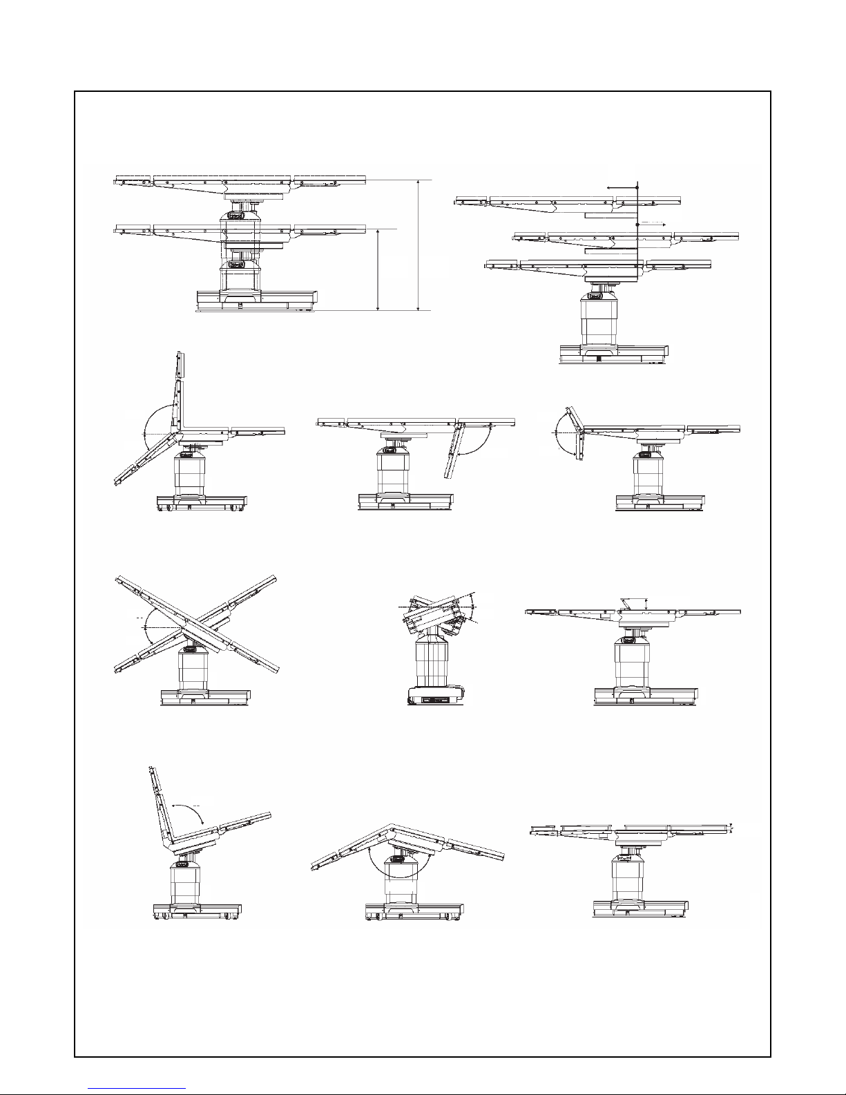
TABLE MOTION
Refer to illustration on next page for the following ranges of
table motion:
• Flex/Reflex: 140°/100°
• Slide Motion: HEAD: 9" (227 mm)
FOOT: 9" (227 mm)
• Height Range: 26 to 45" (660 to 1143 mm)
• Trendelenburg Range: 30°±1°
• Reverse Trendelenburg Range: 30°±1°
• Tilt Range: 20°±1°
• Back Section Motion: UP: 80°±1°
DOWN: 40°±1°
• Leg Section Motion: UP: 0°
DOWN: 105°±1°
• Kidney Elevator Mechanism: 4" (110 mm)
PREVENTIVE MAINTENANCE
Customers are encouraged to contact STERIS concerning our
comprehensive preventive maintenance program. Under the
terms of this program, preventive maintenance, adjustments
and replacement of worn parts are provided on a scheduled
basis to help ensure optimal equipment performance and help
avoid untimely or costly interruptions. STERIS maintains a
global staff of well equipped, factory-trained technicians to
provide these services, as well as expert repair services. Please
contact STERIS for details.
NOTES
1. Approximate Table Operating Weight: 560 lbs (250 kg).
2. Latex-free pads are standard for this table.
3. Patient Weight Capacity:
•1100 lb (499 kg) load; without patient positioning (no
tabletop articulation or slide).
•1000 lb (454 kg) load; includes all patient positioning
except tabletop slide.
•600 lb (272 kg) load; includes all patient positioning and
full tabletop slide.
4. STERIS 4085 table accessories have specific weight claims/
capacities. Accessories may reduce table patient weight
capacity. Refer to specific accessory Operator Manual or
contact STERIS for details.
5. A patient grounding post/potential equalization terminal
(male connector, DIN 42801) is provided with the table. The
female connector for patient grounding is not furnished by
STERIS.
6.WARNING–EXPLOSIONHAZARD:Tablemustnotbeused
in the presence of flammable anesthetics.
UTILITY REQUIREMENTS
Power Source:
Battery/Electric-Powered Table
Line Power Input:
100/120/220/230-240 V ac (Jumper Selectable), 1 Ø, 50/60 Hz,
4 Amp
Environmental Conditions:
Temperature: 32-122°F (0-50°C)
Relative Humidity (RH): 20-80%
CUSTOMER IS RESPONSIBLE FOR COMPLIANCE WITH
APPLICABLE LOCAL AND NATIONAL CODES AND
REGULATIONS.
ThebaselanguageofthisdocumentisENGLISH.Anytranslations
must be made from the base language document.
7
Dimensions are inches (mm). SAE
measurements are approximate based on
metric dimensions.
Dimensions are typical -
drawing is not to scale.
90°
26
(660)
45
(1143)
9
(227)
9 (227)
80°
40° 105°
90°
90°
30°
30°
20°
20°
4 (110)
100°
140°
2 (51)
STERIS 4085 General Table Range Of Motion (Typical)
For Further Information, contact:
Global Headquarters
STERIS Corporation
5960 Heisley Road
Mentor, OH 44060-1834 • USA
440-354-2600 • 800-548-4873
www.steris.com
SD909 ©2016, STERIS Corporation. All rights reserved. (02/01/16)
This document is intended for the exclusive use of STERIS Customers, including
architects or designers. Reproduction in whole or in part by any party other than
a Customer is prohibited.
Reference the following equipment drawing for installation details
Equip. Dwg. No. Equipment Drawing Title
150832-642 STERIS 4085 General Surgical Table
81
(2057)
22
(547)
20
(508)
11
(275)
21
(525)
19
(470)
23
(595)
1/2
(15)
3
(80)
2
(43)
16
(401)
21
(525)
45
(1143) 26
(660)
9
(227)
9
(227)
37
(940)
39
(984)
WARNING – EXPLOSION HAZARD: Table must not be used in the presence of flammable anesthetics.
Dimensions are typical -
drawing is not to scale. Dimensions are inches (mm). SAE measurements are
approximate based on metric dimensions.
Other manuals for 4085
2
Table of contents
Popular Indoor Furnishing manuals by other brands

Regency
Regency LWMS3015 Assembly instructions

Furniture of America
Furniture of America CM7751C Assembly instructions

Safavieh Furniture
Safavieh Furniture Estella CNS5731 manual

PLACES OF STYLE
PLACES OF STYLE Ovalfuss Assembly instruction

Trasman
Trasman 1138 Bo1 Assembly manual

Costway
Costway JV10856 manual


