19 20 21
31 12
4 5 6 7 8 9 10 11
1713 18
14 15 16
2
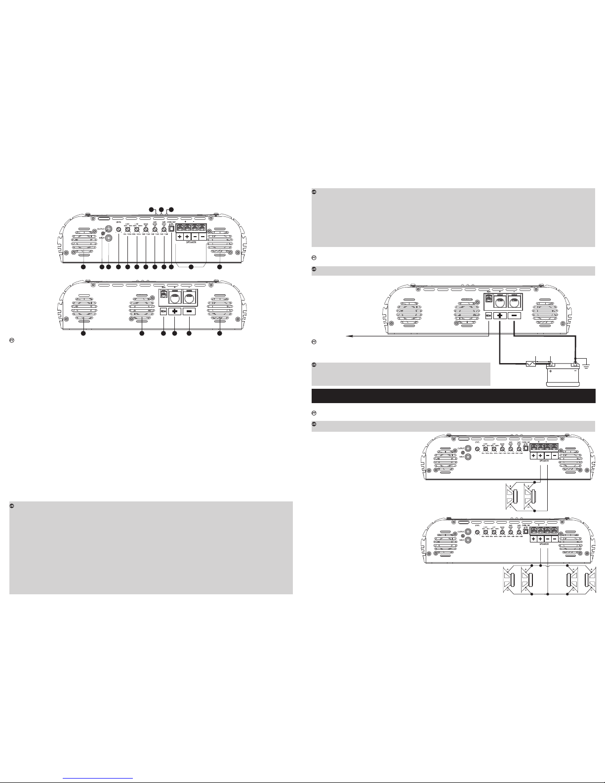
ENTRADA DE ÁUDIO, CONTROLES E SAÍDA DE ÁUDIO AMPLIFICADA /
AUDIO INPUT, CONTROLS AND AMPLIFIED AUDIO OUTPUT
DESCRIÇÃO GERAL / OVER VIEW
ENTRADA DE VENTILAÇÃO E ALIMENTAÇÃO / VENT AND POWER SUPPLY
COM 2 ALTO-FALANTES
WITH 2 SPEAKERS
Os cabos dos alto-falantes deverão ser polarizados (marcados) para facilitar a identificação de positivo e negativo. A bitola mínima é de 4mm².
Mantenha os cabos dos alto-falantes bem isolados. Cuidado com partes metálicas que podem danificar a isolação dos cabos.
The speaker cables should be polarized (marked) in order to facilitate identifying which is positive and which is negative. Minimum gauge is 4mm².
Keep the cables well insulated, and avoid metal parts, as these may damage the insulation.
1/12/14) COOLER: Este ventilador irá funcionar de acordo com o volume do CD/DVD/MP3-Player, ou seja, quanto maior for o volume, maior será a
velocidade do ventilador. Sistema de ventilação controlado por áudio. FAN CONTROLLED BY AUDIO.
2) OUTPUT - SAÍDA RCA: Esta saída poderá ser utilizada opcionalmente para tocar outro amplificador, facilitando a instalação em sistemas multi-amplificados.
3) INPUT - ENTRADA RCA: Esta entrada deverá receber o sinal através de um cabo RCA que deverá estar conectado à saída RCA do CD/MP3-Player.
4) LEVEL - CONTROLE DE NÍVEL: Controla o nível do sinal de entrada, permitindo uma regulagem adequada a qualquer CD/MP3-Player existente no
mercado. Para fins práticos poderá ser regulado da seguinte forma:
a) no CD/MP3-Player, coloque um sinal musical qualquer e posicione o volume em 80% do máximo.
Por exemplo: se o máximo do volume do CD/MP3-player é 45 (100%), ajuste para 36 (80%).
b) no amplificador, a partir do LEVEL no mínimo, aumente gradativamente até o led de clipping começar a piscar.
c) retorne devagar o LEVEL até que o led apague completamente. (Observar o item 9 OVER CLIP)
5) HIGH PASS FILTER - FILTRO PASSA ALTA: Proporciona um corte nos sons de baixa freqüência (subsônicos). Este filtro é muito útil quando se utiliza
alto-falantes do tipo woofers. Nestes casos, os woofers não são capazes de reproduzir os subsônicos, podendo até danificar dependendo da potência e
música utilizada. Sua regulagem varia de 10Hz a 700Hz.
6) LOW PASS FILTER - FILTRO PASSA BAIXA: Este controle varia a freqüência de corte do filtro dos canais (crossover) de 50Hz a 10KHz. Este filtro
permite passar apenas os sons abaixo da freqüência de corte.
7) BASS: Este controle proporciona ganho/atenuação de ±10dB nas frequências de som graves. Frequência central de 45Hz.
8) MID-BASS: Este controle proporciona ganho/atenuação de ±10dB nas frequências de som médio-graves. Frequência central de 270Hz.
9) MID-HIGH: Este controle proporciona ganho/atenuação de ±10dB nas frequências de som média-alta. Frequência central de 2KHz.
10) OVER CLIP - ON / OFF: Com esta chave ligada, o LED de Cliping acenderá com 15% mais de potência final.
11) SAÍDA PARA ALTO-FALANTES: Esta saída é MONO. Cuidado com a polaridade correta das conexões com os alto-falantes e verifique a impedância
mínima permitida nesta saída. Utilize cabos de no mínimo 10 mm².
13/18) VENTILAÇÃO: Permite a saída do ar aquecido do amplificador.
15) REM - ACIONAMENTO REMOTO: Conecte o terminal REM à saída para antena elétrica do seu CD/MP3-Player. Assim quando ligar seu CD/MP3-
Player, o amplificador automaticamente ligará. Um cabo de 0.5 mm² é suficiente.
16) “+” +BAT - ALIMENTAÇÃO POSITIVA: Conecte o terminal ( “+” +BAT) ao pólo positivo da bateria (+12V) com um cabo de no mínimo 70,0mm². É
extremamente importante que seja utilizado um fusível ou disjuntor de proteção neste cabo a uma distância máxima de 30 cm da bateria. O
fusível ou disjuntor deverá ser no mínimo igual ao valor máximo de corrente consumida com sinal musical (vide tabela de especificações
técnicas).
17) “-” CONEXÃO DE TERRA: Utilize cabo de no mínimo 70,0mm². Conecte o cabo no chassi do veículo.
OBS: sempre ligue o fio GND ( - ) do CD-Player, ou outros aparelhos no mesmo ponto.
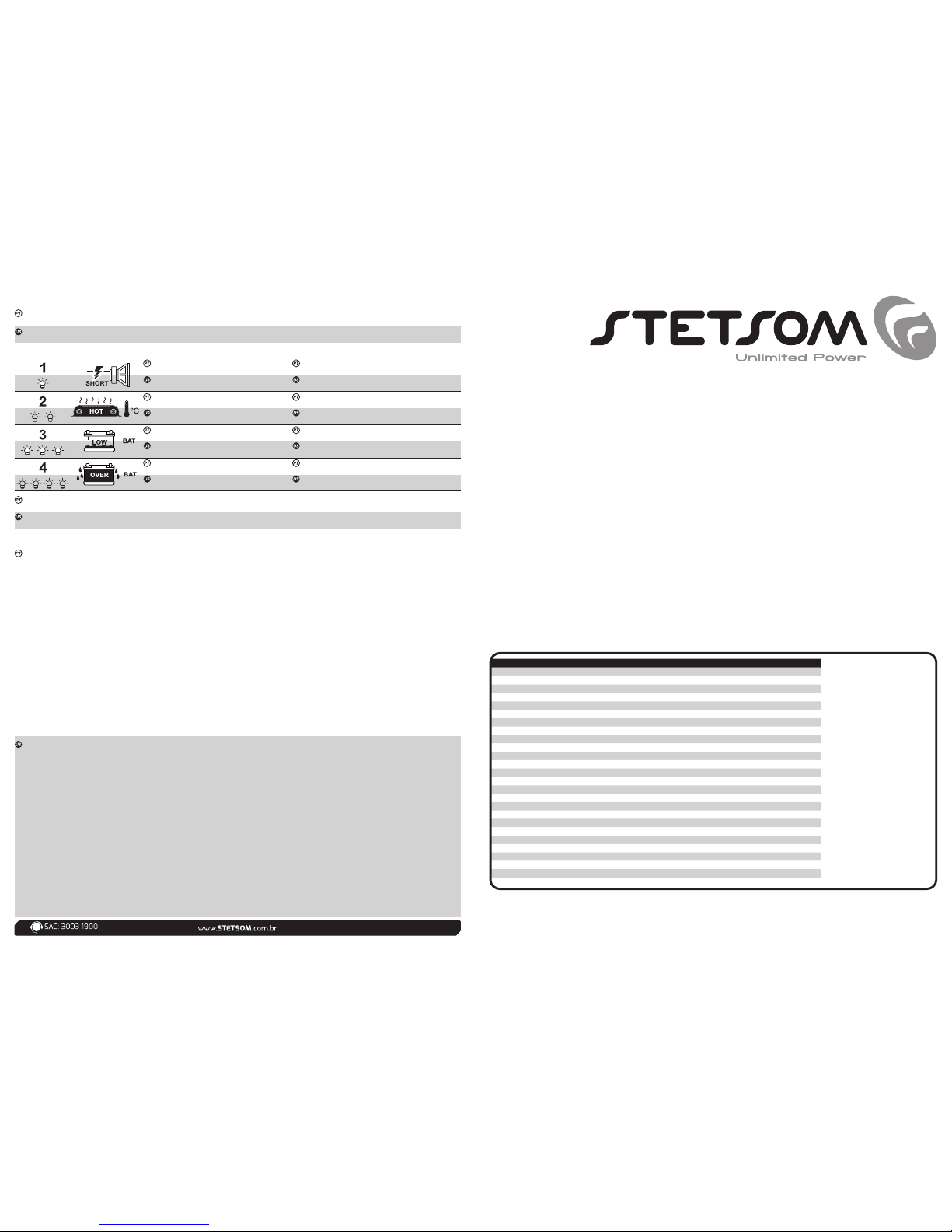
19) POWER LED (AZUL): O led indicador acenderá quando o aparelho for acionado pelo sinal remoto vindo do CD/MP3-player.
20) PROT LED (VERMELHO): O Led acenderá nas seguintes situações (Vide Tabela de diagnósticos “Contra Capa”):
a) Curto-circuito nas saídas de alto-falantes c) Baixa tensão da bateria
b) Temperatura acima da permitida. d) Alta tensão da bateria
21) CLIP LED (VERMELHO): O Led acenderá quando o sinal de saída começar a distorcer.
1/12/14) COOLER: This fan will operate according to the volume of the CD/DVD/MP3 player. The higher the volume, the higher speed at which the fan will
run. The ventilation system is controlled by audio. FAN CONTROLLED BY AUDIO.
2) OUTPUT - RCA OUTPUT: This output can be used optionally to play another amplifier, facilitating installation in multi-amplified systems.
3) INPUT - RCA INPUT: This input should receive the signal through an RCA cable connected to the output of the CD/MP3 player.
4) LEVEL - LEVEL CONTROL: Controls the input signal level, allowing for proper control of any CD/MP3 player currently on the market. It can be regulated
as the following:
a) on the CD/MP3 player, play any musical signal up to 80% volume (ie. If the maximum volume on the player is 45 [100%], adjust to 36 [80%]).
b) on the amplifier, beginning at the lowest LEVEL, gradually increase until the clipping LED begins to flash.
c) slowly decrease the LEVEL until the LED goes off. (see entry 9 OVER CLIP)
5) HIGH PASS FILTER: Allows cut off of low frequency (subsonic) signals. This filter is very useful for woofer-type speakers. In these cases, the woofers are
not capable of reproducing subsonic frequencies, and these subsonic frequencies may even cause damage depending on the volume and the music
played. It is regulated from 10Hz to 700Hz).
6) LOW PASS FILTER: This control varies the cut off frequency from 50Hz to 10KHz.This filter allows to pass only sounds beneath the cut frequency.
7) BASS: This control provides gain/attenuation of ±10dB in low frequency. Central frequency is 45Hz.
8) MID-BASS: This control provides gain/attenuation of ± 10dB in mid-low frequency. Central frequency is 270 Hz.
9) MID-HIGH: This control provides gain/attenuation of ±10dB in mid-high frequency. Central frequency is 2KHz.
10) OVER CLIP – ON/OFF: With this key turned on, the clipping LED will light up at 15% more final capacity.
11) SPEAKER OUTPUT: This output is MONO. Be careful of maintaining the correct polarity of the connections between the speakers and check the
minimum impedance of this output. Use cables with a minimum gauge of 10 mm² .
13/18) VENTS: Allows for the removal of warm air from the amplifier.
COM 4 ALTO-FALANTES
WITH 4 SPEAKERS
11K2 EQ - 1 OHM: 4 x 4 OHMS
INSTALAÇÃO DA ALIMENTAÇÃO / POWER SUPPLY INSTALLATION (BATTERY)
INSTALANDO OS CABOS DE ENTRADA / INSTALLING THE INPUT CABLES
ATENÇÃO: O USO DO DISJUNTOR OU FUSÍVEL EXTERNO É OBRIGATÓRIO, JÁ QUE O AMPLIFICADOR NÃO POSSUI FUSÍVEL INTERNO.
ATTENTION: THE USE OF THE FUSE OR BREAKER IS REQUIRED, SINCE THIS AMPLIFIER HAS NO INTERNAL FUSES.
DISJUNTOR ou
FUSÍVEL: 500A
FUSE or
CIRCUIT BREAKER CHASSI
ACIONAMENTO REMOTO
REMOTE CONTROL
BATERIA
BATTERY
12V
MÁX
30 cm
INSTALAÇÃO DA SAÍDA DE ALTO-FALANTES / INSTALLATION OF THE SPEAKER OUTPUTS
Para a instalação da alimentação, utilize cabos com bitola de 70mm². O cabo positivo
devera vir direto da bateria, com um fusível ou disjuntor de proteção localizado a 30cm da
bateria. O cabo negativo deverá ter a mesma bitola do positivo, e parafusado no chassi do
veiculo, tomando-se o cuidado de evitar tinta e ferrugem que poderão impedir a passagem da
corrente elétrica, causando perda de potência e ruídos no som.
In order to install the power supply, use cables with a gauge of 70mm². The positive cable
should come straight from the battery, with a fuse or protective breaker 30cm from the battery.
The negative cable should have the same gauge as the positive cable, and should be screwed
to the chassis of the vehicle, taking caution to avoid paint and rust. These may interfere with the
flow of the electrical current, causing loss of power and interference in the sound.
Para a ligação de entrada, utilize cabos blindados com conectores tipo RCA nas extremidades. Utilize cabos de boa qualidade, próprios para áudio,
para evitar a captação de ruídos indesejados.
For the input connection, use shielded cables with RCA plugs. Use quality cables, specific for audio, to avoid interference from unwanted noise sources.
(Recomendamos os Cabos RCA com Blindagem Tripla - STETSOM) / (We recommend the RCA cables with Triple shielding - STETSOM)
14) “+” +BAT: Connect the terminal (“+” +BAT) to the positive terminal of the battery (+12V) with a minimum gauge of 70mm². It is extremely important that
a protective fuse or circuit breaker be used on this cable at a distance of 30 cm from the battery. The fuse or circuit breaker should be, at
minimum, equal to the max current consumption value caused by playing musical signals (see technical specifications table).
15) REM - REMOTE CONTROL: Connect the REM terminal to the electric antenna output of the CD/MP3 player. This will cause the amplifier to turn on
automatically when you turn on your CD/MP3 player. A cable with a gauge of .5mm² is adequate.
16) “- “ GROUND CONNECTION: Use a cable with a gauge of at least 70mm². Connect the cable to the chassis of the vehicle.
(Note: always connect the GND wire [-] of the CD player—or other equipment—to the same ground point.)
19) POWER LED (BLUE) : This indicator LED will light up when it is activated by the remote control signal from the CD/MP3 player.
20) PROT LED (RED): This LED will light up for the following reasons (see the diagnostic table on the back cover):
a) Short circuit in the speakers c) Low battery voltage
b) Excessive temperature d) High battery voltage
21) CLIP LED (RED): This LED will light up when the signal begins to suffer distortion.
11K2 EQ - 1 OHM: 2 x 2 OHMS
11K2 EQ
11K2 EQ
11K2 EQ
11K2 EQ
11K2 EQ