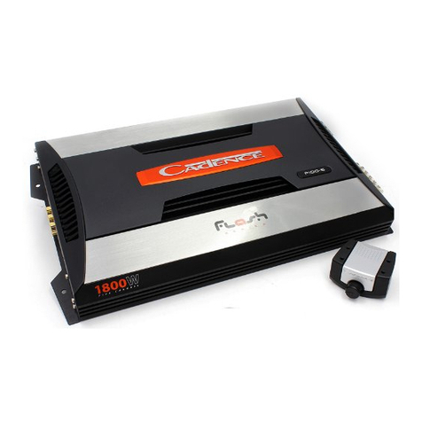
StetSom S 35 User manual

Nov/2011 - REV 1A
Channels: 1 1
Power RMS: 35.200 Watts (1 OHM) @ 250V 34.500 Watts (0,5 OHM*) @ 176V
Power RMS: 17.600 Watts (2 OHMs) @ 250V 17.250 Watts (1 OHM) @ 176V
Power RMS: 8.800 Watts (4 OHMs) @ 250V 8.620 Watts (2 OHMs) @ 176V
Maximum Supply Voltage: 315V 176V
Frequency Response: 20 Hz to 2KHz
Crossover Low Pass: 50 Hz to 2KHz
Subsonic Filter: 20Hz to 80 Hz
Total Harmonioc Distortion: < 1%
Signal to Noise: > 90 dB
Sensitivity Minimum Input: 0,2V
Input Impedance: 20K OHMS
Minimum Output Impedance:
20 Batteries - 250V 1 OHM -
14 Batteries - 176V - 0,5 OHM
Bat. Automotive / Signal Musical: 50A 50A
Bat. Stationary / Sinal Musical: 100A 100A
Consumption / Sinal BASS: 190A
Consumption Max @ 12,6V: 20A
Dimensions (A x L x C) mm: 77 x 525 x 355
Weight: 13 Kg
SPECIFICATIONS
Line
High
Voltage
MODELO: S 35 1 OHM 0,5 OHM
NOTE: THE ABOVE SPECIFICATIONS ARE RELATED TO A SINGLE PRODUCT. SPEAKER IS DIVIDED IN
2 TO FACILITATE UNDERSTANDING OF THE VARIOUS APPLICATIONS (1 OHM and 0.5 OHM).
(* - 0,5 OHM = RE)
NOT TURN ON:
- The cables are not properly connected (terminals +BATT, GND and REM). Make sure that all connections
are mechanical and electrical contact.
- Fuses / breakers (external) are defective or burned. Pay attention to the correct value of the new fuse!
NO SOUND:
- The cables of the speakers or RCA plugs are not connected correctly.
- Check that the LEVEL control is not in the minimum.
NO SOUND/PROTECTION RED LED FLASHING:
- See diagnosis UP (SYSTEM TROUBLESHOOTING).
- The speakers or cables defectives thus check the speakers, cables and connections.
POOR SOUND QUALITY (DISTORTION):
- The speakers are overloaded, therefore decrease the level and redo the gain setting (See item 2 /
OVERVIEW).
WEAK BASS:
- Cables speakers (+) and (-) are reversed, speaker out of phase (see Section 7 / overview).
MOTOR NOISE, HORN, SIGNAL LIGHT, ETC:
- Use suppressive cables in ignition candles.
- Use capacitors in the alternator, horn and ignition.
- Pass the RCA cable away from any other cable, because it is more sensitive to interference.
- Connect to power (+12 V) to separate the sound system. Use a fuse to 30 cm from the battery for
protection.
- Make a good grounding of the amplifier. To do this removes the paint from the chassis of the vehicle at the
desired point. Screw the cable using a ground terminal. To protect from oxidation, insulate with paint.
- Do not loop the ground wire. Avoid using several ground wires. Prefer a star connection, with all the
ground wires aside from a single point.
WHAT TO DO IN CASE OF PROBLEMS
USER’S GUIDE
NOTICE
THIS PRODUCT
THREATENING
DEATH.
INDICATED ONLY
FOR PEOPLE
SPECIALIST.
DANGER
HIGH
VOLTAGE
www.stetsom.com - [email protected]

LEDS INDICADORES
1 6
1) SPEAKERS OUTPUT: This output is MONO. Beware of the polarity of the connections with the speakers
and check the minimum impedance allowed in this output. The minimum battery 20 is permitted to 1 ohm
and 14 batteries is 0.5 ohm. Use cables of at least 16mm ².
2) LOW PASS FILTER: This control varies frequency cut filter 50Hz to 2KHz. This filter allows passing only
the sounds below the cut off frequency.
3) SUB SONIC FILTER: Provides a cut in the low frequency sound (subsonic). This filter is very useful
when using speakers model woofers. In these cases, the woofers are not able to reproduce the subsonic
and may even damage depending on the power and music used. Its adjustment varies from 20Hz to 80Hz.
4) LEVEL - GAIN CONTROL: Controls the level of the input signal, allowing a proper adjustment to any
CD/MP3-Player of the market. For practical purposes may be adjusted as follows:
a) CD/MP3-Player, put a musical signal and adjust the volume in 80% of maximum. For example, if
the maximum volume of CD/MP3-player is 45 (100%), adjusting for 36 (80%).
b) In the amplifier, from the LEVEL at least, increase gradually until the clipping LED flashes.
c) Return the LEVEL slowly until the LED delete completely.
5) OUTPUT – SAÍDA RCA: Esta saída poderá ser utilizada opcionalmente para tocar outro amplificador,
facilitando a instalação em sistemas multi-amplificados.
6) INPUT - INPUT RCA L and R: This entry should receive the signal by RCA cable that must be connected
to the output RCA of CD/MP3-Player.
7) REM - DRIVE REMOTE: Connect the REM terminal to output for remote / antenna electric of CD/MP3-
Player. So when you turn on your CD/MP3-Player, the amplifier automatically turns on. A cable of 0.5 mm²
is sufficient.
8 12 12 6) + : Connect the terminal (+ ) to the positive pole of the battery (+12 V) with a cable of at least .0
mm². It is extremely important that you use a fuse or circuit breaker to protect this cable to a maximum
distance of 30 cm from the battery.
9) + HIGH VOLTAGE - POSITIVE POWER (PACK OF BATTERIES IN SERIES): Connect the (+ HIGH
VOLTAGE) to the positive battery last block with a cable of at least 21mm ².
It is extremely important that you use a fuse or circuit breaker protection for each four batteries
connected in series and a final fuse or circuit breaker between the battery pack and amplifier.
10) GND - GROUND CONNECTION: Use cable with 21.0 mm².Plug the cable into the chassis of the
vehicle.
NOTE: Always connect the cable GND (-) of CD-Player, or other devices at the same point.
11) COOLER: Cools the internal components of the amplifier. The air enter in the cooler and exits through
the exhaust ventilation.
AUDIO INPUT, CONTROLS AND OUTPUT SOUND
GENERAL DESCRIPTION
2 3 4 5 6
1
AIR INPUT AND POWER
7 8 9 10 11
Note: If only the RED LED blinks (BLUE LED OFF), turn on the device with the volume of CD/MP3-player down. If
the problem persists, please contact us.
SYSTEM TROUBLESHOOTING
- RED LED (PROT) illuminates only when
there is a problem in the functioning of
the device.
- RED LED (CLIP) flashes when
the amplifier output begin to
distort the sound.
- BLUE LED (POWER)
lights when the power
is on.
If some problem occurs, the amplifier will shut down and the RED LED will flash alternately with the BLUE LED. As
the problem occurred, the BLUE LED will blink a certain number of times. So we have a diagnosis according to the
table below:

3 4
INSTALLATION OF POWER (BATTERY) - 250 Volts and 12Volts
ATTENTION: USE OF THE EXTERNAL CIRCUIT
BREAKER OR FUSE IS REQUIRED, SINCE THE
AMPLIFIER HAS NO INTERNAL FUSE.
BATTERY
12V
CIRCUIT BREAKER 100A
CIRCUIT
BREAKER 100A
CIRCUIT BREAKER
100A
CIRCUIT BREAKER 100ACIRCUIT BREAKER 100ACIRCUIT BREAKER 100A
REMOTE TURN ON
BATTERY
12V BATTERY
12V
BATTERY
12V
BATTERY
12V
BATTERY
12V BATTERY
12V BATTERY
12V BATTERY
12V
BATTERY
12V BATTERY
12V BATTERY
12V BATTERY
12V
BATTERY
12V BATTERY
12V BATTERY
12V BATTERY
12V
BATTERY
12V BATTERY
12V BATTERY
12V BATTERY
12V
MÁX 30CM
NOTICE
THIS PRODUCT
THREATENING
DEATH.
indicated only
FOR PEOPLE
SPECIALIST.
21mm²
6mm²
6mm²
6mm²
35mm²
35mm²
35mm²
35mm²
35mm² 35mm²
35mm²
35mm²
35mm²
35mm²
35mm²
35mm²
35mm² 35mm²
35mm² 35mm²
35mm² 35mm²
35mm²
21mm²
21mm²
GROUND
COMMON TO ALL
SYSTEM
AMPLIFICATION
GROUND
COMMON TO ALL
SYSTEM
AMPLIFICATION
HIGH VOLTAGE
BATTERY PACK
HIGH VOLTAGE - PACK BATTERIES
1 OMH - 20 BATTERIES
0,5 OMH - 14 BATTERIES
CD / MP3 / DVD-Player
REM
REMOTE TURN ON
BATTERY
12V
FUSE 20A MÁX 30CM
Amplifiers
CD
STETSOM - VOL. 1
FUSE 20A
For the installation of power, choice of gauge 21mm² cable for high voltage (+250 V), 35mm²
connections between batteries in order to reduce losses and connections between 6mm ² for low
voltage (12V). 0s positive cable should come straight from the batteries, each with its own fuse or
circuit breaker protection. The negative high-voltage cable shall have the same gauge positive.
Please read this manual carefully before installing the device. The installing instructions and
connections must be followed in a precise way. If necessary consult our factory.
Every connection, battery , output signal for the speakers and input signal, can be made easily by
screwing terminals and RCA connectors.
1. Maintain the system cables as short as possible with correct gauge cables, this way you minimize
loss of Power and obtain a hi volume system.
2. For security reasons use proper cables for Speakers and Power.
3. For not damaging the cables avoid passing them trough areas with sharpen edges and metallic
borders.
4. Avoid passing all cables near the ignition, electronics injection and starter key or they may cause
interference.
5. Install a fuse or circuit breaker on the positive cable of the battery at 30cm away from the post.
BEFORE INSTALLING
DANGER
HIGH
VOLTAGE

5
- POWER TABLE x SPEAKER IMPEDANCE FOR S35:
The table below show the relationship between total power and final impedance (RL) resulting from
the combination of speakers connected to the audio output from amplifier S35 for a given numbers
of batteries:
Note: These values are referenced to a distortion of 5% THD and were obtained using a sinusoidal
signal of 250 Hz. Remember that the maximum power obtained for the same amplifier playing music,
will be approximately 50% of the values shown above. The hatched area is prohibited to use, since
the output current line the speaker of amplifier exceeds 190A RMS, which could damage the
amplifier. The region of operation suggested by Stetsom is the column of 252V total battery voltage.
RL: is the final impedance | XL: is the reactive impedance of speakers association
RE: is the ohmic resistance from this association
- CURRENT TABLE x SPEAKER IMPEDANCE FOR S35:
The table below show the relationship between the total current delivered by the amplifier in your
speaker line and the final impedance (RL) resulting from the association of speakers connected to the
audio output of the amplifier S35 for a given numbers of batteries:
WITH 16 SPEAKER OF 4 OHMS
WITH 4 SPEAKERS OF 4 OHMS
WITH 8 SPEAKER OF 8 OHMS
SPEAKERS
8 (8 OHMS) = 1 OHM
SPEAKERS
4 (4 OHMS) = 1 OHM
SPEAKERS
16 (4 OHMS) = 1 OHM
INSTALLING THE INPUT CABLES.
For the input entrance, use quality RCA cables with shield to avoid interference from
the car.
The cables of the speakers should be polarized (marked) to facilitate the identification of positive and
negative. The circumference should be at least 16mm². Keep the cables from the speakers properly
insulated. Beware of metal parts that can damage the insulation of cables.
INSTALLATION OF OUTPUT SPEAKER
Forbidden: IRL > 190A
Forbidden: IRL > 190A
Other StetSom Car Amplifier manuals

StetSom
StetSom CL DIGITAL User manual
StetSom
StetSom 5K ES User manual
StetSom
StetSom IR280.1 User manual
StetSom
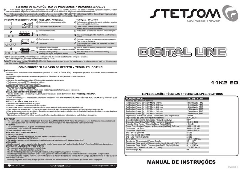
StetSom 11K2 ES User manual
StetSom
StetSom EXPORT Series User manual

StetSom
StetSom IR400.3 User manual

StetSom
StetSom V 200.2 User manual
StetSom
StetSom 6K5 ES User manual
StetSom
StetSom 11K2 EQ User manual
StetSom
StetSom V 400.4 User manual
Popular Car Amplifier manuals by other brands
Philips
Philips TDA1563Q datasheet
JL Audio
JL Audio NexD XD700/5 owner's manual
Boss Audio Systems
Boss Audio Systems R2002 user manual

Sony
Sony XM-2150GSX Marketing Specifications operating instructions

Soundstream
Soundstream PICASSO PiC2.240 user guide

Boss Audio Systems
Boss Audio Systems CHAOS CH650 Service manual

