STI FITNESS PR-7230 User manual

Product May Vary Slightly Different From Picture.
V. V
Owners’Manual
Exercise can present a
health risk. Consult a
physician before beginning
any exercise program with
this equipment.
If you feel faint or dizzy,
immediately discontinue use
of this equipment. Serious
bodily injury can occur if this
equipment is not assembled
and used correctly. Serious
bodily injury can also occur if
all instructions are not
followed.
Keep others and pets away
from equipment when in use.
Always make sure all bolts
and nuts are tightened prior
to each use. Follow all safety
instructions in this manual.
WARNING
CAUTION:
Weight on this product should not exceed 181 kgs/ 400 lbs
MADE IN TAIWAN
PR-7230

1
SAFETYINSTRUCTIONS
WARNING: Toreducethe risk ofseriousinjury, readthefollowingSafetyInstructionsbeforeusingthe
UprightBike.
1.ReadallwarningspostedontheRecumbentBike.
2.ReadthisOwner'sManualandfollowitcarefullybeforeusingtheRecumbentBike. Makesurethatitis
properlyassembledandtightenedbeforeuse.
3.Werecommendthattwopeoplebeavailableforassemblyofthisproduct.
4.KeepchildrenawayfromtheRecumbentBike. DonotallowchildrentouseorplayontheRecumbentBike.
KeepchildrenandpetsawayfromtheRecumbentBike whenitisinuse.
5.Itisrecommendedthatyouplacethisexerciseequipmentonanequipmentmat.
6.SetupandoperatetheRecumbentBikeonasolidlevelsurface.DonotpositiontheRecumbentBike on
looserugsoruneven surfaces.
7.InspecttheRecumbentBikeforwornorloosecomponentspriortouse.
8.Tighten/replaceanylooseorworncomponentspriortousingtheRecumbentBike.
9. Consultaphysicianpriortocommencinganexerciseprogram.If,atanytimeduringexercise,youfeelfaint,
dizzy,orexperiencepain,stopandconsultyourphysician.
10. Followyourphysician'srecommendationsindevelopingyourownpersonalfitnessprogram.
11. Alwayschoosetheworkoutwhichbestfitsyourphysicalstrengthandflexibilitylevel.Knowyourlimitsandtrain
withinthem.Alwaysusecommonsensewhenexercising.
12.Beforeusingthisproduct,pleaseconsultyourpersonalphysicianforacompletephysicalexamination.
13. DonotwearlooseordanglingclothingwhileusingtheRecumbentBike.
14. Neverexercise inbarefeetorsocks;alwayswearcorrectfootwear,suchasrunning,walking,or cross-training
shoes.
15. Becarefultomaintainyourbalancewhileusing,mounting,dismounting,orassemblingtheRecumbentBike,
lossofbalancemayresultinafallandseriousbodilyinjury.
16. KeepbothfeetfirmlyandsecurelyontheFootPedalswhileexercising.
17. TheRecumbentBike shouldnotbeusedbypersonsweighingover400 pounds/181 kgs.
18. TheRecumbentBikeshouldbeusedbyonlyonepersonatatime.
19.Maintenance:Replacethedefectivecomponentsimmediatelyand/orkeeptheequipmentoutofuseuntil
repairtheequipmentcompletely.
20. TheRecumbentBike iswell-suited tostudiouse(ClassS.)
21.MakesurethatadequatespaceisavailableforaccesstoandpassagearoundtheRecumbentBike;keepat
leastadistanceof1meterfromanyobstructionobjectwhileusingthemachine.
WARNING:Beforestartinganyexerciseorconditioningprogramyoushouldconsultwithyourpersonalphysician
toseeifyourequireacompletephysicalexam.Thisisespeciallyimportantifyouareovertheageof35,have
neverexercisedbefore,arepregnant,orsufferfromanyillness.READANDFOLLOWTHE SAFETY
PRECAUTIONS.FAILURE TOFOLLOW THESEINSTRUCTIONS CAN RESULT INSERIOUS BODILY
INJURY.
2
BEFORE YOU BEGIN
Thank you for choosing the self-powered Recumbent
Bike. We take great pride in producing this quality
product and hope it will provide many hours of quality
exercise to make you feel better, look better and enjoy
life to its fullest.
Yes, it's a proven fact that a regular exercise program
can improve your physical and mental health.
Too often, our busy lifestyles limit our time and
opportunity to exercise. The Recumbent Bike
provides a convenient and simple method to begin your
assault on getting your body in shape and achieving a
happier and healthier lifestyle.
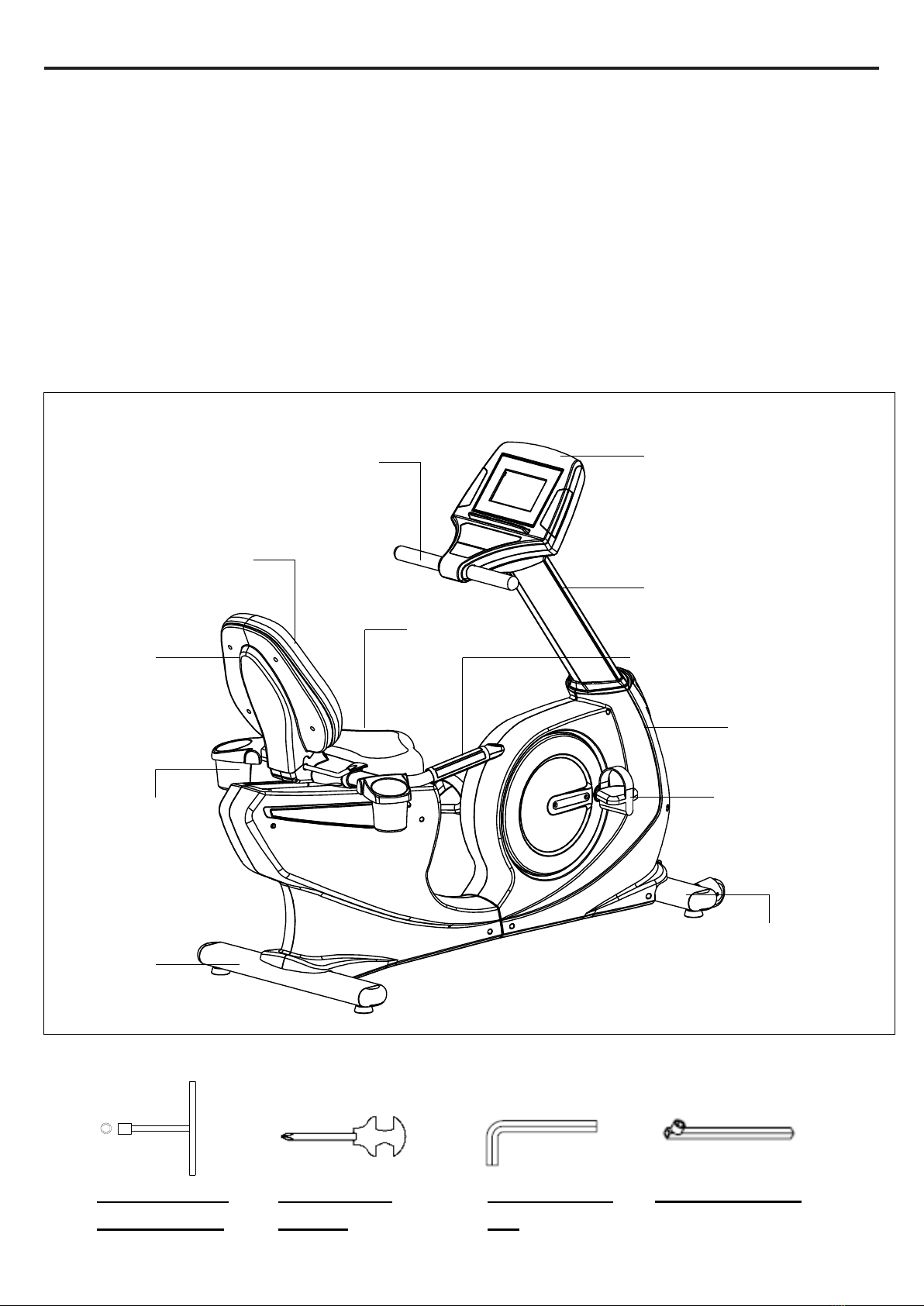
Before reading further, please review the drawing
below and familiarize yourself with the parts that are
labeled. Read this manual carefully before using the
RecumbentBike.
THE FOLLOWING TOOLS ARE INCLUDED FOR ASSEMBLY:
Upper Handlebar
Console
Upright Cover
Pedal
Seat Handlebar
Accessory Tray
Rear Stabilizer
Main Frame
Front Stabilizer
Back Cushion
Cover
Back Cushion
Seat
T-HAND SOCKET
WRENCH (17MM)
ALLEN WRENCH
(M6)
SOCKET WRENCH
COMBINATION
WRENCH
3
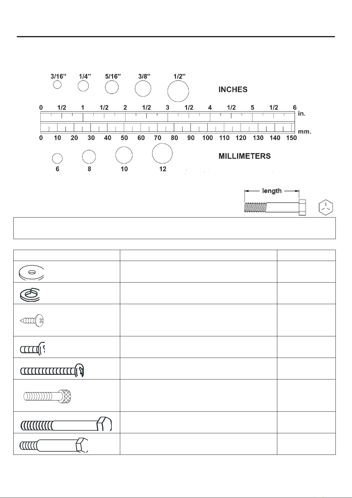
HARDWARE IDENTIFICATION CHART
This chart is provided to help identify the hardware used in the assembly process. Place the washers, the end of the bolts,
or screws on the circles to check for the correct diameter. Use the small scale to check the length of the bolts and screws.
NOTICE: The length of all bolts and screws except those with flat heads is measured from
below the head to the end of the bolt or screw. Flat head bolts and screws
are measured from the top of the head to the end of the bolt or screw.
After unpacking the unit, open the hardware bag and make sure that you have all the following items. Some hardware
may be already attached to the part.
Part No. and Description
Qty
85 Washer (8x38x2.0t)
4
90 Lock Washer (M8)
6
131 Screw (M4x10mm)
4
95 Screw, Round Head (M5xp0.8x15mm)
10
96 Screw, Round Head (M5xp0.8x50mm)
2
104 Bolt, Socket Head (M8xp1.25x50mm)
2
109 Bolt, Hex Head (M8xp1.25x65mm)
4
114 Bolt, Hex Head (M10xp1.5x50mm)
2
4
ASSEMBLE INSTRUCTIONS
Place all parts from the box in a cleared area and position them on the floor in front of you. Remove all packing
materials from your area and place them back into the box. Do not dispose of the packing materials until
assembly is completed. Read each step carefully before beginning.
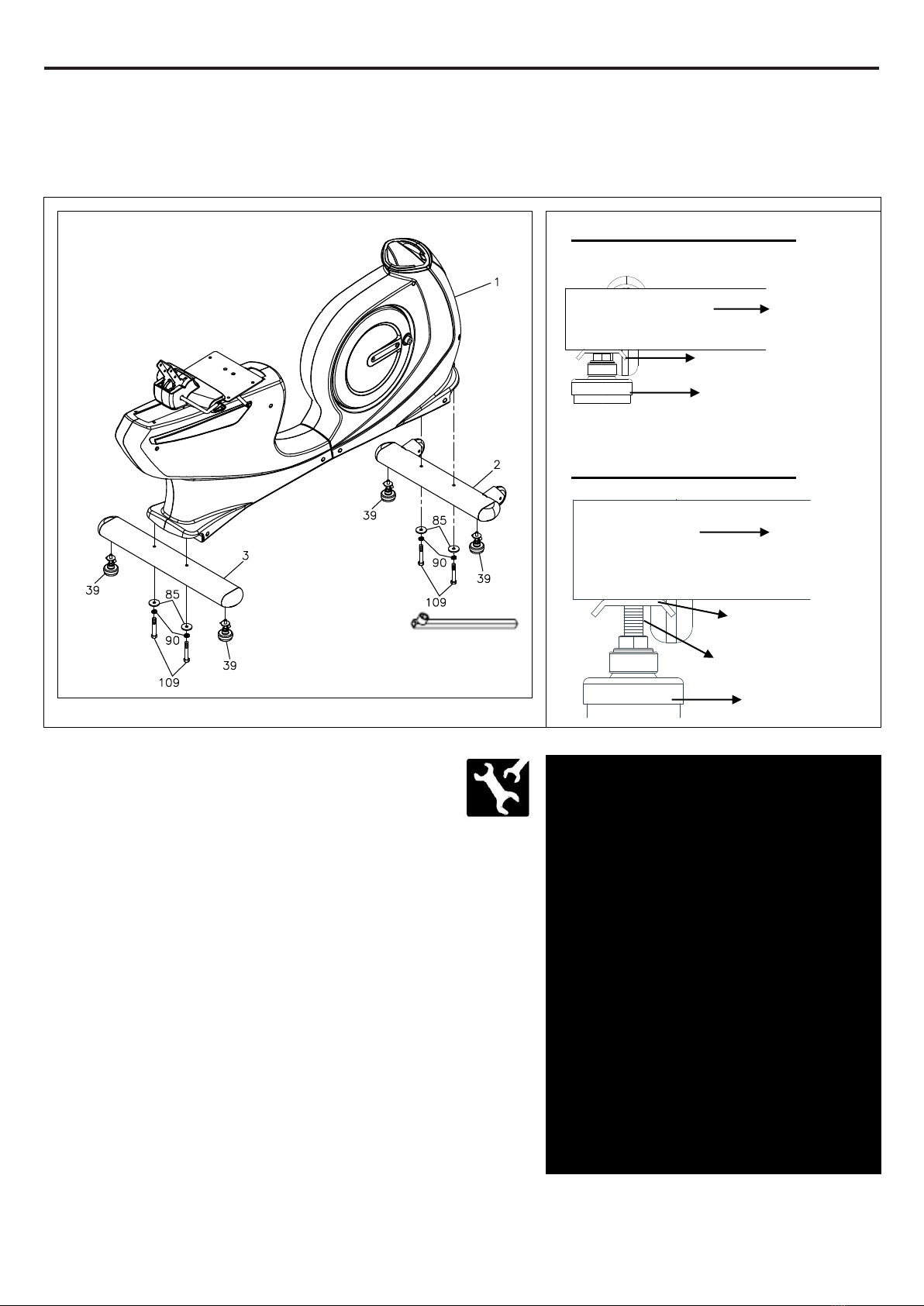
STEP 1
Attach the Leveler (39) to the Front
Stabilizer (2) and the Rear Stabilizer (3.)
Be sure to tighten the Leveler (39) securely against
the Stabilizers (2, 3) until screw lines are eliminated
as the drawing 1 shown.
STEP 2
Attach the Front Stabilizer (2) and the Rear Stabilizer (3)
onto the Main Frame (1) and secure with the Washer
(8x38x2.0t)(85,) the Lock Washer (M8)(90) and the Bolt,
Hex Head (M8xp1.25x65mm)(109) by using the socket
wrench as the main assembling drawing shows.
If the bike is not level, review the LEVELING NOTE on
the right side to level the Levelers (39.)
Detailed Lever- drawing 1
Detailed Lever- drawing 2
Adjustment Plate
Stabilizer
Leveler (39)
LEVELING: After placing the bike
in the intended location for use,
check the stability of the bike. If the
bike is not level, reviewing the
following direction:
Loosen the Leveler (39) to make
the Adjustment Plate become less
tight.
Adjust the Leveler (39) for leveling.
Tighten the Adjustment Plate
securely against the Stabilizer to
lock the Leveler (39) in stable
position as the drawing 2 shown.
Screw line
Stabilizer
Adjustment Plate
Leveler (39)
5
ASSEMBLE INSTRUCTIONS
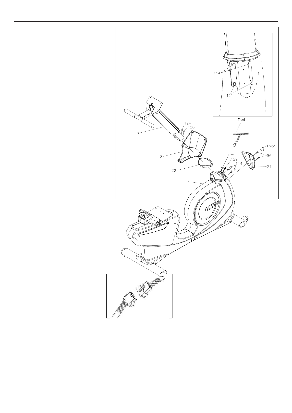
STEP 3
Slide the Console Bracket (18) and the
Upright Sleeve (22) onto the Upright
Post (8.)
Make sure the direction of the
Upright Post (8) is in the correct
direction as shown.
Be careful not to damage the
Middle Connection Wire (124)
and the Pulse Sensor Wire 2 (128)
while doing assembly Step 3 to 4.
STEP 4
a. Make sure 2 pcs Nylock Nut (M10)
(121) have already inserted into the
front of the Main Frame (1) as the
illustration shown on the top right
corner.
b. Insert the Upright Post (8) into the
Main Frame (1) and secure with the
Bolt, Hex Head (M10xp1.5x50mm)(114) by using the T-HEAD SOCKET WRENCH (17MM) as shown.
c. Secure 2 pcs Nylock Nut (M10) (121) which have already inserted into the front of the Main Frame (1)
STEP 5
a. Connect the Middle Connection Wire (124) to the Lower Connection Wire (125.)
b. Connect the Pulse Sensor Wire 2 (128) to the Pulse Sensor Wire 3 (129.)
Note the number of wire pin should be the same for both wires to connect with as the illustration shown
below.
c. Attach the Front Decorating Upright Cover (21) onto the front of the Main Frame (1) with the Screw,
Round Head (M5xp0.8x50mm)(96.)
d. Paste a Logo Sticker on the surface of the Front Decorating Upright Cover (21.)
A logo sticker is included in the hardware box.
e. Slide the Upright Sleeve (22) down to cover the open area of the Main Frame (1.)
6
ASSEMBLE INSTRUCTIONS
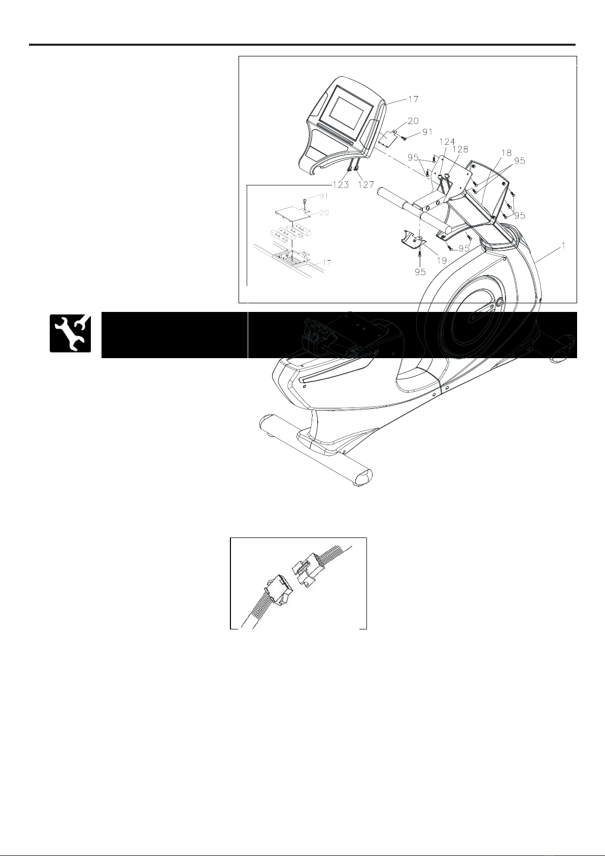
STEP 6
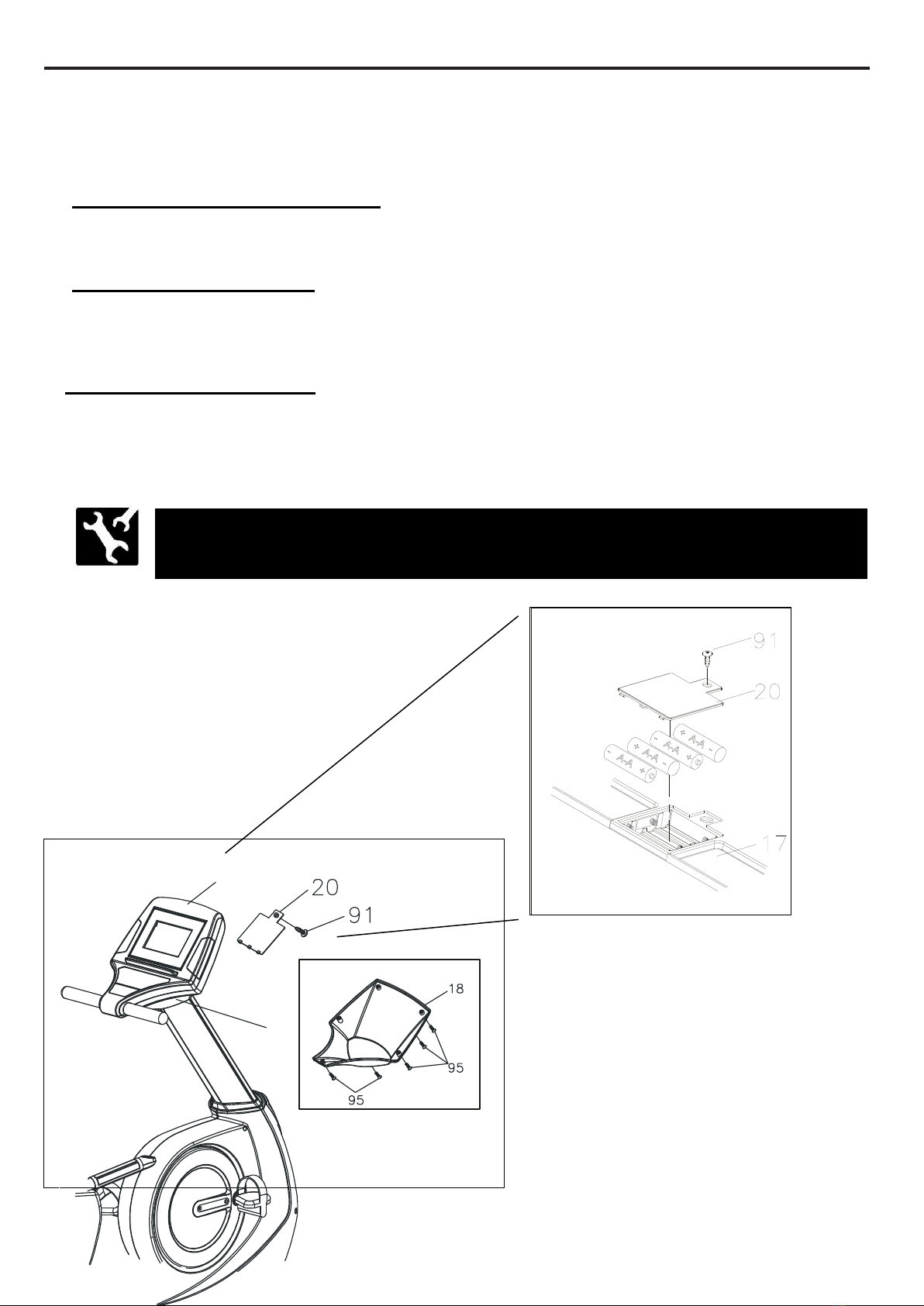
a. Loosen the Screw (M3x10mm)(91)
at the bottom on the console by
using the combination wrench to
open the Battery Door (20.)
b. The Console (17) operates with
FOUR AA rechargeable batteries,
four batteries included in the
hardware box.
The machine is suitable for
Nickel-Metal Hybrid/NI-MH
rechargeable batteries only.
c. Install rechargeable batteries into the console.
STEP 7
Attach the Battery Door (20) onto the back of the Console (17) with the Screw (M3x10mm)(91.)
STEP 8
a. Connect the Pulse Sensor Wire 1 (127) to the Pulse Sensor Wire 2 (128.)
Note the number of wire pin should be the same for both wires to connect with as the
illustration shown below.
b. Connect the Upper Connection Wire (123) to the Middle Connection Wire (124.)
Note the number of wire pin should be the same for both wires to connect with as the
illustration shown below.
STEP 9
Attach the Console (17) to the Main Frame (1) and secure with the Screw, Round
Head (M5xp0.8x15mm)(95.)
STEP 10
Attach the Console Lower Case (19) to the Console (17) and secure with the Screw, Round Head
(M5xp0.8x15mm)(95.)
STEP 11
Slide the Console Bracket (18) onto the Console (17) and secure with the Screw, Round
Head (M5xp0.8x15mm)(95.)
NOTE: To prevent from any damages, general batteries and other type of
batteries are not allowed.
7
ASSEMBLE INSTRUCTIONS
STEP 12
a. Press the Square Plug (30x60mm)(37)
into the Back Cushion Frame (6.)
b. To prevent from missing the bolts and
nuts, 4 pcs Lock Washer (M8) (90)
and 4 pcs Bolt, Button Head
(M8xp1.25x20mm) (102) are attached
on the Back Cushion Frame (6.)
c. Loosen the 4 pcs Lock Washer (M8)
(90) and 4 pcs Bolt, Button Head
(M8xp1.25x20mm) (102) at both sides
of the Back Cushion Frame (6.)
d. Follow the direction of the drawing line.
Insert the Back Cushion Frame (6)
onto the Back Cushion Adjustment
Bracket (52) and secure with 4 pcs
Lock Washer (M8) (90) and 4 pcs
Bolt, Button Head (M8xp1.25x20mm)
(102.)
STEP 13
To prevent from missing the bolts and
nuts, 4 pcs Bolt, Button Head (M8xp1.25x20mm) (102) is attached to the back of the Back Cushion
(24). Remove the 4 pcs Bolt, Button Head (M8xp1.25x20mm) (102) from the back of the Back
Cushion (24).
Attach the Back Cushion (24) onto the Back Cushion Frame (6) and secure with the Bolt, Button
Head (M8xp1.25x20mm) (102). Attach the Back Cushion Cover (23) onto the Back Cushion (24)
and secure with the Bolt, Round Head (M6×p1.0×15mm) (98.)
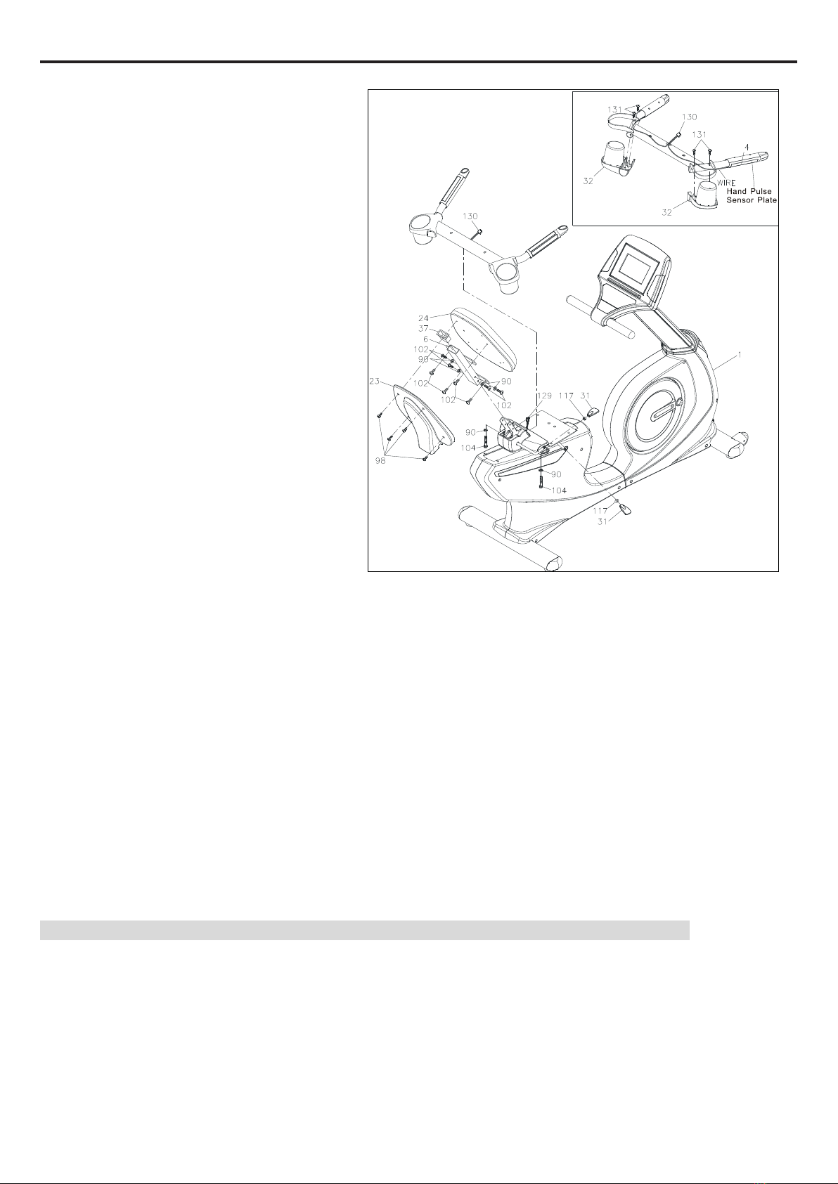
STEP 14
To prevent from missing the bolts and nuts, 2 pcs Nut (M8) (117) have already inserted into the Seat
Adjustment Lever (57). Thread 2 pcs Adjustment Bar (31) onto the Seat Adjustment Lever (57).
STEP 15
Refer to the insert drawing. Turn the Seat Handlebar(4) to have the Hand Pulse Sensor Plate
downward. Attach the Accessory Tray (32) onto the Seat Handlebar (4) and secure with 4pcs
Screw (M4x10mm) (131).
NOTE: Do not damage the Pulse Sensor Wire 4 (130) while securing Screws (131)
STEP 16
Follow the direction of the drawing line. Place the Seat Handlebar (4) onto the Main Frame (1) and
secure with the Lock Washer (M8) (90) and the Bolt, Socket Head (M8xp1.25x50mm) (104.)
STEP 17
Connect the Pulse Sensor Wire 4 (130) to the Pulse Sensor Wire 3 (129.)
8
ASSEMBLE INSTRUCTIONS
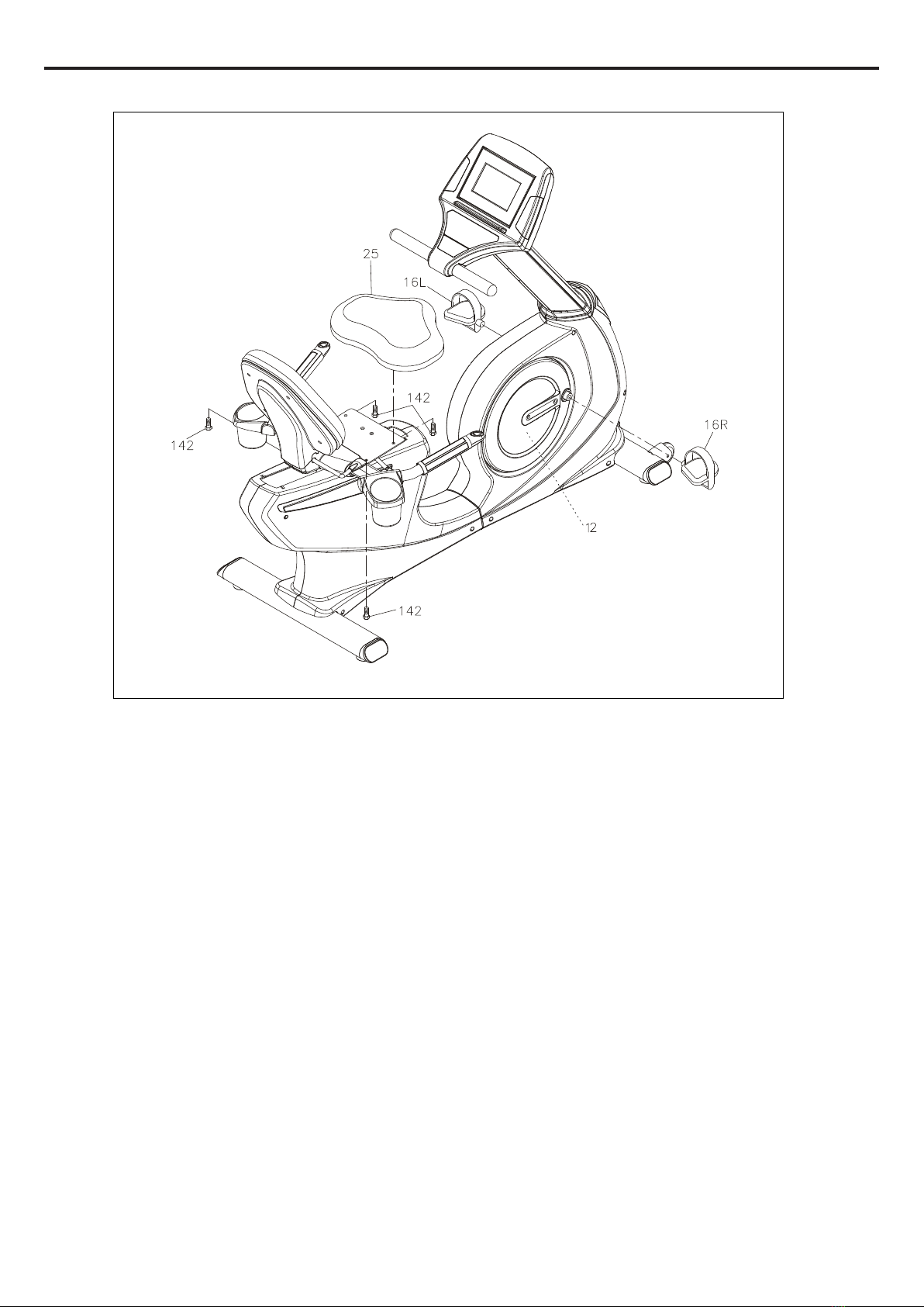
STEP 18
a. Note the Bolt, Hex Head (M8xp1.25x20mm) (142) have already inserted into the Seat (25.)
b. Loosen the Bolt, Hex Head (M8xp1.25x20mm) (142) at the bottom on the Seat (25.)
c. Attach the Seat (25) onto the Seat Frame (7) and secure with the Bolt t, Hex Head
(M8xp1.25x20mm) (142.)
STEP 19
Tread the Right Pedal (16) clockwise into the Right Crank located inside the Right Crank Cover (12)
as shown. Tighten the pedal securely. Repeat the same procedure to thread and tighten the Left
Pedal (15) counter-clockwise into the Left Crank as shown.
9
OPERATIONAL INSTRUCTIONS
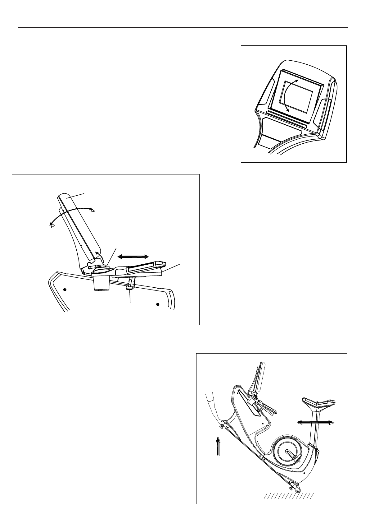
A. CONSOLE ANGLE ADJUSTMENT
To get the best angle, user could press the area A or B with the
personal need.
B. BACK CUSHION ADJUSTMENT
To adjust the most suitable angle, pull
the Back Cushion Adjustment Bar
upward while lying on the cushion.
Release the Back Cushion
Adjustment Bar and hear the “click”
sound to secure the desired angle of
the back cushion.
C. SEAT ADJUSTMENT
To adjust the most suitable position, pull
the Seat Adjustment Bar upward to
move the seat forward and backward.
Once adjusting to the most suitable
position, release the Seat Adjustment Bar until hearing “click”sound.
D. HOW TO TOW THE MODEL SAFELY
Hold the Rear Stabilizer (3) up with two hands and
tow the recumbent bike to the desired place
carefully.
Make sure the floor is level while towing the
bike.
Back Cushion
Seat Adjustment Bar
Seat
Back Cushion
Adjustment Bar
A
B
10
OPERATIONAL INSTRUCTION
HOW TO INSTALL AND REPLACE BATTERIES:
a. Take off the Console Bracket (18):
Loosen the Screw, Round Head (M5xp0.8x15mm)(95) at the bottom on the Console Bracket
(18.)
b. Open the Battery Door (20):
Loosen the Screw (M3x10mm)(91)at the bottom on the Console (17) by using the combination
wrench to open the Battery Door (20.)
c. Install and replace batteries:
The Console (17) operates with four AA rechargeable batteries, four batteries included into the
hardware box.
The machine is suitable for Nickel-Metal Hybrid/NI-MH rechargeable batteries only.
NOTE: To prevent from any damages, general batteries and other type of
batteries are not allowed.
18
17
11
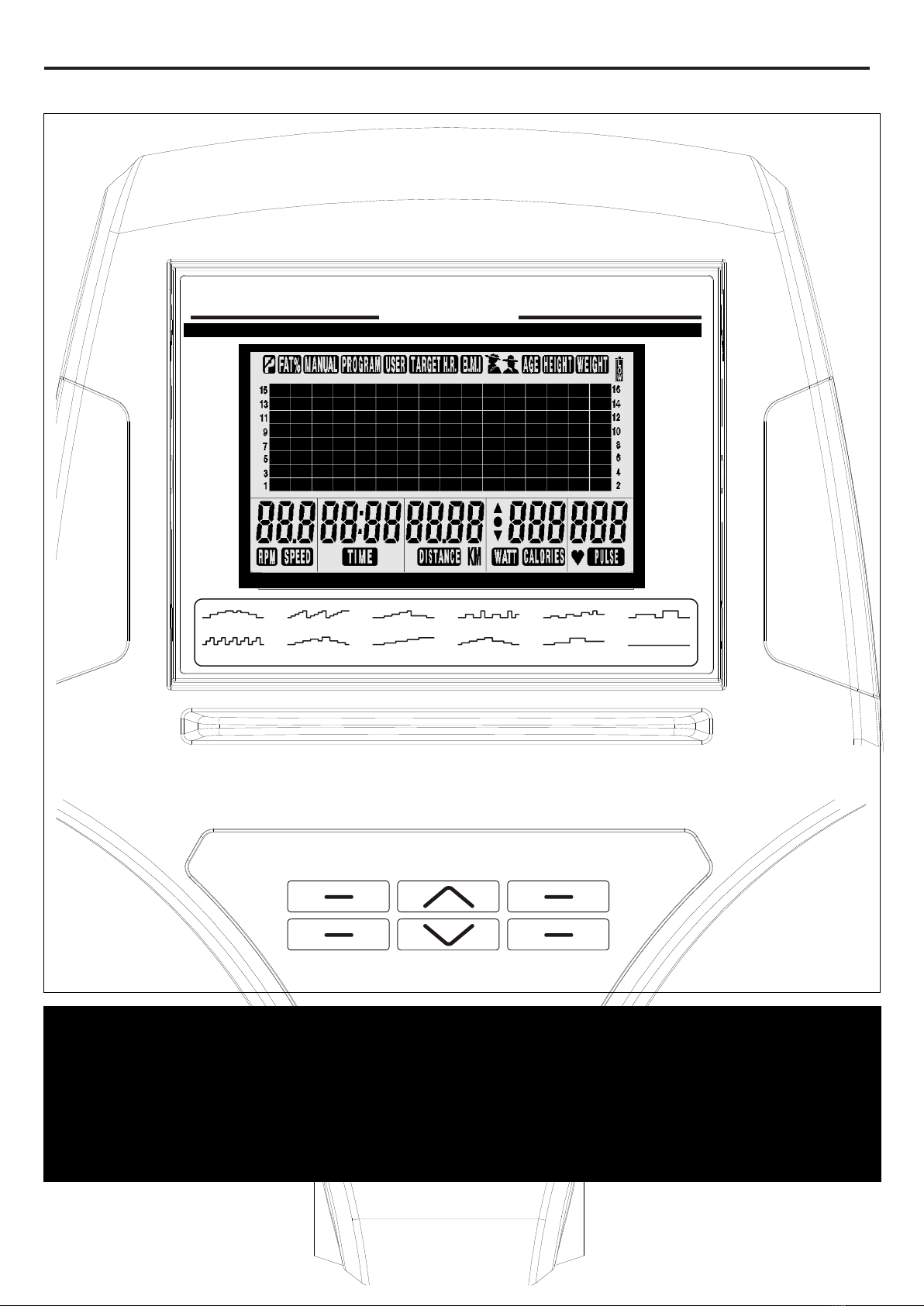
CONSOLE OVERVIEW
PROGRAM
MODE
START / PAUSE
QUICK START
RESET
CLEAR
ENTER
U P
DOWN
P1 P3 P5 P7 P9 P11
P2 P4 P6 P8 P10 P12
55%HRC
75%HRC
90%HRC
T HR
arget
Manual
User
The console display may vary slightly from the actual console display, the above console
overview is for reference only
The console has metric and imperial system difference due to the usage of the different
countries - Distance: 0.0~99.9 Km/Mile
12
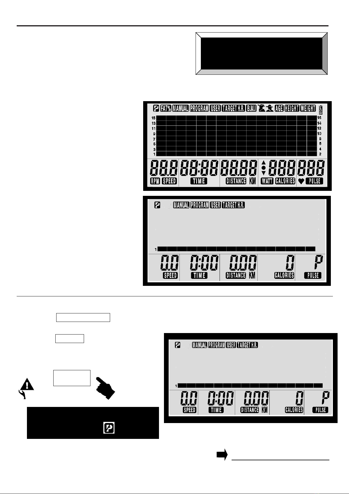
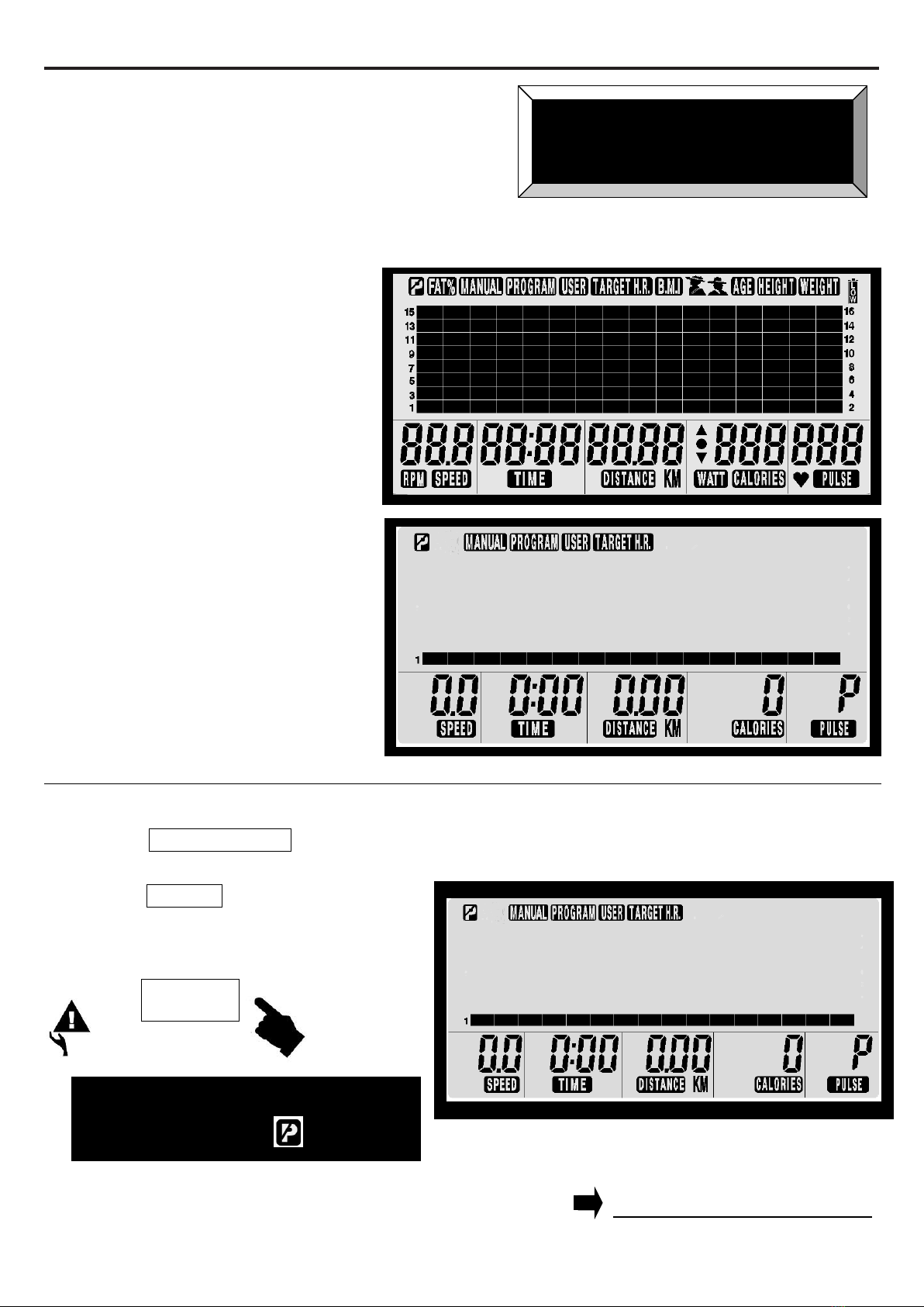
COMPUTER OPERATION
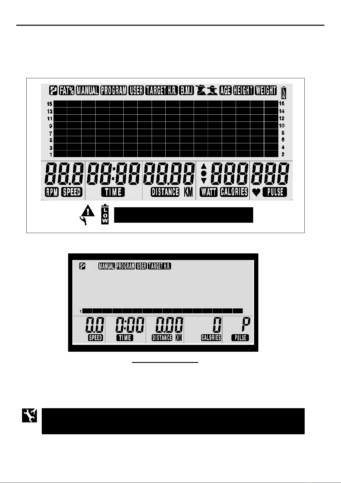
POWER ON:
a. Pedaling to activate the console.
b. The activated LCD console lights up along with a long beep sound. LCD diagram appears as below:
c. Enter into the initial setting mode after around two seconds as below:
POWER OFF:
The console would automatically shut off after 30 seconds of inactivity.
NOTE: the console would shut down any seconds if rechargeable batteries
run out of power.
NOTE: Low battery warning signal
Initial Setting Mode
13
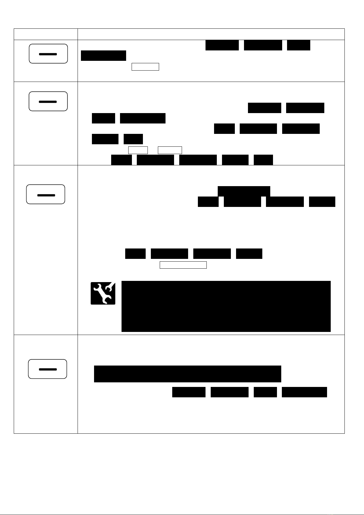
FUNCTION BUTTONS:
Button Name
Function Description
Press the button to select the desired mode –“MANUAL”, “PROGRAM”, “USER”,
“TARGET H.R.”.
Press the “ENTER”to confirm and enter the function value setting.
**The button is equipped with two operating methods**
a. Press the button to confirm and enter the selected mode (“MANUAL”, “PROGRAM”,
“USER”, “TARGET H.R.”.)
b. Press to select the function value displays of “TIME”, “DISTANCE”, “CALORIES”,
“PULSE”, “AGE”.
Use the “UP”or “DOWN”button to increase or decrease the desired function values
of “TIME”, “DISTANCE”, “CALORIES”, “PULSE”, “AGE”.
**The button is equipped with three operating methods**
a. QUICK START: Press the button to enter into “MANUAL MODE”immediately without
selecting the function value displays of “TIME”, “DISTANCE”, “CALORIES”, “PULSE”.
b. START/PAUSE button:
1. Press to start a workout.
2. Press to pause the program.
The console would display the current function values of workload level,
“TIME”, “DISTANCE”, “CALORIES”, “PULSE”.
3. User can press the “START/PAUSE”button again to continue to run the current
program.
**The button is equipped with two operating methods**
a. ZEROING FUNCTION: Press the button to reset each function value to zero during setting.
b. CHANGE SELECTED MODE- “MANUAL”, “PROGRAM”, “USER”, “TARGET H.R.”:
Under PAUSE MODE, hold the button for FOUR SECONDS to enter into the initial
setting mode. (Only operating under PAUSE MODE)
ENTER
RESET
The RESET function only operates under PAUSE MODE.
NOTE: All of the function values of “TIME”, “DISTANCE”,
“CALORIES”, “PULSE”in the memory would turn to initial function
values the console was set up after turning off or switching to
another mode (“MANUAL”, “PROGRAM”, “USER”, “TARGET H.R.”) .
PROGRAM
MODE
START/PAUSE
QUICK START
CLEAR
14
COMPUTER OPERATION
There are four ways to enter into MANUAL
MODE as below:
1. POWER OFF STATUS (LCD diagram disappear on LCD window):
a. Pedaling to activate the console.
b. The activated LCD console lights up
along with a long beep sound. LCD
diagram appears as shown on right
side:
c. Enter into the initial setting mode
after around two seconds as shown
on right side:
2. RESTART FUNCTION:
a. Press the “START/PAUSE”button to pause the current program.
a. Hold the “RESET”button for FOUR
SECONDS to enter into the initial setting
mode as illustration shown on the right.
c. Skip to Step B. of NORMAL OPERATION on the next page to continue the operation.
UNDER MANUAL MODE
RESET
The RESET function only operates
under PAUSE MODE .
CONTINUE TO THE NEXT PAGE
15
COMPUTER OPERATION
3. QUICK START:
a. “START/PAUSE”button: Press the “START/PAUSE”
button directly to start a
workout under “MANUAL MODE”without any setting.
b. Skip to Step C. of NORMAL OPERATION to select the function value of . “TIME”, “DISTANCE”,
“CALORIES”, “PULSE”
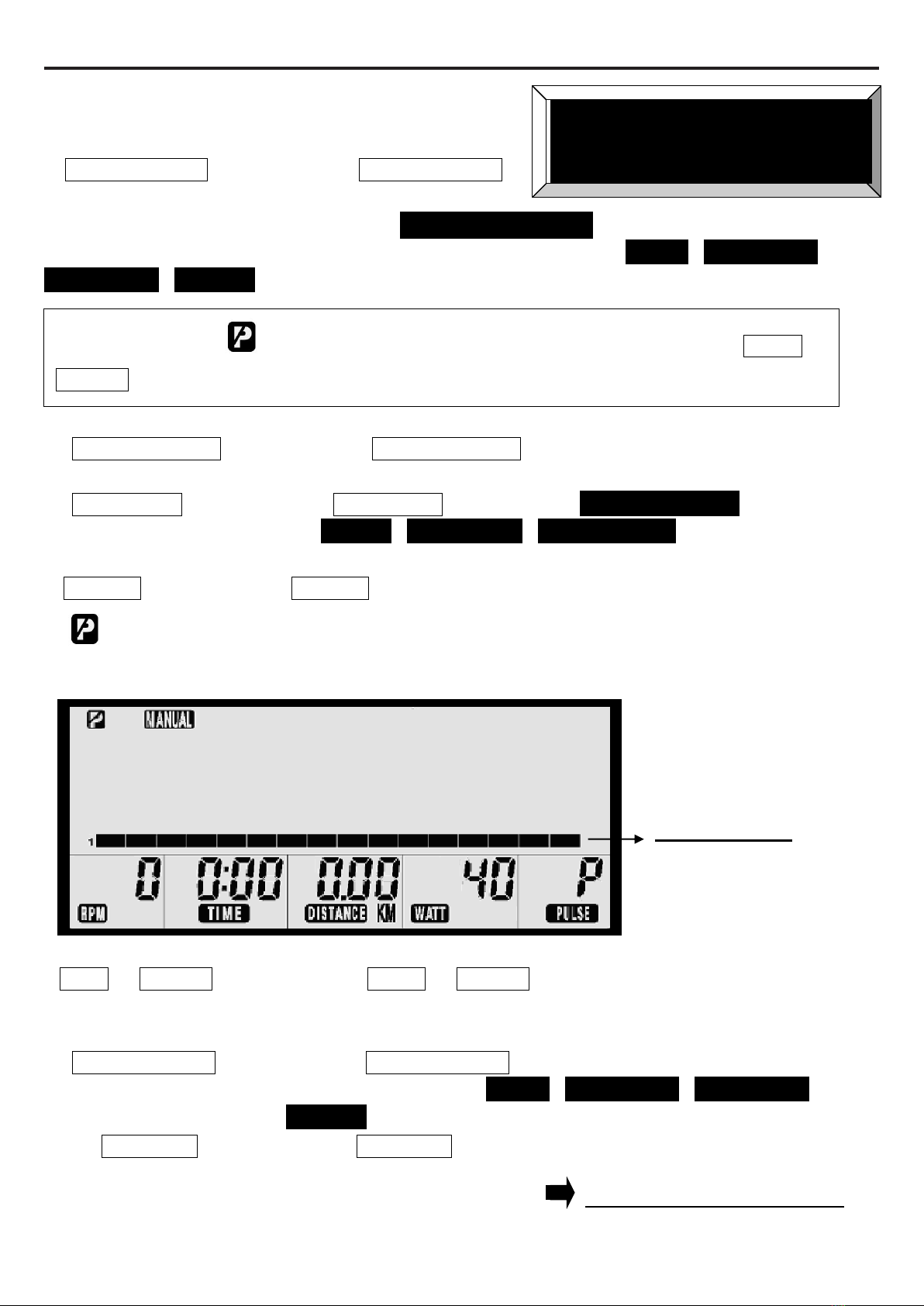
4. NORMAL OPERATION:
a. ““START/PAUSE”button: Press the “START/ PAUSE”button to pause the current program.
b. “PROGRAM”button: Press the “PROGRAM”button to select “MANUAL MODE”while in other
mode ( “USER”, “PROGRAM”, “TARGET H.R.”)
c. “ENTER”button: Press the “ENTER”button for confirming and entering the function value setting.
d. “PAUSE MODE”single will flash on LCD window for setting.
e. LCD window then display flashing “workload level”as shown.
f. “UP”or “DOWN”button: Press the “UP”or “DOWN”button to increase or decrease the
workload level (1~16 levels, 2 levels increment)
g. “START/PAUSE”button: Press the “START/PAUSE”button to start a workout directly without
setting function values ( “TIME”, “DISTANCE”, “CALORIES”,
“PULSE”.)
Or “ENTER”button: Press the “ENTER”button to continue to select other function values to
adjust the user’s workout.
Workload Level
CONTINUE TO THE NEXT PAGE
Under both PAUSE or START mode, workload level can be adjusted with the “UP”or
“DOWN”button.
UNDER MANUAL MODE
16
COMPUTER OPERATION
h. After pressing the “ENTER”button, the flashing “TIME”will appear on the LCD window.
i. “UP”or “DOWN”button: Press the “UP”or “DOWN”button to the program time as desire.
j. “START/PAUSE”button: To start a workout, press the “START/PAUSE”button .
NOTE: The console will cycle through the functions as follow and allow users to set
the function values.
TIME (01:00 to 99:00; 1minute increment) DISTANCE (0.1 to 99.9km; 0.1km
increment )CALORIES (10 to 990 Kcal; 10 Kcal Increment PULSE (70 to 240
BPM; 1BPM increment)
Press the “ENTER”button to confirm the function value and enter the next
function value setting.
Press the “UP”or “DOWN”button to select the value of the function
( “TIME”, “DISTANCE”, “CALORIES”, “PULSE”.)
To reset the function value to zero, press the “RESET button.
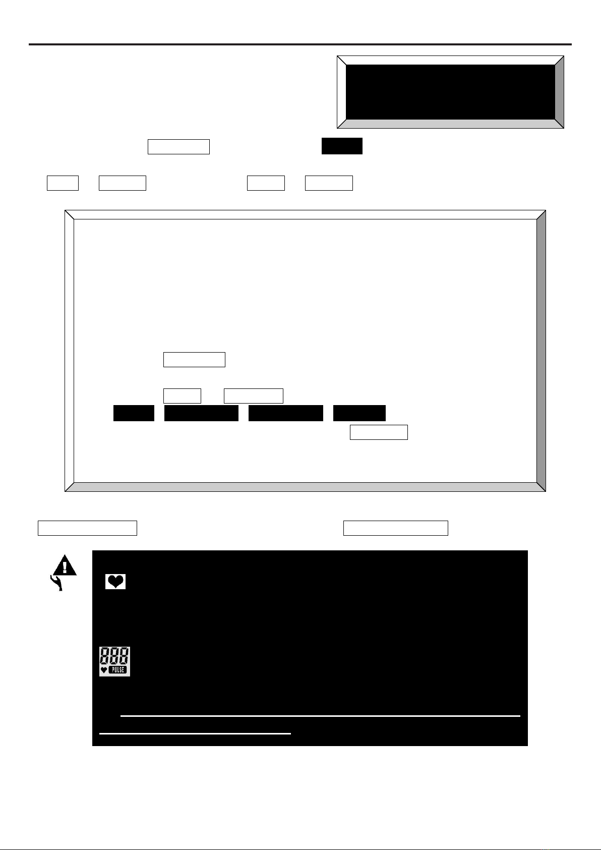
UNDER MANUAL MODE
a. WITHOUT PULSE VALUE:
“ ” flashing symbol will appear when detecting your pulse.
b. THE WARNING BEEP SOUND EMIT CONSTANTLY DURING
WORKOUT:
If your pulse is greater than the SELECTED PULSE VALUE
during workout, the short warning beep sound will constantly emit.
Please note that this is a warning for you to slow down or to
decrease the workload level.
17
COMPUTER OPERATION
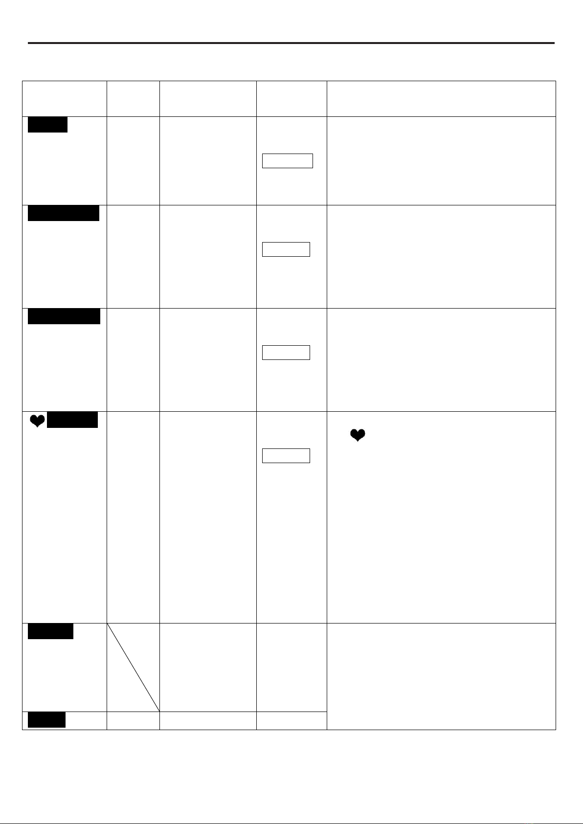
OVERVIEW SETTING VALUES:
Display
Readout
Display
range
Storage
Zeroing
Description and small tip
“TIME”
0:00 to
99:00
Yes
(During a
workout. The
selected value
will turn to zero
after turning off)
Yes
(Use
“RESET”
button)
1. Time will count up to 99:00 and cycle
run the program profile without setting.
2. Time will count down to 0 depends on
desired time value users set up. Two
short beep sound for warning the
selected value reach to zero.
“DISTANCE”
0.0 to
99.9km
Yes
(During a
workout. The
selected value
will turn to zero
after turning off)
Yes
(Use
“RESET”
button)
1. Distance will count up to 99:90km and
cycle run the program profile without
setting.
2. Distance will count down to 0 depends
on desired distance value users set up.
Two short beep sound for warning
selected value reach to zero..
“CALORIES”
10 to
990
Kcal
Yes
(During a
workout. The
selected value
will turn to zero
after turning off)
Yes
(Use
“RESET”
button)
1. Calories will count up to 990 Kcal and
cycle run the program profile without
setting.
2. Calories will count down to 10 depends
on desired calories value users set up.
Two short beep sound for warning
selected value reach to zero..
“PULSE”
70 to
240
BPM
Yes
(During a
workout. The
selected value
will turn to zero
after turning off))
Yes
(Use
“RESET”
button)
1. CONSOLE WITHOUT PULSE VALUE:
“ ” flashing symbol will appear when
detecting your pulse.
2. WARNING BEEP SOUND EMIT
CONSTANTLY FROM A CONSOLE:
If your pulse is greater than
the SELECTED PULSE VALUE
during workout, the short warning beep
sound will constantly emit.
Please note that this is a warning for
you to slow down or decrease the
workload level.
“WATT”
Yes
(During a
workout. The
selected value
will turn to zero
after turning off)
Yes
(Use
RESET
button)
EACH 6 SECONDS
WATT/ CALORIES, RPM/ SPEED
WOULD SWITCH DISPLY ON LCD
WINDOW
“RPM”
0 to 250
No
Yes (Auto)
18
COMPUTER OPERATION
There are three ways to enter into PROGRAM
MODE as below:
1. POWER OFF STATUS (LCD diagram disappear on LCD window):
a. Pedaling to activate the console.
b. The activated LCD console lights up
along with a long beep sound. LCD
diagram appears as shown on right
side:
c. Enter into the initial setting mode
after around two seconds as shown
on right side:
2. RESTART FUNCTION:
a. Press the “START/PAUSE”button to pause the current program.
b. Hold the “RESET”button for FOUR
SECONDS to enter into the initial setting
mode as illustration shown on the right.
c. Skip to Step B. of NORMAL OPERATION on the next page to continue the operation.
UNDER PROGRAM MODE
RESET
The RESET function only operates
under PAUSE MODE .
CONTINUE TO THE NEXT PAGE
19
COMPUTER OPERATION
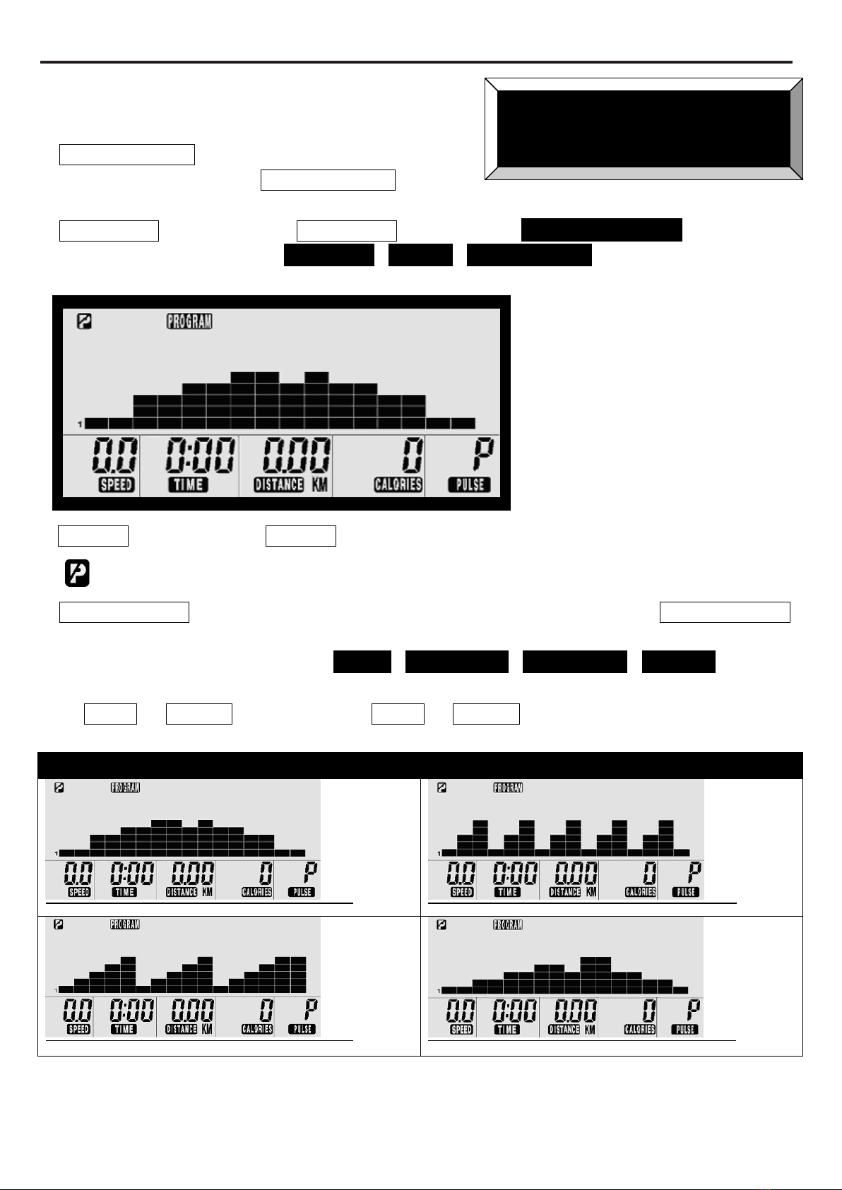
3. NORMAL OPERATION:
a. ““START/PAUSE”button: Press the
“START/ PAUSE”button
to pause the current program.
b. “PROGRAM”button: Press the “PROGRAM”button to select “PROGRAM MODE”while in other
mode ( “MANUAL”, “USER”, “TARGET H.R.”)
c. “ENTER”button: Press the “ENTER”button for confirming and entering the function value setting.
d. “PAUSE MODE”single will appear on LCD window for setting.
e. “START/PAUSE”button: After flashing “P1”appears on LCD window, press the “START/PAUSE”
button to start a workout directly without setting function values (Profile
(P1~P12), “TIME”, “DISTANCE”, “CALORIES”, “PULSE”.)
Or “UP”or “DOWN”button: press the “UP”or “DOWN”button to directly select the desired
profile (P1 to P12) as shown.
P1 to P12 are preset automatic programs. The profiles are shown on LCD window.
P1
P2
P3
P4
UNDER PROGRAM MODE
Table of contents
Other STI FITNESS Exercise Bike manuals

Popular Exercise Bike manuals by other brands


BH FITNESS
BH FITNESS FDR20 Instructions for assembly and use

NordicTrack
NordicTrack Gx5.1 Bike Kullanıcı kılavuzu

Vision Fitness
Vision Fitness R2200HRT owner's guide

Nautilus
Nautilus R628 Assembly manual / owner's manual
ICON Health & Fitness
ICON Health & Fitness Pro-Form 225 CSX user manual

Impex
Impex MARCY ME-709 owner's manual