STI AP5102 Series User manual

SERIES AP5102
DIN-Rail Conditioner for LVDTs
TECHNICAL MANUAL
Copyright © Stellar Technology Incorporated • All Rights Reserved
237 Commerce Drive • Amherst, NY 14228 • USA
Tel:
716.250.1900 •
Fax:
716.250.1909
Email:
info@stellartech.com
ISO 9001:2000

INDEX
1. INTRODUCTION ........................................................................................................ 2
2. INSTALLATION INSTRUCTIONS .............................................................................. 3
2.1 EMC Requirements .................................................................................................. 3
2.2 Unit Mounting ........................................................................................................... 3
2.3 Connections General ................................................................................................ 4
2.4 Internal Controls ....................................................................................................... 5
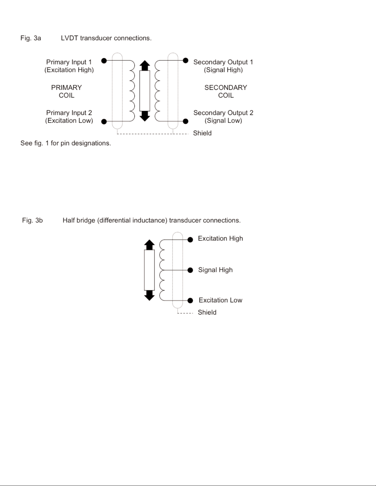
2.5 Transducer connections (LVDT and half bridge) ...................................................... 6
3. CONTROLS ................................................................................................................ 6
3.1 Voltage/Current Output ............................................................................................. 6
3.2 Coarse Gain Selection ............................................................................................. 6
3.3 Fine Gain (On front panel, labelled GAIN) ............................................................... 6
3.4 Coarse Zero ............................................................................................................. 6
3.5 Zero Input .................................................................................................................7
3.6 Fine Zero (On front panel, labelled ZERO) .............................................................. 7
3.7 Over-Range Indicator ............................................................................................... 7
3.8 Excitation Voltage ..................................................................................................... 7
3.9 Excitation Frequency ................................................................................................ 7
3.10 Master/Slave ........................................................................................................... 7
4.0 SETTING UP PROCEDURES ................................................................................. 8
4.1 LVDT & Half Bridge (Differential Inductance) Transducers ...................................... 8
5. SPECIFICATION ........................................................................................................ 9
6. WARRANTY ...............................................................................................................10
1. INTRODUCTION
The AP5102 is a single channel signal-conditioning unit for use with transducers requiring
AC excitation and synchronous demodulation, producing a DC output voltage or current.
The AP5102 incorporates a DC-DC converter ensuring that the output of the unit is
electrically isolated from the supply.
Units may be master-slaved in systems where carrier frequency beating is a problem.
The unit is housed in a DIN-rail mounting thermoplastic case with recessed screw-clamp
terminals for all connections and 25-turn front-panel-accessible span and zero
adjustments.
All other controls are internal including coarse gain and zero switches, a zero input switch
and jumper links for master/slave setting and excitation frequency setting.
The unit is suitable for use with the complete range of STI LVDT transducers.
2

2. INSTALLATION INSTRUCTIONS
2.1 EMC Requirements
For optimum EMC performance use shielded multi-core cables for connection to this
instrument; the cable shield may be terminated by means of a short "pig-tail" and
connected to the terminals marked:
(a) Pin 5 – Transducer cable
(b) Pin 15 – Supply/Output cable
The DIN-rail to which the unit is attached should be grounded.
The screw clamp terminals can accept either solid or stranded wire sizes from 0.2 mm
(24 AWG) to 2.5 mm (12 AWG).
NOTES:
1. Cable shields to be grounded at only one end - the AP5102 end, although grounding
at both ends may reduce the effects of high frequency EMI.
2. When the AP5102 is a small part of a large electrical installation, ensure the cables
to and from the AP5102 are segregated from electrically noisy cables.
3. Ensure cables to and from the AP5102 are routed away from any obviously powerful
sources of electrical noise, e.g. electric motor, relays, solenoids.
4. ESD precautions should be used when working on the instrument with the lid
removed. The user should ensure he is "grounded" by use of an grounded wrist strap
or at least touching ground before touching any component including wires, terminals
or switches.
5. The transducer body should be grounded. Some transducers such as LVDTs, load
cells, etc. without an internal body-to-shield connection, require a separate ground.
This should preferably be connected to the instrument shield terminal or as near
(electrically) as possible to this point.
2.2 Unit Mounting
The AP5102 housing is a standard DIN rail enclosure which can clip directly to a 35 mm
top hat rail. The units can be mounted side by side if in an ambient temperature up to
105°F. Above this temperature, a gap of 15 mm should be left in between each unit.
3

2.3 Connections General
2.4 Internal Controls
To access internal controls the front part of the AP5102 case needs to be removed. To do
this, use a small screw driver to gently press in the clips behind terminal 1-4 and 13-16. At
the same time pull forward the front of the case. The front of the case and pcb assembly
should now slide forward.
It will usually only be necessary to make changes to Gain and Zero controls.
To put case back together, gently slide pcb assembly into case guide slots. Ensure pcb
ground pad CG1 is lined up with the ground clip inside the case, and push back until the front
of the case clicks back into place.
4

2.5 Transducer connections
Most STI LVDT transducers also have a BLACK wire. This is not required with the
AP5102 amplifier and should be insulated and left unconnected.
If the above configuration does not give the required output phase (i.e. the output rises
for outward transducer movement instead of falling); reverse signal high and signal low
connections
In addition to these connections, it is necessary to add two bridge completion resistors
to compensate for the fact that the transducer is only half bridge. For STI transducers,
the resistors should be 1k Ohms, high stability. These should be mounted in R11 and
R12 locations, as shown in Fig. 2.
If when connected, the phase of the amplifier output is not as required (for example, an
inward moving armature causes a rising amplifier output when a falling output is
required) then reversing the excitation high and excitation low wires will correct this.
5

3. CONTROLS
(For locations, see Figure 2)
3.1 Voltage/Current Output
Voltage output is available between pins 9 & 10 (common). Current output is available
between pins 12 and 11 (common). Pins 10 and 11 are internally connected.
3.2 Coarse Gain Selection
Typically, transducer manufacturers' data sheets or calibration certificates will give a figure
allowing the full-scale output to be calculated. Possible formats for this are as follows; the
examples assume a transducer range of ±50mm.
The following table shows the band of transducer full-scale output voltages appropriate to
each of the 8 Gain Range Settings. For example, a transducer with a full-scale output of
2.3V would be correctly set as gain range 3 for a ±5V DC output..
An 4-way toggle switch, SW1, sets the overall gain in the ranges shown below:
3.3 Fine Gain (On front panel, labeled GAIN)
A screwdriver-adjusted, 25-turn potentiometer providing a 4:1 adjustment of gain,
interpolating between the ranges set by the GAIN RANGE switch.
3.4 Coarse Zero
A 5-way toggle switch, SW2, (toggle 6 – see section 3.5) provides output zero shifts of
about 1V per step (with Fine Gain at minimum – up to 4V at maximum). When used with
FINE ZERO will suppress any output (up to 5V) to zero. All toggles OFF is normal, ie no
suppression applied. Switching toggle 1 ON with toggles 3, 4 or 5 will suppress positive
outputs. Switching toggle 2 ON with toggles 3, 4 or 5 will suppress negative outputs. The
suppression increases when toggles 3, 4 or 5 are switched ON.
6

3.5 Zero Input
SW2 toggle 6 which, when switched to ON, zero’s the signal, input voltage to the amplifier
irrespective of transducer position. This enables a true amplifier zero to be realised.
3.6 Fine Zero (On front panel, labelled ZERO)
A screwdriver-adjusted, 25-turn potentiometer allowing adjustment of output zero by ±1v to
±4v depending on Fine Gain setting. Used with 3.3 will provide up to 100% suppression.
3.7 Over-Range Indicator
A red lamp that indicates when the demodulator input exceeds the linear range.
3.8 Excitation Voltage
Units are normally supplied with 1V excitation. This can be changed to 3V by changing J3 to B-C.
3.9 Excitation Frequency
3.10 Master/Slave
The unit may be configured as a master oscillator or slave oscillator by the setting of J2.
For Master oscillator (Factory Default) link J2 B-C See Fig 2 for the
For Slave units link J2 A-D location of J2
Link terminal 6 on the MASTER unit with terminal 7 on the SLAVES and link terminal 8 on
all units as shown below:
7

4.0 SETTING UP PROCEDURES
4.1 LVDT & Half Bridge (Differential Inductance) Transducers
4.1.1 Determine the transducer full scale output from the manufacturer's data sheet and
set the Coarse Gain control as shown in Sections 3.
4.1.2 Connect the transducer to the 4-way connector as detailed in Section 2. Switch ON
power and allow a 15-minute warm-up period (for maximum accuracy).
4.1.3 Switch on the ZERO INPUT switch (SW2 toggle 6) and adjust the ZERO controls on
the AP5102 for either 0 volts or 12 mA output (depending on which output is being used).
Switch off the ZERO INPUT switch.
4.1.4 Adjust the transducer armature for either 0 volts or 12 mA output from the AP5102.
The FINE ZERO control may be used to obtain an absolute zero indication if the armature
adjustment is too coarse.
Now proceed with either 4.1.5 or 4.1.6 according to application.
4.1.5 Bipolar Operation (e.g. ±5V or 4-20mA)
(a) Move the transducer armature by a precise amount (e.g. 5mm for a LMS60X transducer)
and adjust the FINE GAIN control for the desired output, e.g. 5v, or 20mA.
(b) Relocate the transducer armature at the centre of the stroke and check that the
output is zero. Re-adjust the FINE ZERO control if necessary.
Repeat (a) and (b) for consistent results.
(c) Move the armature to the full-scale position in the opposite direction and check for
example -5v or 4mA output.
4.1.6 Unipolar Operation (e.g. 0 to 10V)
If it is required that the transducer be used over its entire working range in the one
direction, e.g. 0 to 10mm for a LMS60X transducer, then the zero controls are used to
"back-off" the signal equivalent to 5mm, then:-
(a) Set up as in 4.1.5, i.e. ±5V output for ±5mm using a LMS60X.
(b) Move the armature by exactly 5mm (for a LMS60X transducer) and then adjust the
ZERO controls to back off this signal to zero. Now move the armature back 10mm
and adjust the FINE GAIN control for the required output.
(c) Repeat (b) until consistent results are obtained. If, for any reason, the coarse gain
is changed, restart the whole procedure.
8

5. SPECIFICATION
Supply 9 to 36 V DC 250 mA max (Isolated from output)
Voltage Output ±10V into 2k ohm
Current Output 4-20mA into 100/550 ohm max.
Overload internally limited to 30mA max.
Oscillator Output 1V rms. at 5kHz standard. 25mA maximum.
3Vrms and 3 kHz also available.
Oscillator Temperature Coefficient 0.003%/°F typical
Demodulation Synchronous
Amplifier Gain X0.07 to X500 in 8 ranges with fine control interpolation
Zero Range ±5V minimum
Linearity 0.05% of full scale
Input Resistance 130k ohm differential
Zero Stability
Voltage Output 0.001% of FS typical/°F
Current Output 0.003% of FS typical/°F
Gain Stability
Voltage Output 0.003% of FS typical/°F
Current Output 0.05% of FS typical /°F
Bandwidth DC to 250Hz (flat)
Noise
Voltage Output 5mV RMS
Current Output 20 µA RMS typical
EMC Specification When subjected to radiated electro-magnetic energy (as
EN61000-4-3) an additional error can occur at certain
frequencies:
Field Strength Typical Maximum Error
10V/m 1.5%
3V/m 0.1%
Temperature Range +14°F to +140°F
Dimensions 4.51 x 0.89 x 3.90 inches
Weight 4.4 oz
Seals IP20 specification
9

10
237 Commerce Drive • Amherst, NY 14228 • USA
Tel:
716.250.1900 •
Fax:
716.250.1909
Part No. 234199C DCN 16523
Email:
info@stellartech.com
ISO 9001:2000
WARRANTY: Stellar Technology warrants that its product shall be free from defective workmanship
and/or material for a twelve month period from the date of shipment, provided that Stellar Technology’s
obligation hereunder shall be limited to correcting any defective material FOB our factory. No
allowance will be made for any expenses incurred for correcting any defective workmanship and/or
material without written consent by Stellar Technology. This warranty is in lieu of all other warranties
expressed or implied.
Table of contents
Popular Industrial Electrical manuals by other brands

Murata
Murata GQM22M5C2H101FB01 Series Reference sheet

Murata
Murata GRM022R60J102ME19 Series Reference sheet

Murata
Murata GRM319R71H472KA01 Series Reference sheet

Murata
Murata GRM0335C1E6R2DA01 Series Reference sheet

Hafele
Hafele Slido Classic Series manual

Murata
Murata GQM1875C2E3R0WB12 Series Reference sheet

Siemens
Siemens SIVACON 8PS BD2 Series installation instructions

Murata
Murata GRM0225C1E7R6WDAE Series Reference sheet

Murata
Murata GRM155R61A103KA01 Series Reference sheet

Intermatic
Intermatic InTouch CA3750 manual

Hainbuch
Hainbuch HYDROK installation manual

Murata
Murata GRM2167U1H103JA01 Series Reference sheet