STIENEN PL-9500 User manual

USER MANUAL
PL-9500 (-i) POULTRY COMPUTER
EN
© Stienen BE / PL-9500-G-EN02000
PL-9500
PL-9500-i

Shut down power before opening the poultry computer!
This poultry computer contains exposed live parts!
Only to be opened by authorized personnel!
WARNING
Although utmost care has been given to the quality of this equipment during the design and manufacturing stages,
technical malfunctions can never be ruled out. The user should provide for an adequate alarm system
and/or emergency provisions to prevent a technical failure of the equipment and peripheral facilities
leading to danger to persons, animals or property.
NOTE DOWN THE FOLLOWING IN CASE OF AN EMERGENCY
●Possible causes
●Circumstances in which the emergency occurred
●Date and software version number
●Installer settings
Please contact our Customer Service Department, if you have any questions. Be sure to have all necessary data at
hand. To ensure a speedy solution to the malfunction and to avoid any misunderstandings, it is advisable to note
down the cause and the circumstances in which the malfunction occurred before contacting us
(www.StienenBE.com).
No part of this document may be reproduced or transmitted in any form or by any means, electronic or
mechanical, for any purpose, without the express written permission of Stienen BE
Stienen BE accepts no liability for the contents of this manual and explicitly waives all implicit guarantees of
merchantability or fitness for a certain use. Stienen BE also reserves the right to improve or change this manual
without being under the obligation to inform any person or organisation of any such improvement or change.
Stienen BE cannot be held liable for any damage, loss or injury resulting from improper use or from use not in
accordance with the instructions in this manual.

Contents Page
OPERATION 5
Changing language 5
Login 5
Control keys 5
Led bar 6
Terminal number in-/outputs 7
MAIN MENU 8
Overview screen 9
MANAGEMENT 10
Animals 10
Animal weighing 10
Feeding 10
Counters 11
Hour counter 11
Min./Max. 11
Logging 11
CLIMATE 12
House 12
Main ventilation 12
Auxiliary ventilation 13
Heat exchanger 13
Inlet flaps 14
Heating 14
Cooling 15
Temperature controls 16
Miscellaneous 16
FEED 17
Feed weighing 17
Feed mixture 20
Per day 21
Per period 21
TIMERS 22
Master timer 22
Light timer (controlled light) 23
Dosage timer (water / feed / sequential timers) 24
Miscellaneous (on/off timers, nest box timer) 25
Time schedules 25
ALARMS 26
Alarm codes 27
SYSTEM 30
MAINTENANCE AND CHECK UP 31

If the software version of a module or peripheral device does not comply with the
requirements of the operating software, you have to perform a software update for the
module and/or peripheral device.
CLEANING HR-SENSOR, CO
2
SENSOR OR MEASURING FAN
WITH A HIGH-PRESSURE SPRAY GUN IS NOT ALLOWED
Remove the RH sensor and CO
2
sensor from the room and store them
somewhere safe before cleaning the room. Also screw the protection cap
onto the plug of the extension cables to prevent water from penetrating
into the plug. When connecting the sensor via a fixed socket outlet (FSO),
push on the flap of the fixed socket outlet until you hear it click (lock).
Application notes
Animal weighing
PL95IAW-N-ENxxxxx
Central exhaust
PL95ICE-N-ENxxxxx
Data communication between poultry computers
PL95IDC-N-ENxxxxx
Feed system
PL95IFS-N-ENxxxxx
General description
(ventilation controls, temperature control, heating, cooling, humidity)
PL95IGD-N-ENxxxxx
Heat exchanger
PL95IHE-N-ENxxxxx
Heating controls
PL95IHC-N-ENxxxxx
Manure belt
PL95IMB-N-ENxxxxx
Meteo control
PL95IMC-N-ENxxxxx
Remote control
PL95IRC-N-ENxxxxx
Timers
PL95ITC-N-ENxxxxx
Tunnel ventilation
PL95ITV-N-ENxxxxx
Ventilation control (cascade, interval, auxiliary etc.)
PL95IVC-N-ENxxxxx
Attachments
AQC-G-Table AQC-GS-B-ALxxxxx
PL-9200-POT PL-9200-POT-B-ALxxxxx
PL-9200-MOD PL-9200-MODULE-B-ALxxxxx
xxxxx = version number application note

Page 5 of 31
OPERATION
CHANGING LANGUAGE
Available languages:
ENG
NLD
DEU
FRA
RUS
POL
HUN
SPA
CES
TUR
CHN
JAP
Previous
Next
: select next language (see also “
System”, page 30).
: select previous language.
LOGIN
Touch : open login screen.
Touch : open numerical keypad.
Enter your login code and touch the key.
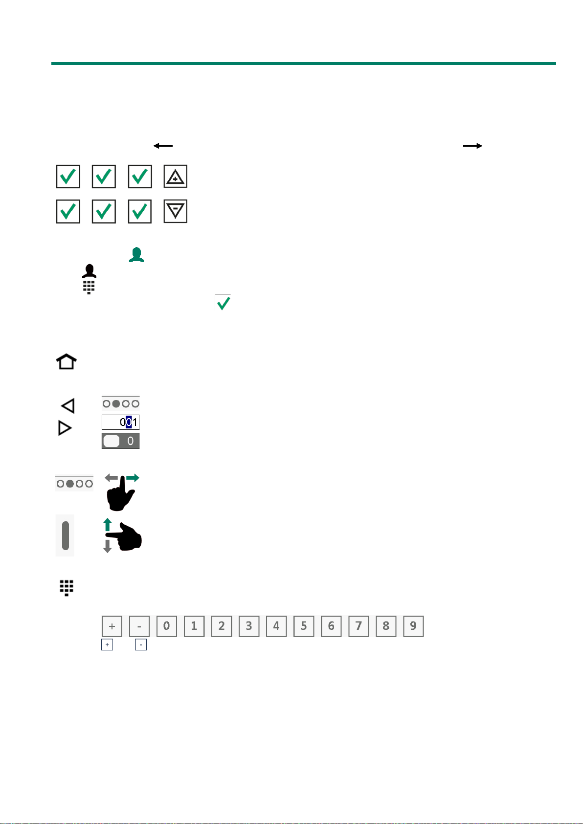
CONTROL KEYS
: return to the overview screen (HOME).
: select next/previous screen.
: select input position.
: select option.
: next/previous screen.
: scroll up/down (scroll bar on right side).
If this symbol lights up, touch the symbol to display one of the following virtual keyboards on the
screen.
Set the numerical value:
and : change the sign of a value.

Page 6 of 31
Alphanumeric:
and : select other characters.
: toggle between lower case letters and capitals.
: switch to digits and alternative characters.
: decrease/increase setting.
: select an option from a selection box.
: undo an option/selection in edit mode.
: confirm an option/selection in edit mode.
: add a breakpoint to/remove a breakpoint from a list (curve, timer).
: if a setting is followed by the “Link” symbol, use this link to jump to another screen. The “Link
back” symbol will then show in the right-hand top corner of the “follow-up screen”.
LED BAR
Blue
permanently lit:
Device not in
use
Green
permanently lit:
no alarm
Yellow
permanently lit:
alarm, alarm delay time
has not expired yet
Red
permanently lit:
alarm
blinks regularly:
main alarm off
blinks irregularly:
alarm switched off temporarily

Page 7 of 31
TERMINAL NUMBER IN-/OUTPUTS
The terminal number of an input/output consists of the module address, the type of input/output and a 2-digit
serial number.
Type in-/output
Letter
Serial number
Description
0-10V output
A
1-99
Analogue output with a range of 0-10V or 10-0V.
Relays output B 1-99
Relay contact output (this does not include: alarm relay,
pulse outputs etc.)
Digital output
C
1-99
Opto coupler output (Max. 35Vdc 30mA).
Open-/close control D 1-99
Open-/close control with position feedback signal.
This includes e.g. flaps with position feedback signal.
30-230Vac output
F
1-99
Analogue output with a range of 30-230Vac or 230-30Vac.
2-10V output G 1-99
Analogue output with a range of 2-10V with position
feedback signal. Among these are modules for controlling an
EGM-100CA or EGM-250CA
Air inlet flap
H
1-99
MCA flap, a wind compensated air inlet flap
Temperature sensor K 1-99
This includes all types of temperature sensor fitted with 10K
NTC resistor (N10B, BV10B etc.)
0-10V input L 1-99
Analogue input with a measuring range of 0-10V. To connect
measuring sensors such as RH, CO2, pressure etc.
Digital input
M
1-99
This includes measuring fans, counter contacts etc.
Meteo station N 1-99
Module on which a wind speed meter, wind direction and a
rain sensor can be connected to.
If the keyboard symbol lights up, touch the symbol to display one of the following virtual keyboards
on the screen.
Set input terminals
Set output terminals
and : decrease/increase setting.
MODULE SCREEN
Input/output already assigned.

Page 8 of 31
MAIN MENU
Animals
(mutations, reviews, entry data, growth curve,
lost)
Animal weighing
(settings, mutations, history, curve, alar
ms)
Feeding
(water/feed, fed, bulked)
Counters
(review, alarms, clear)
Hour counter
(heating, cooling, external)
Min./Max. values
(house, outside, sensors)
Logging
(heat exchanger)
House
(settings, growth curve, compensations, alarms)
Main ventilation
(sett
ings, options, growth curve, compensations, alarms)
Auxiliary ventilation
(settings, growth curve, compensations, alarms)
Heat exchanger
(settings, options, growth curve
, compensations, alarms)
Inlet flaps
(settings, options, growth curve, compensations, alarms)
Heating
(settings, growth curve, alarms)
Coolers
(settings, options, growth curve, compensations, alarms)
Temperature controls
(settings, alarms)
Miscellaneous
(humidification, grow
th curve, central exhaust, alarm)
(components, content, assignment, alternative components,
silo mix remainder, alarm)
Feed weighing
Feed mixture
(mixture, curve, review)
Amount per day
(water, feed, miscellaneous)
Amount per period
(water, feed, miscellaneous)
Master
(settings, time schedules)
Light
(settings, time schedules)
Water/feed
(settings, curve,
schedules, week program, alarm)
Miscellaneous
(on/off)
Schedules
(on/off, light, water/feed)
Alarms
(alarm status, history, external, temperature monitoring,
USB logging)
System
(device, dat
e/time)
Alarms
Installation
Climate
Management
Feed
Timers

Page 9 of 31
OVERVIEW SCREEN
Touch “clock”:
T
he corresponding settings screen is
opened.
ADD MENU ITEM TO FAVOURITES BAR
•Select the screen that you wish to add to the favourites bar.
•Touch the icon of the menu item until the “add” window appears.
•Touch (OK) to add the menu item to the favourites bar.
DELETE MENU ITEM FROM FAVOURITES BAR
•Touch the icon of the menu item to be deleted until the “remove” window appears.
•Touch (OK) to remove the menu item from the favourites bar.
Favourites bar

Page 10 of 31
MANAGEMENT
ANIMALS
MUTATIONS
Enter changes (or 'mutations') (max. 5 classes of mutations):
•“Total” column: overview per row, the sum of all mutations (from the last
time that animals were entered in the house until today).
•Some animals have been removed from the house in the meantime: enter
the number of animals removed next to 'Out'.
•Some animals were added to the house in the meantime: enter the number
of animals added next to 'In'.
•“Number at entry”: the number of animals present in the house at the time
when the latest new animals were added.
•“Animals present”: the current number of animals present in the house.
OVERVIEW
Mutation overview:
•Call up this week's weekly summary of mutations.
•Call up last week's weekly summary of mutations.
•If two animal groups are present: call up the mutations per animal group.
ENTRY DATA
Changing entry data:
●The mortality table is erased.
●The entry date is fill-in.
●The fill ratio is re-calculated (if the fill ratio depends on the entry data)
●Feed dosing is started (if a feeding cycle is active)
GROWTH CURVE ANIMAL WEIGHT
Display animal weight growth curve:
•Add breakpoint to the list: touch
•Remove breakpoint from the list: touch
LOST
Set mutation classes per animal group.
ANIMAL WEIGHING
More information about animal weighing, see: “Application note Animal weighing
PL95IAW-N-ENxxxxx”
xxxxx = version number application note.
FEEDING
More information about feeding, see: “Application note Feed system
PL95IFS-N-ENxxxxx”
xxxxx = version number application note.

Page 11 of 31
COUNTERS
COUNTER
Weekly overview per counter:
•Counter readings per day.
•Counter readings per week.
•Total reading (after the last time the counter was cleared).
Clear counter reading of the counter shown:
Caution! When the counter is cleared the data for today is also deleted. In addition,
the overviews of the amounts fed and the feeding times of the selected counters or
of all counters are deleted.
OVERVIEW
The counter readings shown are per animal.
This screen also shows the water/feed ratio.
ALARM
Set maximum water/feed throughput: To be able to notice possible broken pipes
or leaks in time, set the maximum amount of feed/water that can flow through
the pipe(s) during the pre-set period before an alarm is generated. If the
counter is linked to a dosing timer, the dosing timer output is also switched off.
CLEAR
Clear all counters:
See also “Counter”.
HOUR COUNTER
HEATING
Heating overview:
•Show the weekly overview per heating including the operating hours per
day and the total number of operating hours (after the last time that the
heating hours were cleared).
•Clear the operating hours of the heating shown.
COOLING
Cooling overview:
•Show the weekly overview per cooling including the operating hours per day
and the total number of operating hours (after the last time that the cooling
hours were cleared).
•Clear the operating hours of the cooling shown.
MIN./MAX.
HOUSE/OUTSIDE/SENSORS
Overview Min./Max. values:
•Overview of the past 7 days with the corresponding times.
LOGGING
HEAT EXCHANGER
Log data from the heat exchanger.

Page 12 of 31
CLIMATE
HOUSE
SETTINGS
Set:
•House temperature.
•Day number.
•Put the house into/out of use.
Change the house status: always confirm the change separately via the screen
below.
GROWTH CURVE
Available growth curves:
•House temperature.
•RH compensation.
COMPENSATIONS
Available compensations:
•Night setting (+ curve night time period).
•Temperature compensation.
•Bandwidth compensation (bandwidth compensation and compensation
maximum ventilation are mutually exclusive).
•Compensation minimum and maximum ventilation.
•Meteo compensation.
ALARMS
Available alarms:
•House temperature.
•RH measurement.
•RH outside air.
•CO2 measurement.
•Meteo station.
•Sensor outside temperature.
•THI (temperature humidity index).
MAIN VENTILATION
SETTINGS
Call up settings or, respectively, the measurements of the following ventilation
controls:
•Main ventilation.
•Interval ventilation.
•Tunnel ventilation.
•Heat exchanger.
COMPENSATIONS
Set main ventilation:
•Set options (start 2nd/3rd ventilator).
•State step control.
Confirm

Page 13 of 31
GROWTH CURVE
Set growth curve main ventilation.
COMPENSATIONS
Set influence of RH and CO
2
compensation.
ALARMS
Switch on/off alarms main ventilation:
•Temperature alarm.
•Ventilation alarm.
AUXILIARY VENTILATION
SETTINGS
Set:
•Temperature auxiliary ventilation.
•Bandwidth.
•Min./Max. ventilation.
Show measurements/calculation of the above parameters.
OPTIONS
Display the status of the step control (if installed).
GROWTH CURVE
Set growth curve auxiliary ventilation:
•Temperature.
•Min./Max. ventilation.
COMPENSATIONS
Set influence of RH and CO
2
compensation.
ALARMS
Switch the alarm of the auxiliary ventilation on/off.
Alarm display status.
HEAT EXCHANGER
More information about heat exchanger, see: “Application note heat exchanger”.
xxxxx = version number application note.

Page 14 of 31
INLET FLAPS
SETTINGS
Set parameters, per ventilation group:
•Control temperature flap (flap on temperature or pressure).
•Bandwidth (flap on temperature or pressure).
•Minimum at ventilation (flap on ventilation/tunnel).
•Maximum at ventilation (flap on ventilation/tunnel).
•Min./Max. ventilation.
Show measurements/calculations of the above parameters.
OPTIONS
Set the initial percentage of the 2nd and/or 3rd flap(s) if a cascade control has
been installed with a ventilation group.
GROWTH CURVE
Set growth curve per ventilation group (except for the flaps that have been set
to “Tunnel”):
•Temperature.
•Min./Max. ventilation.
COMPENSATIONS
Set influence of RH and CO
2
compensation.
ALARMS
Switch the alarm on/off for individual ventilation groups and flap controls.
Alarm display status.
Display of calculated alarm limits.
HEATING
Set heating:
•Call up settings and measurements for the individual heating systems.
•Set the firing line with the central heating.
(heating 1..6, 2-stage heating, central heating 1 and 2)
GROWTH CURVE
Set the heating temperature curve (does not apply to 2-stage and central
heating systems).
ALARMS
Switch the alarm on/off for the individual heating systems.
Set alarm limits.
Alarm display status.

Page 15 of 31
COOLING
SETTINGS
Set parameters per cooling:
•Temperature at which the cooling controls.
•Maximum RH (the cooling switches off when this percentage is exceeded).
Show measurements/calculations of the above parameters.
OPTIONS
“Soaking” function - only if the house is not in use - (this option is only
available with cooling 1, if installed):
The cooling is fully energised during the “Period on” time (i.e. On or 100%). As
soon as the status of the house changes, “Soaking” is set to “Off” to prevent
soaking from starting immediately after the house has been set to “Not in use”.
GROWTH CURVE
Set temperature growth curve per cooling.
COMPENSATIONS
“Reduction” function:
Prevent that too much cold air is drawn into the house when the outside
temperature is low and the current house temperature is higher than the house
temperature setting. The reduction restricts the current cooling operation.
Set a temperature range within which the reduction must be active:
At “Start reduction” and “Reduce until”, enter a temperature difference relative
to the cooling “Temperature setting”.
ALARMS
Switch cooling alarm on/off.
Set alarm limits.
View alarm state.

Page 16 of 31
TEMPERATURE CONTROLS
SETTINGS
Set parameters for the individual controls:
•Switch the control On/Off.
•Temperature at which the temperature control controls.
Display of corresponding temperature measured and calculated.
ALARMS
Switch temperature control alarm on/off.
Set alarm limits (except for a delta T control).
View alarm state.
MISCELLANEOUS
HUMIDIFICATION
Switch humidification control On/Off.
Set the percentage of the relative humidity below which the control must be
active.
If “Cooling 1” and “Humidification” are connected to the same output, the output
is controlled based on the highest value calculated for both controls.
GROWTH CURVE
Set RH curve.
CENTRAL EXHAUST
Set minimum and maximum ventilation of the central ventilation.
Display the corresponding ventilation measured and calculated.
More information about central exhaust, see: “Application note Central exhaust
PL95ICE-N-ENxxxxx”
ALARM
Switch central exhaust alarm on/off.
View alarm state.

Page 17 of 31
FEED
Touch
to open the feeding overview screen:
•
Silo contents.
•
Current silo state (green = current silo, blue = silo blocked, gray = silo empty).
•
Calculated number of days that feeding from the silo in question is still possible (this
calculation is based on “yesterday's” amount fed).
•
Silo weigher state (is displayed only if the feed weigher = PFB-35/70 or PSW-1 is).
•
Overview of components (is displayed only if the feed weigher = PFB-35/70 or PSW-1 is).
Note: The “Feed” menu does not appear if the feed weigher is set to PFV-92xx.
FEED WEIGHING
COMPONENT NAMES
•Set number of components.
•Change component names.
•Switch alternative component on/off.
SILO CONTENT / STATE
1 silo
•Display of component per silo.
•Display of current silo contents (amount in stock or shortage).
•Enter the amount filled. After confirming your input, the amount filled is
automatically added to the silo contents and “Filled” is cleared.
Silo state:
The status changes to “empty” if any of these events occur:
•A manual change of status.
•No supply of feed from the selected silo.
•The feed supply speed is too low.
The “empty” status is cancelled as a result of the following:
•A manual change of status.
•At “Beginning new day”
•After restarting the feed weigher (see page 19).
•By briefly pressing the [ RESET ] key on the PFB feed weigher.
•Reset alternative components (see page 18).
•Bulking.
The status changes to “blocked” if any of these events occur:
•The status is changed to “blocked” by hand. The silo is blocked; feeding
from the silo is no longer possible. If an alternative type of feed has been
set, the alternative feed will be fed.
The “blocked” status is cancelled as a result of the following:
•A manual change of status to “free” or “empty”.
•Bulking.
Several
silos
1
9,296
kg
14
days
Component 1

Page 18 of 31
SILO ASSIGNMENT
If more components of the same type are present, you can enter the numbers of
the silos containing the same type of component in the search sequence. If a
silo is “empty” for any reason (e.g. due to a silo alarm or if the current silo
number setting from which the component is to be dosed is 0), the program will
automatically look for a silo containing the same type of component.
First silo column: the active silo from which the component is dosed. Manual
change is possible.
Always enter “Silo order”: the active silos (first column) are not saved to the
program memory but are copied from the “Silo order”.
Clear “alternative components”: the original feed type from the silo sequence is
taken again.
: an alternative component has been selected.
: “Silo order” for the component has not been filled in (the feed type occurs
in the feed mixture of ”today”. Enter the silo sequence with the corresponding
component).
If an alternative component is set for a component and there is a supply alarm
for the component in question for 30 seconds, the computer will automatically
switch over to the alternative component.
SILO MIX REMAINDER
If the silo is nearly empty, the remainder in the silo will be mainly made up of
salts, minerals and finely ground feed. If the silo weight drops to below the
preset value, the controller will try to mix the remainder with feed from another
silo. However, “Silo mix remainder” must be active then and there must be a
similar type of feed (component) in another silo.
: remainder mixing takes place.
Silo mix remainder
Silo mix remainder
Silo
Contains
Contents
Start
Component 1

Page 19 of 31
ALARM FEED SYSTEM
The “Alarm” menu option is only shown if the feed weigher is a PFB-35/70.
Switching the alarms of the feed weigher on/off:
Alarm feed system
Deactivate: the main alarm on the PFB feed weigher
will also be deactivated (the “alarm” LED on the PFB
feed weigher is flashing)*.
Restart weigher
If the feed weigher generates an alarm and “yes”
is filled in next to “Restart weigher”:
●active alarm is switched off (reset).
●the system will try to finish the active portion.
Tare alarm
Deactivate: the tare alarm on the PFB feed weigher
will be switched off (alarm code 2: AL2)*.
Supply alarm
Deactivate: the supply alarm on the PFB feed weigher
will be switched off (alarm code 5: AL5)*.
Attention! Supply alarm off: the feed system will no
longer switch over to another silo with the same type
of feed or to an alternative type either.
Alarm supply speed: set the minimum average supply speed. A supply alarm
will be generated if the average speed falls to below the minimum value.
*PFB-35/70 software version 1.44 or higher required.

Page 20 of 31
FEED MIXTURE
MIXTURE
Without growth curve
With growth curve
Note! The values shown in the “Curve”, “Corr.” and “Units” columns show the
dosing ratios of the different components and not their percentage of the total
mixture. The percentage in the mixture is calculated automatically for every
component on the basis of the ratios set.
Since the percentages shown in the “Perc.” column are rounded values, the
percentages shown can differ approx. 0.1% from the actual calculated
percentages.
CURVE
There is a curve to gradually have the feed mixture changed automatically as
time passes. (This curve has a maximum of 15 breakpoints).
Note! The values shown in the “Component” column show the dosing ratios of
the different components and not their percentage of the total mixture.
Feed mixture Feed timer
Growth curve
Component
Units
Perc.
Component 1
Component 2
Component 3
Day
Feed mixture Feed timer
Component
Curve
Perc.
Corr.
Component 1
Component 2
Component 3
3.2.2.2
3.2.2.2
Feed mixture curve: Feed timer
This manual suits for next models
1
Table of contents
Other STIENEN Desktop manuals