STIENEN PL-9400 User manual

USER MANUAL
PL-9400(-i) POULTRY COMPUTER
EN
© StienenBE / PL-9400-G-EN02000
PL-9400
PL-9400-i

Shut down power before opening the poultry computer!
This poultry computer contains exposed live parts!
Only to be opened by authorized personnel!
WARNING
Although utmost care has been given to the quality of this equipment during the design and manufacturing stages,
technical malfunctions can never be ruled out. The user should provide for an adequate alarm system
and/or emergency provisions to prevent a technical failure of the equipment and peripheral facilities
leading to danger to persons, animals or property.
NOTE DOWN THE FOLLOWING IN CASE OF AN EMERGENCY
●Possible causes
●Circumstances in which the emergency occurred
●Date and software version number
●Installer settings
Please contact our Customer Service Department, if you have any questions. Be sure to have all necessary data at
hand. To ensure a speedy solution to the malfunction and to avoid any misunderstandings, it is advisable to note
down the cause and the circumstances in which the malfunction occurred before contacting us
(www.stienenbe.com).
No part of this document may be reproduced or transmitted in any form or by any means, electronic or
mechanical, for any purpose, without the express written permission of StienenBE
StienenBE accepts no liability for the contents of this manual and explicitly waives all implicit guarantees of
merchantability or fitness for a certain use. StienenBE also reserves the right to improve or change this manual
without being under the obligation to inform any person or organization of any such improvement or change.
StienenBE cannot be held liable for any damage, loss or injury resulting from improper use or from use not in
accordance with the instructions in this manual.

CONTENTS PAGE
DEVICE CONTROL 5
Window 5
Keyboard 5
Programming hot keys 8
Terminal number in-/outputs 8
MAIN MENU 9
Access code 9
CLIMATE CONTROLS 10
House status 10
House temperature 10
Relative or absolute temperature setting 10
Ventilation groups 11
Main ventilation using growth curves 11
Left/Right/Front/Middle/Rear/Recirculation/Top and Bottom 12
Heatings 14
Cooling 15
Miscellaneous controls 16
Temperature controls 16
Temperature monitoring 17
Compensations climate control 17
Temperature overview 25
Alarm 25
Thermo-differential alarm 26
HOUSE STATUS 27
In use: 27
Not in use: 27
FEED SYSTEM 28
Feed system with feed counter(s) 28
COUNTERS 29
Clear all counters 29
Miscellaneous counters 29
Overview counters 30
Alarm 30
TIMERS 31
Light timers 31
Dosage timer 32
Dosage curves 33
Nest box timer 33
Timers 34
Time schedules 34
Date / Time 35
Overview timers 35
Alarm 35
INFO 36
Animal data 36
ALARM 38
Latest alarms house 38
External alarms 38
Communication alarm 38

CONTENTS PAGE
If the software version of a module or peripheral device does not comply with the
requirements of the operating software, you have to perform a software update for the
module and/or peripheral device.
CLEANING HR-SENSOR, CO
2
SENSOR OR MEASURING FAN
WITH A HIGH-PRESSURE SPRAY GUN IS NOT ALLOWED
Remove the RH-sensor and CO
2
sensor from the room and store them
somewhere safe before cleaning the room. Also screw the protection cap
onto the plug of the extension cables to prevent water from penetrating
into the plug. When connecting the sensor via a fixed socket outlet (FSO),
push on the flap of the fixed socket outlet until you hear it click (lock).
Alarm codes installation 39
SYSTEM 40
Display 40
MAINTENANCE AND CHECK UP 41
Appication notes
Animal weighing
PL9XIAW-N-ENxxxxx
Central exhaust
PL9XICE-N-ENxxxxx
Data communication between poultry computers
PL9XIDC-N-ENxxxxx
Feed system
PL9XIFS-N-ENxxxxx
General description
(ventilation controls, temperature control, heating,
cooling, humidity)
PL9XIGD-N-ENxxxxx
Heat exchanger
PL9XIHE-N-ENxxxxx
Heating controls
PL9XIHC-N-ENxxxxx
Manure belt
PL9XIMB-N-ENxxxxx
Meteo control
PL9XIMC-N-ENxxxxx
Remote control
PL9XIRC-N-ENxxxxx
Timers
PL9XITC-N-ENxxxxx
Tunnel ventilation
PL9XITV-N-ENxxxxx
Ventilation control (cascade, interval, auxiliary etc.)
PL9XIVC-N-ENxxxxx
xxxxx = version number application note

Page 5 of 41
DEVICE CONTROL
WINDOW
+ function key F3:
the settings are displayed graphically
Dot (●) in graphic:
the dot is showing the calculated value
Press F3 again:
switch off the graphic display
Whenever a key is pressed, the display will be lit for a couple of seconds so that you can also see the settings
and measurements in a dark animal house.
SCROLL-WINDOW
: scroll option if a screen contains more lines than can be displayed on the screen
: retrieve the remaining settings and / or measurements using the cursor "up" and "down" keys.
KEYBOARD
Caution:
Only press the keys
with the tip of your
finger. Sharp objects
such as a pen, pencil or
screwdriver may
damage the keys!
The keyboard can be divided into four basic groups:
1. Menu keys
2. Function keys
3. Numerical keys
4. Navigation keys
The calculated setting may
differ from the value set by the
user, due to the growth curve
and/or compensations.
Screen number
Title bar
Column with settings and/or measurements
Column with calculated and/or
corrected settings
Graphic (function key F3)
Time & Date
Previous control number.
Next control number.
2
3
4
1
1

Page 6 of 41
1 MENU KEYS (INFO, TIMERS, COUNTERS ETC.)
The poultry computer has 6 fast menu keys. These fast menu keys can be used to quickly select a data
category.
information on animal welfare, the number of
animals, the mortality, the feed intake etc.
,
see page 36.
Cl
imate poultry house, see page 10
Timers (standard timers, light controls etc.),
see page
31
Feed weighing system, see page
28 (see also
“Application note
PL94IFS-N-ENxxxxx”).
Counters (water, feed water/feed ratio etc.),
see page
30
Animal weighing system
, see also “Application
note PL94IAW
-N-ENxxxxx”.
2 FUNCTION KEYS (GRAPHIC, ALARM, PREVIOUS / NEXT CONTROL ETC.)
Function key F1 (language)
Function key F2 (house
status)
Function key F3 (graphic)
Changing language:
Call up house status
Place graph:
Hold down F1 and press on the left
or right cursor key.
The “graph” function is active when
the LED
in the function key lights.
You can switch off the “graph”
function by pressing the function key
again (the LED in the key is off then).
The values in a graph are linked to the window on the basis of which the graph was drawn up. The graph is
updated automatically when you change the details in the window. f the details in the window are displayed in
graph form, the symbol will be displayed in the top right corner of the menu line.
Select previous / next control
Use these buttons to select the previous or the next control, if there are any controls of the
same type, such as ventilation groups (left, right, recirculation, etc.).
Alarm key (switching the main alarm on and off)
Hot key for alarm screen. The LED in the alarm key lights if there is an alarm on one of the controls.
When the main alarm is switch off, the LED in the alarm key will flash. No alarm is generated anymore.
If no access code has been installed or
if you have already entered the correct
access code, you can switch
off the
main alarm.
Test (alarm test)
Test “yes”: This enables you to test the operation of the alarm relay
(siren). If you enter "yes" in the line Test, the alarm relay (siren) will
be switched on for 10 seconds.
You can clear the alarm test time by setting "no" in the line Test.
(alarm temporary off)
Off “yes”:This enables you to temporarily switch off the alarm
(siren). This does not apply to the hardware alarms which cannot be
switched off temporarily. The main alarm is switched off for 30
minutes (the lamp will blink irregularly). The main alarm is switched
on automatically again after 30 minutes. The alarm relay will then de-
energize again, causing an alarm, if the cause of the alarm has not
been removed.
You can clear the temporary alarm
deactivation time by setting "no" in
the line .
Attention:
NEVER FORGET TO SWITCH THE ALARM BACK "ON" when you have switched this feature off
'temporarily', e.g. to solve a problem. Failing to switch it back on may have adverse effects for
humans, animals, equipment or property.
Preferably use the (alarm retard) function to solve a problem.

Page 7 of 41
3 NUMERICAL KEYS (0..9)
The numerical keys can be used to enter a
screen number, a value or text. You can
select menu choice 10 by pressing key
0.
Entering text
Numerical keys 2..9 can be used to change
the name of a control group (left, right,
front, rear etc.), a timer or a counter. The
maximum text length is 15 characters
(including spaces). The character you enter
is shown in a little box. Press the numerical
key repeatedly until the required character is
shown. You can enter a punctuation mark by
repeatedly pressing numerical key 1 until the
required punctuation mark is shown. You can
enter a space using the 0 key.
Press once for a, twice for b etc. You can move the cursor with the and keys. Where relevant, e.g. for
menu options etc., the text will automatically start with an initial capital.
4 NAVIGATION KEYS (MENU, CURSOR, MODE)
(Cancel)
This key cancels changes or menu option selections.
Press and hold this key to select the main menu.
(Move cursor)
Move cursor
Holding down: move cursor to first/last setting on the screen.
Move cursor or change value
(Confirm)
Menu option selection
Start change
Confirm change
●The cursor is displayed as a black rectangle, e.g. .
●While a change is being made, the cursor is displayed as a black border, e.g. .
Add/remove breakpoint or period
●Press the [Enter] key (edit mode)
●Press and hold the function key and then press the:
●-key to add a breakpoint/period (provided that the maximum value for periods/breakpoints has not been
reached)
●-key to remove a breakpoint/period (provided that there is at least one period/breakpoint)
The number of breakpoints/periods is adjusted automatically.
deféčęë3DEFÉČĘË
abcŕâćç2ABCŔÂĆÇ
mnońôöś6MNOŃÔÖŚ
jkl5JKL
wxyz9WXYZ
tuvű8TUVŰ
.,1'-:+
ghiîď4
GHIÎĎ
pqrs7
PQRS
_0

Page 8 of 41
PROGRAMMING HOT KEYS
You can program the above menu keys as follows.
●Select the screen which you would like to assign to the key, from the group of screens
●Press and hold the F1 key and press “Enter”. The function key has now been programmed. When you press
the relevant function key the selected screen is displayed.
You can program all the above function keys with screens from the relevant group.
Example:
In this example, we will program screen “611 Over
view house
temperature” under the info function key. Go to the main menu and then
press key 6, followed by 1 and then 1 again. Press and hold F1 and press
“Enter”. The function key has now been programmed.
If you then press the
key screen 611 will be displayed.
Restoring default setting hot keys: Press and hold the F1 key and press “function key”. We can clear the
programmed key from the example by pressing the key combination + .
TERMINAL NUMBER IN-/OUTPUTS
The terminal number of an input/output consists of the module address, the type of input/output and a 2-digit
serial number. The module address is between 00 and 31. The type of input/output is indicated by a letter in
accordance with the table below. The serial number must be between 01 and 99 (00 means that the
input/output is not used).
Type in-/output
Letter
Serial number
Description
0-10V output
A
1-99
Analogue output with a range of 0-10V or 10-0V.
Relays output B 1-99
Relay contact output (this does not include: alarm relay,
pulse outputs etc.)
Digital output
C
1-99
Opto coupler output (Max. 35Vdc 30mA).
Open-/close control D 1-99
Open-/close control with position feedback signal.
This includes e.g. flaps with position feedback signal.
30-230Vac output
F
1-99
Analogue output with a range of 30-230Vac or 230-30Vac.
2-10V output G 1-99
Analogue output with a range of 2-10V with position
feedback signal. Among these are modules for controlling an
EGM-100CA or EGM-250CA
Air inlet flap
H
1-99
MCA flap, a wind compensated air inlet flap
Temperature sensor K 1-99
This includes all types of temperature sensor fitted with 10K
NTC resistor (N10B, BV10B etc.)
0-10V input L 1-99
Analogue input with a measuring range of 0-10V. To connect
measuring sensors such as RH, CO2, pressure etc.
Digital input
M
1-99
This includes measuring fans, counter contacts etc.
Meteo station N 1-99
Module on which a wind speed meter, wind direction and a
rain sensor can be connected to.
6
1
2
3
4
5
group number
+

Page 9 of 41
MAIN MENU
If you use access codes, it is advisable to
write the code down and store it
somewhere safe. If you forget the access code, you can no longer change
any settings.
As soon as one access code is active, you can only change the setting by
entering the correct access code.
The access code remains act
ive until you select the “Overview” window.
After selecting this window you will have to enter the access code again to
be able to change a setting.
ACCESS CODE
You can use an access code to protect your computer against unauthorized access. If you want to prevent non-
authorized users from changing settings on your poultry computer, you can have an access code set.
An access code consists of a combination of 4 figures. You can have an maximum of 2 access codes set by your
installer.
For the status screen (see page 27), it is possible to set a separate access code.

Page 10 of 41
CLIMATE CONTROLS
HOUSE STATUS
You can put the house in use or
not in use, using the house status.
In use
The poultry computer carries out its control operation
in accordance with the settings.
Not in use
All control, alarm and temperature monitoring functions
are switched off (all flaps are closed, all timers are
switched off).
Use the
left / right cursor keys ( ) to change the house status.
HOUSE TEMPERATURE
House temperature: the temperature at which the ventilation groups and heaters are controlled on (relative
temperature setting).
If the cursor is placed on Growth curve temperature and you push the confirmation key the curve for the
settings concerned will be displayed. You may change the curve settings or switch off the curve. Press the
cancel key to return to the previous window. If you have switched off the curve, the text 'growth curve' will be
replaced by the standard text and you can no longer access the relevant curve settings from this window (the
curve is off).
RELATIVE OR ABSOLUTE TEMPERATURE SETTING
Control Relative setting Absolute setting
Main ventilation group
Always relative to temperature in
the house
n.a.
Aux. ventilation group
Always relative to temperature in
the house
n.a.
Manure belt: Intake fan
If the setting is between -9.9°C and
+9.9°C, the setting is relative to the
house temperature
If a value equal to or higher than
10.0°C is set, this will be an absolute
temperature setting.
Manure belt: Heater block
Always relative to temperature in
the house
n.a.
Ventilation groups
Always relative to temperature in
the house
n.a.
Heating 1..6
If the setting is between -9.9°C and
+9.9°C, the setting is relative to the
house temperature
If a value equal to or higher than
10.0°C is set, this will be an absolute
temperature setting.
Central heating 1 and 2
n.a.
These are always absolute
temperature settings.
Cooling
If the setting is between -9.9°C and
+9.9°C, the setting is relative to the
house temperature.
If a value equal to or higher than
10.0°C is set, this will be an absolute
temperature setting.
Temperature 1..4
You can indicate to your installer whether you want the temperature control
to use relative or absolute temperature settings.
Relative
:
The temperature control works with a differential temperature compared to the preset house
temperature. The temperature control is based on the preset house temperature. E.g. if you set a
differential temperature of 5.0°C and the preset house temperature is 20.0°C, the temperature
control will work as follows: 20.0°C+5.0°C = 25.0°
C. If you now change the house temperature to
18.0°C, the temperature control will change the temperature as follows: 18.0°C+5.0°C = 23.0°C.
Absolute
:
The temperature control works with absolute temperature settings. E.g. if you set the temperature
to 5.0°C, the output control operation will also be based on 5.0°
C. The temperature control works
independently of the preset house temperature.

Page 11 of 41
VENTILATION GROUPS
The number of menu options in the “Ventilation groups” menu varies, depending on the type and the number of
ventilation groups.
Please note that the text displayed for the ventilation groups can differ from the text shown in this manual (the
text can be changed by the installer, except the texts for the main ventilation group).
CURRENT VENTILATION CAPACITY
The total calculated ventilation capacity and the ventilation capacity per animal are expressed here in m3/h. The
total ventilation capacity of the house consists of the capacity of the auxiliary ventilation group and the total
capacity of the main ventilation group (capacity of the 1st, 2nd, 3rd fan and the step control).
MAIN VENTILATION
The group which controls the “main ventilation” in the house. Compensations can cause the calculated value to
differ from the value setting.
TEMPERATURE SETTING
The temperature on which the main ventilation group controls; this setting is relative to the house temperature.
The calculated temperature on the basis of which the ventilation group controls is shown behind the
temperature setting.
BANDWIDTH
Determines the 'sensitivity' of the fan to react on a temperature change. A short bandwidth will cause the fan to
react to temperature change very quickly. This is not good for the climate in the house (also see 'Automatic
bandwidth compensation' on page 18).
MINIMUM AND MAXIMUM VENTILATION
If compensation depending on the fill ratio has been installed, the minimum and/or maximum ventilation will be
adjusted to the number of animals in the house. In addition, the minimum and maximum ventilation can be
affected by the RH, CO2, meteo, night settings and outside temperature.
CURRENT TEMPERATURE
The current house temperature is displayed.
CURRENT VENTILATION
If house ventilation is controlled using a measuring fan, the measured and calculated ventilation values will be
shown in this line. If the fans do not have measuring fans or if a measuring fan is defective, the calculated
ventilation will be equal to the “measured” ventilation.
The current ventilation is calculated on the basis of the bandwidth and the minimum and maximum ventilation
settings.
CAPACITY
The calculated ventilation is expressed here (total and per animal).
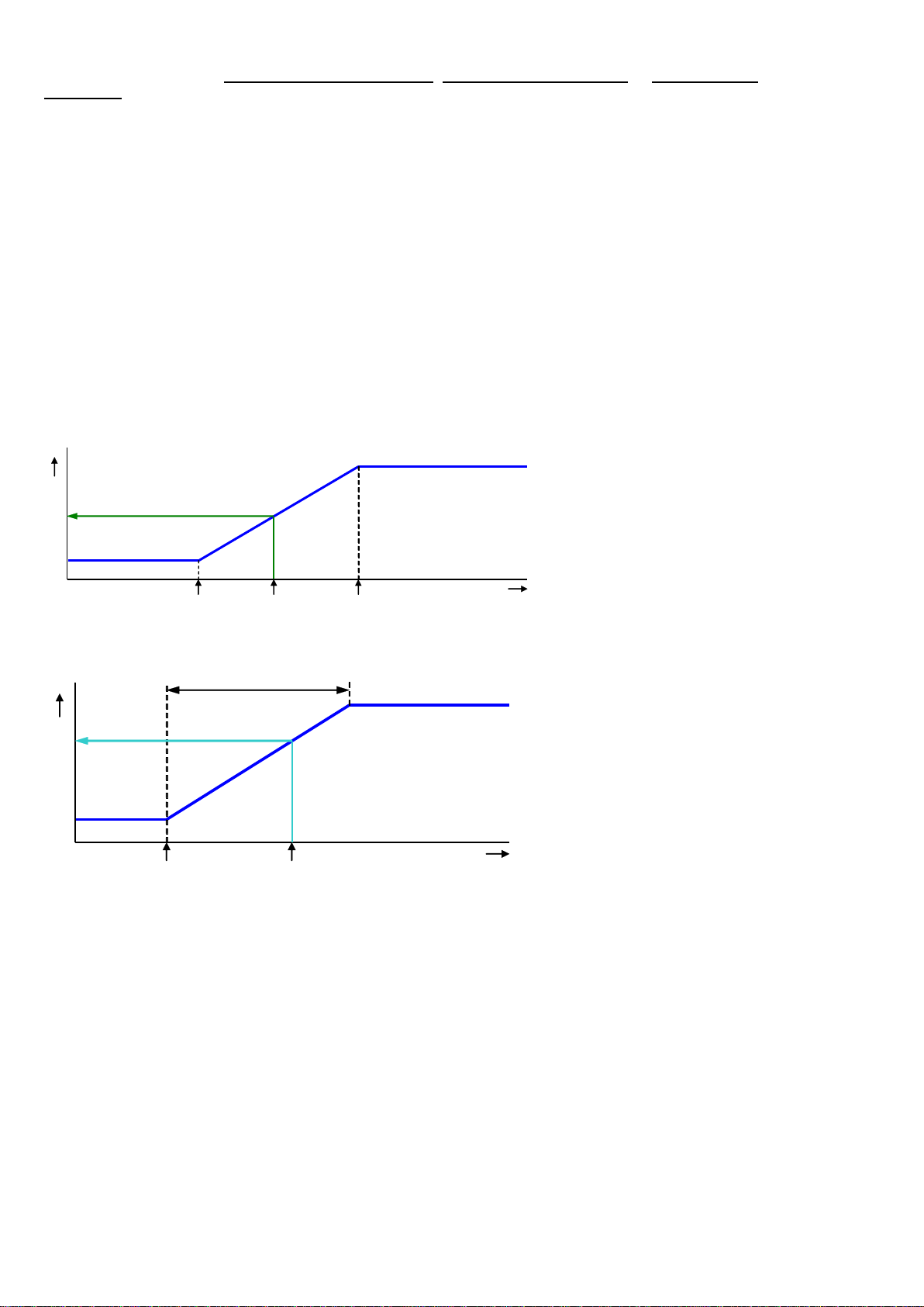
MAIN VENTILATION USING GROWTH CURVES
Climate settings, which are calculated in accordance with a curve, are
preceded by the text “Growth curve”.
The
behavior of the animals shows the quality of the climate. To avoid
having to continuously adjust the curve settings to the animal’s
behavior,
you can increase or decrease the calculated curve settings of the
first
column (+0.0°C/+0.0%).
Growth curve temperature:to increase or decrease the calculated house temperature.
Growth curve minimum:to increase or decrease the minimum ventilation.
Growth curve maximum:to increase or decrease the maximum ventilation.
Page 12 of 41
If the cursor is placed on Growth curve temperature, Growth curve minimum or Growth curve
maximum and you push the confirmation key the curve for the settings concerned will be displayed. You may
change the curve settings or switch off the curve. Press the cancel key to return to the previous window. If you
have switched off the curve, the text 'growth curve' will be replaced by the standard text and you can no longer
access the relevant curve settings from this window (the curve is off).
START FAN 2 / FAN 3
If the main ventilation consists of more ventilation controls, you have to set the percentage at which the 2nd /
3rd ventilation control have to be switched on (switch-on percentage relative to the total capacity of the
controlled ventilation group) behind “Start fan 2” and/or “Start fan 3”.
The entry behind ”Proportional” ”Step” shows the number of the ventilation control which is currently switched
on (1= 1st ventilation control, 2= 1st and 2nd ventilation control, 3= 1st, 2nd and 3rd ventilation control)
”Step”: step of the step control which is currently switched on.
If the capacity of the controlled ventilation group (compared to the total capacity) is less than the percentage
entered behind “Minimum ventilation”, the controlled group is always fully on.
AQC FLAP
Adjusting the control characteristic is only possible for an AQC flap without a measuring fan. If there is a
measuring fan in the controlled ventilation group, menu option “2 AQC flap” will not be displayed.
Minimum flap opening
Maximum flap opening = 100%
Flap opening [%]
Minimum
at ventilation
Main ventilation [%]
Current
ventilation
Current flap opening
Maximum
at ventilation
The AQC flap without a measuring
fan controls on the basis of the
calculated
main vent
ilation (main fan
output).
LEFT/RIGHT/FRONT/MIDDLE/REAR/RECIRCULATION/TOP AND BOTTOM
Bandwidth
Minimum
Maximum
VENTILATION [%]
Setting
Temperature [°C]
Current
Calculated
The ventilation groups
“Left/Right/Front/Middle/Rear/
Recirculation/Top and Bottom” are
identical as regards their settings and
they are all set in a similar manner. A
ventilation group can consist of a
maximum of 3 separate controls (flaps).
The temperature setting, bandwidth and
minimum and maximum ventilation then
apply to all three the controls (1, 2 and
3).
TEMPERATURE SETTING
The temperature on the basis of which the ventilation group controls; this setting is always relative to the house
temperature. The calculated temperature on the basis of which the ventilation group controls is shown behind
the temperature setting.
BANDWIDTH
The bandwidth determines the 'sensitivity' of the control. A short bandwidth will cause the control to react to a
rise in temperature very quickly. This is not good for the climate in the house, since it will result in too many
ventilation variations. That is why a bandwidth of 4 to 7°C, depending on the outside temperature, is to be
advised (also see 'Automatic bandwidth compensation' on page 18).
MINIMUM AND MAXIMUM VENTILATION
The minimum and maximum flap opening can be set here.
CURRENT TEMPERATURE
This line shows the current temperature on the basis of which the ventilation group is controlling.
Page 13 of 41
CALCULATED FLAP OPENING
●Control on the basis of temperature: The flap opening requirement is calculated on the basis of the
temperature measured, the bandwidth, the minimum and maximum flap opening.
●Control on the basis of ventilation: The flap opening requirement is calculated on the basis of the
current main ventilation, the minimum and maximum flap opening.
●Control on the basis of pressure difference: If the ventilation group controls on the basis of the preset
pressure difference and pressure control has been switched on (see page 16), the control will try to keep
the pressure difference in the house as constant as possible.
Characteristics:
The pressure setting is automatically adjusted to the outside temperature.
Any temperature differences in the house are considered when determining the flap positions.
The pressure control will be instantaneously switched-off if a ventilation alarm occurs at the main
ventilation control.
If a pressure alarm occurs the pressure control will be delayed switch-off (delay time = 5x pressure
integration time).
CURRENT FLAP OPENING
The current flap opening of the ventilation group is shown in this line.
FLAP CONTROL ON THE BASIS OF VENTILATION
Minimum flap
opening
The flap will never close further than the
"Minimum flap opening" percentage
setting.
Maximum
flap opening
The flap will never open further than the
"Maximum flap opening" percentage
setting.
Minimum at
ventilation
The flap will stay at the preset minimum if the main ventilation is less than this percentage. If
this percentage is exceeded, the flap will open further.
Maximum at
ventilation
The flap will be opened at its preset maximum if the main ventilation is more than this
percentage.
20
40
100
80
60
0
Maximum
Minimum
Minimum Maximum
Main ventilation [%]
Flap opening [%]

Page 14 of 41
HEATINGS
CONTROLLED HEATING
Heating
You can switch the heating on or off.
Temperature setting
The temperature on the basis of which the heating controls is relative to the house temperature, see page 10, if
a temperature of below 10.0°C is set. If a temperature equal to or higher than 10.0°C is set, this will be an
absolute setting.
Growth curve
If the cursor is on Growth curve temperature and you press the confirmation key the curve of the heating will
be displayed. You may change the curve settings or switch off the curve. Press the cancel key to return to the
previous screen. If you have switched off the curve, the text 'growth curve' will be replaced by the standard text
and you can no longer access the curve from this screen (the curve is off).
Bandwidth
The bandwidth determines the 'sensitivity' of the heating for temperature changes. The heating is controlled
from minimum to maximum within the bandwidth. If the bandwidth is too small, the heating very quickly reacts
to temperature changes. The switched heating has a fixed, installer-adjusted, switching hysteresis.
Minimum/maximum heating
Limiting the minimum/maximum force (heating capacity) of a controlled heating.
Current temperature
The current average temperature of the assigned sensors is displayed. Up to 4 temperature sensors can be
assigned to a heating control.
Current heating
Display of the current status of the heating and the calculated current flap position and/or heating capacity.
If -0% is calculated for the current heating (or the heating is switch off), the stop voltage will be sent out
instead of the minimum voltage setting (if house status = in use). If "Minimum heating" is activated, the
"minimum" voltage is applied to the output when the current temperature exceeds the temperature setting.
The current flap position or the current heating capacity is only displayed with controlled heating.
Minimum
Maximum heating
Heating [%]
Temperature
setting
House temperature [°C]
Current
temperature
Current heating
Bandwidth
House temperature
setting
Relative setting

Page 15 of 41
ON/OFF HEATING
If the heating consists of on/off
(non
-modulating) heating, you can
call up:
•
Today's operating hours.
•
Operating hours of the past 7
days.
•
The total number of operating
hours.
Erasing operating hours: Enter “yes”
behind “C
lear running hours”.
COOLING
ON/OFF COOLING
If the cooling consists of on/off (non-modulating) cooling, you can call up the operating hours.
SOAKING
REDUCTION
RUNNING HOURS
Soaking
If the house is not in use, you can use the “Soaking” function (this option is only available on cooling 1). As
soon as the house status changes, “Soaking” will be switched “off” to prevent the soaking starting immediately
after you switch the house to “not in use”.
Reduction
Limiting the current cooling and to prevent that too much cold air being drawn into the house when the outside
tem1perature is low and the current house temperature is higher than the house temperature setting:
•You can set a temperature range within which the reduction is to be active by setting a temperate difference
(relative to the “Temperature setting” cooling) at “Start reduction” and at “Reduce until”.
•The current outside temperature is shown.
•Setting the maximum (relative) reduction at “Reduction max.”
Running hours
If the cooling consists of on/off (non-modulating) cooling, you can call up:
•Today's operating hours.
•Operating hours of the past 7 days.
•The total number of operating hours.
Erasing operating hours: Enter “yes” behind “Clear running hours”.

Page 16 of 41
MISCELLANEOUS CONTROLS
PRESSURE CONTROL
Controlling the flaps on the basis of a preset under pressure guarantees an
optimum flow pattern for the incoming air.
The pressure setting and the current pressure measured are used to
determine the “Calc. ventilation press.”.
The
pressure controlled flaps are readjusted every 2 minutes (gradual
control). At large deviations between setting and current pressure it can
take some time before the flaps have reached the calculated position. By
changing the "calculated ventilation pressu
re" value you can speed up the
settling time for the flaps.
External input
Items such as the status of the hatches that provide access to an open-air run can be connected to the external
input. The openings of these hatches enable a lot of cold air to enter the house which causes a significant drop
in the house temperature, specifically at the bottom of the house. If the pressure control was not switched off,
the air speed and the temperature difference in the house would increase enormously. As this may easily cause
a draught which would affect the animals the pressure control is switched off as soon as the hatches are open.
The inlet flaps, which were being controlled on the basis of pressure, are now temperature-controlled.
HUMIDIFICATION
If “Cooling 1” and “Humidification”
are connected to the same
(controlled) output, the output will
be energized based on the highest
calculated value of both controls.
On/off Humidification control
Modulating humidification control
This window enables you to switch the humidification control on or off and to set the relative humidity
percentage. Below this percentage the humidification control is active.
TEMPERATURE CONTROLS
The temperature control can be
adjusted as a “heating” or as a
“cooling” control. This can be a
controlled or a switched control,
depending on the type of output.

Page 17 of 41
TEMPERATURE CONTROL AS HEATING
If temperature control has been set as heating, the temperature control is set identically to a heating, see page
14, with the exception of the minimum heating. The minimum heating can be set separately.
TEMPERATURE CONTROL AS COOLING
If temperature control has been set as cooling, the temperature control is set identically to the cooling on
page 15.
Temperature setting: see page 10, Relative or absolute temperature setting.
TEMPERATURE MONITORING
The temperature monitoring function is activated by your installer (max.
8 sensors). The current measurement of each sensor is compared with
the measurement of one minute ago. If the measurement is within the
limits, the previous measurement is made equal to the current
measurement and a new measurement is s
tarted.
An alarm is given if:
•
The temperature increase in that minute greater or equal than the
relative limits.
•
Increases the temperature of the sensor above the absolute limit,
then there is also alarm.
The temperature monitor alarm occurs only when a
positive difference is
detected (not when the temperature drops down).
COMPENSATIONS CLIMATE CONTROL
Compensations ensure that the setting is increased and/or decreased
depending on:
●
with or without night settings;
●
the current outside temperature;
●
the current RH;
●
The current CO2level.
●
Wind speed and wind direction.
For RH and CO
2
correction, the largest value of both corrections is decisive
for the eventual adjustment of the ventilation/flap position.
NIGHT SETTING
Creating natural temperature behaviour between day and night by reducing the temperature setting by a couple
of degrees during the night.
•Setting the active period for the night settings.
•Setting the number of degrees by which the house temperature has to be increased/decreased during this
period.
•Setting the percentage by which the minimum ventilation is to be increased/decreased during the night.
Note! The compensation of the minimum ventilation is a percentage of the minimum ventilation.
Night setting house temperature:
2
1,0°C -1,0 = 20,0°C
Night setting minimum ventilation:
-
10% of 10.7% = -1.1% =>
10
.7%-1.1% = 9,6%
1 min.
Current measurement
Measurement of 1
minute ago
Temp. difference

Page 18 of 41
TEMPERATURE
Activate the temperature compensation to prevent rapid temperature drops in the house (which usually occur in
the spring and autumn).
“Reduce temp. compensation”:
Determines the speed at which the corrected house temperature is
controlled down to the preset house temperature in the event of a
drop in temperature.
Switch off temperature compensation:
Set a maximum temperature compensation of 0.0°C.
Example:
Temperature exceeded
=
Current house temperature - (House temperature setting + bandwidth)
=
28.1 °C - (20 °C + 4.0 °C) = 4.1 °C
However, the temperature correction can never be more than the
maximum temperature compensation. This means that in the above
example it can never be more than 3.0°C (maximum setting)
instead of 4.1 °C (calculated excess value). The corrected
temperature setting becomes equal to: house temperature setting +
temperature correction = 20.0 °C + 3.0 °C = 23.0 °C.
In this example, the time in which the house temperature is
controlled back to the temperature setting is:
(House temperature correction / max. temperature compensation) x
1 hour => (3.0°C / 0.2 °C) x 1 hour = 15 hours.
VENTILATION
Control of optimal ventilation based on the fill ratio. The fill ratio is calculated on the basis of the maximum
number of animals in the house and the current number of animals in the house (animal group 1 + animal
group 2).
BANDWIDTH COMPENSATION
If the outside temperature is part of the installation, the bandwidth of the main ventilation and/or air inlet flaps
can automatically be adjusted to changes in outside temperature.
Setting bandwidth compensation to obtain:
•A larger bandwidth at low outside temperature.
•A smaller bandwidth at high outside temperature
Current temperature outside = 10°C
Current temperature outside = 30°C
This setting is used to adjust the bandwidth to the current outside temperature.
House temperature setting
20.0
°C
Maximum temperature compensation
3.0
°C
Reduce temperature compensation 0.2
°C
/h
Bandwidth 4.0
°C
Current house temperature
28.1
°C
Corrected setting house temperature
23.0
°C
Max.
Min.
Ventilation [%]
House temperature[°C]
Reduction per hour
20
25
30
23
3°C
0°C 30°C 40°C
3°C
0°C
6°C
1°C
2°C
4°C
5°C
7°C
8°C
20°C
10°C
Corrected bandwidth [%]
Outside temperature [°C]
Bandwidth diminished
from 4.0°C to 3.0°C
0°C 30°C 40°C
3°C
0°C
6°C
1°C
2°C
4°C
5°C
7°C
8°C
20°C10°C
Outside temperature [°C]
Corrected bandwidth [%]
Bandwidth increased
from 4.0°C to 5.0°C

Page 19 of 41
Example bandwidth compensation:
Bandwidth
Bandwidth compensation
Bandwidth compensation starts at outside temperature:
4.0
-2.5
20
°C
%/°C
°C
At an outside temperature of 20°C the bandwidth is 4.0°C. If the outside temperature drops to 10.0°C the
bandwidth is increased by 1.0°C.
ΔT = Current outside temperature-bandwidth compensation starts at outside temp. = 10.0°C-20.0°C= -10.0°C
Correction bandwidth = ((ΔT * Bandwidth compensation) * Bandwidth) / 100%
Correction bandwidth = (-10.0°C * -2.5%/°C) * (4.0°C / 100%) = 1.0°C
The corrected bandwidth is: 4.0°C + 1.0°C = 5.0°C
But if the outside temperature increase to 30.0°C the bandwidth will be diminished with 1.0°C to 3.0°C (4.0°C
- 1.0°C = 3.0°C).
The bandwidth is limited: the upper limit is 20.0°C; the lower limit is 1.0°C.
COMPENSATION MINIMUM VENTILATION
Automatically adjusted the minimum ventilation to the actual outside temperature.
“Start outside temperature”:
The outside temperature at which the calculated minimum ventilation should
be equal to the set minimum.
“Compens. minimum ventilation”:
The percentage at which the minimum ventilation should be corrected per
°C of change in outside temperature.
Example:
Minimum ventilation
20.0
%
Compensation minimum ventilation
1,0
%/°C
Start outside temperature
15.0
°C
till
-10.0
°C
Current outside temperature
5.0
°C
(5,0°C-15,0°C)*1,0%/°C*20,0%/100%=-2%
Calculated minimum ventilation (20,0-2,0)
18
%
Current outside temperature
30.0
°C
(30,0°C-15,0°C)*1,0%/°C*20,0%/100%=+3%
Calculated minimum ventilation (20,0+3,0)
23,0
%
The calculated compensation of the minimum ventilation will be valid for all ventilation groups.
COMPENSATION REDUCTION
If a heat exchanger is used, the reduction percentage can be adjusted (compensated) automatically to the
current outside temperature. The smaller the difference between the outside temperature and the preset house
temperature, the greater the reduction compensation.
Example
Main ventilation:
Temperature setting
20.0
°C
Bandwidth
4.0
°C
Current house temperature
21.6
°C
Outside temperature:
Current temperature outside
18.3
°C
Heat exchanger:
Compensation reduction
-10.0
%/°C
ΔT (fix value)
-5.0
°C
Start reduction
75.0
%
Correction “reduction”
= (start reduction x ((current temperature outside - (temperature setting + ΔT)) x
compensation reduction)
Corrected “Start reduction”
= Start reduction + correction reduction
Start
= (Bandwidth * corrected “Start reduction”)/100%
Example
Correction “reduction”
(75% x ((18.3°C – (20.0°C-5.0°C)) x -10%/°C) / 100%= -24.75%
Corrected “Start reduction”
75% + (-24.75)% = 50.25%
50.3%
Start
(4.0°C * 50.25%)/100% = 2.01°C
2.0°C
Minimum ventilation [%]
Outside temperature[°C]
5.0
30.0
15.0
15
20
10
25
30

Page 20 of 41
PRESSURE CONTROL
The under pressure can
automatically be adjusted to the
current outside temperature:
•Outside temperature is low
=> higher under pressure.
•Outside temperature is high
=> lower under pressure (cold
air is heavier than warm air)
Start outside temperature Absolute
Start outside temperature Relative
Absolute
The setting from where the pressure is compensated is a fixed temperature setting.
Relative
The setting from which pressure is compensated increases/decreases “run along” with the house temperature.
“From outside temperature” = temperature difference relative to the house temperature.
Under pressure [Pa]
Outside temperature [°C]
15
30
25
10
20
Max.
30
Min.
5
20
Fixed setting (absolute)
Under pressure [Pa]
Outside temperature [°C]
15
30
25
10
20
Max.
30
Min.
5
20
House temperature (25,0°C)
ΔT
-5.0°C
Setting follows the house temperature
(relative)
The compensated pressure is limited by the set minimum and maximum pressure.
RH
The ventilation / flap position and set house temperature can be controlled based on relative humidity.
Absolute RH = the water vapour content per cubic metre.
Cold air can contain less water vapour than hot air. If the air temperature is 10°C, the air can hold approx. 9.8g
of water vapour per m³ and at a temperature of 20°C this can be approx. 18.6g/m³.
Example
If the relative humidity is 70%
Air of a temperature of 10 °C can contain approx. 6.9 g/m³ (0.7*9.8)
Air of a temperature of 20 °C can contain approx. 13.0 g/m³ (0.7*18.6).
RH compensation without RH outside air
RH compensation only influences ventilation. This means that the ventilation effort will be greater if the value
measured is higher than the value set for “RH compensation”.
The corrected ventilation is limited
by the pre-set maximum (Max.).
Compensation = ((current RH – RH
compensation) * factor.
Compensation ventilation
Factor 0.0 = RH compensation does not affect the ventilation.
Factor 9.9 = RH compensation has a maximum effect on the ventilation.
This manual suits for next models
1
Table of contents
Other STIENEN Desktop manuals

Popular Desktop manuals by other brands


Crestron
Crestron EDU-500 quick start

Acer
Acer Veriton 9100 user guide

HP
HP Desktop PC 390 Disassembly instructions

Sony
Sony PCV-W20 - VAIO - 512 MB RAM Online help

HP
HP 290 G1 PCI Microtower Business Product End-of-Life Disassembly Instructions

HP
HP 8100 - Elite Convertible Minitower PC Hardware reference guide