Stilcondal EOS Veranda on Ceiling User manual

Manual Instalación
Veranda EOS Sobre Techo
Assembly Instructions for EOS Veranda on Ceiling
Manuel Installation Veranda EOS Sur Toit
Manuale di Installazione Veranda EOS a Tetto
Veranda EOS Sobre-Techo CERRADO
CLOSED EOS Veranda on Ceiling
Veranda EOS Sur-Toit FERMÉ
Veranda EOS su Tetto CHIUSO
Veranda EOS Sobre-Techo ABIERTO
OPENED EOS Veranda on Ceiling
Veranda EOS Sur-Toit OUVERT
Veranda EOS su Tetto APERTO
PROTECCIÓN SOLAR
stilcondal

CÓDIGO / CODE / CODICE
DESCRIPCIÓN DEL ARTÍCULO / ARTICLE DESCRIPTION / DESCRIPTION ARTICLE / DESCRIZIONE
80110065
J. PERFILES COFRE EOS BLANCO 4M / SET OF PROFILES FOR EOS BOX, WHITE 4M
J. PROFILS COFFRE EOS BLANC 4M / SET PROFILI CASSONETTO EOS L=4M BIANCO
80110066
J. PERFILES COFRE EOS RAL ESP. 4M / SET OF PROFILES FOR EOS BOX, SPECIAL RAL 4M
J. PROFILS COFFRE EOS RAL SPÉCIAL 4M / SET PROFILI CASSONETTO EOS L=4M RAL SPECIALE
80110002
J. PERFILES COFRE EOS BLANCO 5M / SET OF PROFILES FOR EOS BOX, WHITE 5M
J. PROFILS COFFRE EOS BLANC 5M / SET PROFILI CASSONETTO EOS L=5M BIANCO
80110007
J. PERFILES COFRE EOS RAL ESP. 5M / SET OF PROFILES FOR EOS BOX, SPECIAL RAL 5M
J. PROFILS COFFRE EOS RAL SPÉCIAL 5M/ SET PROFILI CASSONETTO EOS L=5M RAL SPECIALE
80110051
J. PERFILES COFRE EOS BLANCO 6M / SET OF PROFILES FOR EOS BOX, WHITE 6M
J. PROFILS COFFRE EOS BLANC 6M / SET PROFILI CASSONETTO EOS L=6M BIANCO
80110056
J. PERFILES COFRE EOS RAL ESP. 6M / SET OF PROFILES FOR EOS BOX, SPECIAL RAL 6M
J. PROFILS COFFRE EOS RAL SPÉCIAL 6M / SET PROFILI CASSONETTO EOS L=6M RAL SPECIALE
80110068
J. PERFILES COFRE EOS BLANCO 7M / SET OF PROFILES FOR EOS BOX, WHITE 7M
J. PROFILS COFFRE EOS BLANC 7M / SET PROFILI CASSONETTO EOS L=7M BIANCO
80110069
J. PERFILES COFRE EOS RAL ESP. 7M / SET OF PROFILES FOR EOS BOX, SPECIAL RAL 7M
J. PROFILS COFFRE EOS RAL SPÉCIAL 7M / SET PROFILI CASSONETTO EOS L=7M RAL SPECIALE
80110099
PERFIL BARRA CARGA EOS BLANCO 4M / EOS CHARGE PROFILE, WHITE 4M
PROFIL BARRE DE CHARGE EOS BLANC 4 M / PROFILO TERMINALE EOS L=4M BIANCO
80110100
PERFIL BARRA CARGA EOS RAL ESP. 4M / EOS CHARGE PROFILE, SPECIAL RAL 4M
PROFIL BARRE DE CHARGE EOS 4M RAL SPÉCIAL / PROFILO TERMINALE EOS L=4M RAL SPECIALE
80110085
PERFIL BARRA CARGA EOS BLANCO 5M / EOS CHARGE PROFILE, WHITE 5M
PROFIL BARRE DE CHARGE EOS BLANC 5 M / PROFILO TERMINALE EOS L=5M BIANCO
80110090
PERFIL BARRA CARGA EOS RAL ESP. 5M / EOS CHARGE PROFILE, SPECIAL RAL 5M
PROFIL BARRE DE CHARGE EOS 5 M RAL SPÉCIAL / PROFILO TERMINALE EOS L=5M RAL SPECIALE
80110092
PERFIL BARRA CARGA EOS BLANCO 6M / EOS CHARGE PROFILE, WHITE 6M
PROFIL BARRE DE CHARGE EOS BLANC 6M / PROFILO TERMINALE EOS L=6M BIANCO
80110097
PERFIL BARRA CARGA EOS RAL ESP. 6M / EOS CHARGE PROFILE, SPECIAL RAL 6M
PROFIL BARRE DE CHARGE EOS 6M RAL SPÉCIAL / PROFILO TERMINALE EOS L=6M RAL SPECIALE
80110102
PERFIL BARRA CARGA EOS BLANCO 7M / EOS CHARGE PROFILE, WHITE 7M
PROFIL BARRE DE CHARGE EOS BLANC 7M / PROFILO TERMINALE EOS L=7M BIANCO
80110103
PERFIL BARRA CARGA EOS RAL ESP. 7M / EOS CHARGE PROFILE, SPECIAL RAL 7M
PROFIL BARRE DE CHARGE EOS 7M RAL SPÉCIAL / PROFILO TERMINALE EOS L=7M RAL SPECIALE
80110009
KIT ANCLAJE EOS S/TECHO BLANCO / SET OF FIXING SUPPORTS FOR EOS, WHITE
KIT FIXATION S/TOIT BLANC / KIT SUPPORTO VERANDA EOS SU TETTO BIANCO
80110014
KIT ANCLAJE EOS S/TECHORALESP. / SET OF FIXING SUPPORTS FOR EOS, SPECIAL RAL
KIT FIXATION S/TOIT RAL SPÉCIAL / KIT SUPPORTO VERANDA EOS SU TETTO RAL SPECIALE
80110044
KIT TAPAS COFRE EOS BLANCO / SET OF CAPS FOR EOS BOX, WHITE
KIT EMBOUTS COFFRE EOS BLANC / KIT TAPPI CASSONETTO EOS BIANCO
80110049
KIT TAPAS COFRE EOS RAL ESP. / SET OF CAPS FOR EOS BOX, SPECIAL RAL
KIT EMBOUTS COFFRE EOS RAL SPÉCIAL / KIT TAPPI CASSONETTO EOS RAL SPECIALE
80110128
J. TAPAS EMPALME CAJÓN EOS BLANCO / SET OF JOINT CAPS FOR EOS BOX, WHITE
J. EMBOUTS D’ABOUTAGE CAISSON EOS BLANC / SET TAPPI GIUNZIONE CASSONETTO EOS BIANCO
80110129
J. TAPAS EMPALME CAJÓN EOS RAL ESP. / SET OF JOINT CAPS FOR EOS BOX, SPECIAL RAL
J. EMBOUTS D’ABOUTAGE CAISSON EOS RAL SPÉCIAL / SET TAPPI GIUNZIONE CASSONETTO EOS RAL SPECIALE
80110120
J. GUÍAS EOS BLANCO 2.5M / SET OF GUIDES FOR EOS, WHITE 2,5M
J. PROFILS DE GUIDAJE BLANC 2.5M / COPPIE GUIDE EOS BIANCO L= 2,5M
80110125
J. GUÍAS EOS RAL ESP. 2.5M / SET OF GUIDES FOR EOS, SPECIAL RAL 2,5M
J. PROFILS DE GUIDAJE RAL SPÉCIAL 2.5M / COPPIE GUIDE EOS RAL SPECIALE L=2,5M
80110016
J. GUÍAS EOS BLANCO 3M / SET OF GUIDES FOR EOS, WHITE 3M
J. PROFILS DE GUIDAJE BLANC 3M / COPPIE GUIDE EOS BIANCO L=3M
80110021
J. GUÍAS EOS RAL ESP. 3M / SET OF GUIDES FOR EOS, SPECIAL RAL 3M
J. PROFILS DE GUIDAJE RAL SPÉCIAL 3M / COPPIE GUIDE EOS RAL SPECIALE L=3M
80110023
J. GUÍAS EOS BLANCO 4M / SET OF GUIDES FOR EOS, WHITE 4M
J. PROFILS DE GUIDAJE BLANC 4M / COPPIE GUIDE EOS BIANCO L=4M
80110028
J. GUÍAS EOS RAL ESP. 4M / SET OF GUIDES FOR EOS, SPECIAL RAL 4M
J. PROFILS DE GUIDAJE RAL SPÉCIAL 4M / COPPIE GUIDE EOS RAL SPECIALE L=4M
80110030
J. GUÍAS EOS BLANCO 5M / SET OF GUIDES FOR EOS, WHITE 5M
J. PROFILS DE GUIDAJE BLANC 5M / COPPIE GUIDE EOS BIANCO L=5 M
80110035
J. GUÍAS EOS RAL ESP. 5M / SET OF GUIDES FOR EOS, SPECIAL RAL 5M
J. PROFILS DE GUIDAJE RAL SPÉCIAL 5M / COPPIE GUIDE EOS RAL SPECIALE L=5M
80110037
J. GUÍAS EOS BLANCO 6M / SET OF GUIDES FOR EOS, WHITE 6M
J. PROFILS DE GUIDAJE BLANC 6M / COPPIE GUIDE EOS BIANCO L=6M
80110042
J. GUÍAS EOS RAL ESP. 6M / SET OF GUIDES FOR EOS, SPECIAL RAL 6M
J. PROFILS DE GUIDAJE RAL SPÉCIAL 6M/ COPPIE GUIDE EOS RAL SPECIALE L=6M
RECOMENDACIONES DE USO:
RECOMMANDATIONS D’UTILISATION:
USE RECOMMENDATIONS:
RACCOMANDAZIONI D’USO:
Guías: 2,5 m / Guides: 2,5 m
Profil 2,5 m / Guide: 2,5 m
Guías: 3 m, 4 m / Guides: 3 m, 4m
Profil 3 m, 4 m / Guide: 3 m, 4 m
Guías: 5 m, 6 m / Guides: 5 m, 6m
Profil 5 m, 6 m / Guide: 5 m, 6 m
Longitud de corte de guía S /Cutting adjustments for theS guide
Longueur coupe profil de guidage S /Lunghezza di taglioguida S
Mínimo 1,6 m / 1,6 m minimum
Minimum 1,6 m / Minimo 1,6 m
Mínimo 2,5 m / 2,5 m minimum
Minimum 2,5 m / Minimo 2,5 m
Mínimo 4 m / 4 m minimum
Minimum 4 m / Minimo 4 m
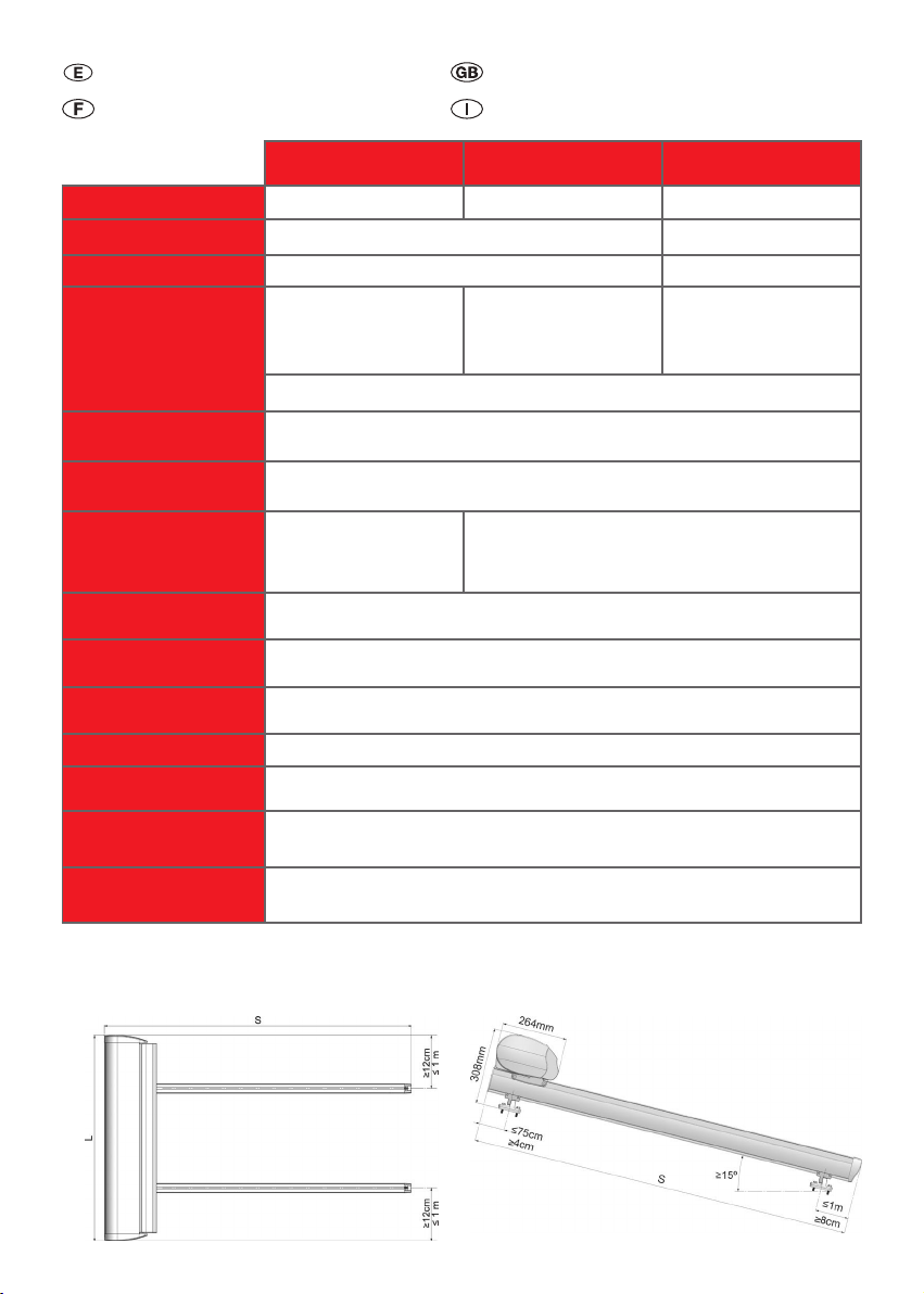
Longitud cofre L /L box length
Longueur coffre L /Lunghezza cassonetto L
Máximo 6 m / 6 m maximum
Maximum 6 m / Massimo 6 m
Máximo 5 m / 5 m maximum
Maximum 5 m / Massimo 5 m
Pies / Supports / Pieds / Supporti inferiori
Mínimo 2 por guía / Minimum 2 per guide
Minimum 2 par profil de guidage / Minimo 2 per guida
Mínimo 3 por guía / Minimum 3 per guide
Minimum 3 par profil de guidage/Minimo 3 per guida
Motor* / Motor* / Moteur* / Motore*
Mínimo 50 N*m/ 50 N*m Minimum
Minimum 50 N*m/ Minimo 50 N*m
(1)
(GM-50 Cod: 60050006) (ARGOS 50 Cod: 60050105)
(1)
Si raccomanda minimo 80 N*m per l’Italia
(DAYTONA 80 Cod: 6C2.61250)
Mínimo 80 N*m/ 80 N*m Minimum
Minimum 80 N*m/ Minimo 80 N*m
(2)
(GM-80 Cod: 60050009)
(2)
Si raccomanda minimo 100 N*m per l’Italia
(DAYTONA 100 Cod: 6C2.61290)
Mínimo 120 N*m/ 120 N*m Minimum
Minimum 120 N*m/ Minimo 120 N*m (3)
(GM-120 Cod: 60050011)
(3)
Italia: (DAYTONA 120Nm
Cod: 6C2.61350)
Nota: se recomienda la utilización del motor tipo cofre como Somfy o similares / Note: it is recommended to use a motor for box like Somfy or similar
Note:onrecommande l´utilisation d´un moteur type coffre comme Somfy ou similaire/ Per motorielettronici si consiglia l’uso di motoriSomfy o similari
Eje / Tube / Axe / Rullo
Eje Ø 85x1.2 mm ojiva, rizado, longitudes 4 m, 5 m, 6 m, 7 m / Ø 85x1,2 mm tube with ogive, crinkle, 4 m, 5 m, 6 m, 7 m length
Axe Ø 85 x 1,2 mm à gorge, ondulé 4 m, 5 m, 6 m, 7 m / Rullo Ø 85x1.2 mm ogiva, con nervature, lunghezza 4 m, 5 m, 6 m, 7 m
(Cods: 80030052, 80030050, 80030051, 80030053-6B4.3585/L)
Casquillo / Round cap / Embout / Calotte
Casquillo Ø 85-ojiva, agujero Ø 14 mm / Round cap of Ø 85 ogive, with round hole Ø 14 mm
Embout Ø 85 à gorge, trou Ø 14 mm / Calotte Ø 85 ogiva, foro Ø 14 mm
(Cod: 80020086)
Adaptador Motor-Eje / Motor-Tube Adapter
Adapteur Moteur-Axe / Adattatore Motore - Rullo
Adaptador para eje ojiva Ø85 y motor serie 50
Adapter for Ø 85 ogive tube and 50 Series motors
Adapteur pour axe Ø85 à gorge et moteur sèrie 50
Adattatore per rullo ogiva Ø85 serie-50(4)
(Cods: 60070054, 6C4.6047/T)
(4)
Italia: Serie 60 (Cod: 6C4.60470)
Adaptador para eje Ø85-ojiva y motor serie 60
Adapter for Ø 85 ogive tube and 60 Series motors
Adapteur pour axe Ø85 à gorge et moteur serie 60
Adattatore per rullo ogiva Ø85 e motore serie 60
(Cods: 60070050, 6C4.60470)
Voladizo lateral / Lateral cantilever
Saillie latérale / Sporgenza laterale
Máximo 1 m - Mínimo 12 cm / 1 m maximum - 12 cm minimum / Maximum 1 m - Minimum 12 cm / Massimo 1 m – Minimo 12 cm
Se recomienda que sea el menor posible / It is recommended to use as small as possible
On recommande la moindre posible / Si raccomanda che sia il più piccolo possibile
Voladizo trasero / Rear cantilever
Saillie arrière / Sporgenza posteriore
Máximo 75 cm / 75 cm maximum / Maximum 75 cm / Massimo 75 cm
Se recomienda que sea el menor posible / It is recommended to use as small as possible
On recommande la moindre posible / Si raccomanda che sia il più piccolo possibile
Voladizo delantero / Frontal cantilever
Saillie avant / Sporgenza anteriore
Máximo 1 m / 1 m maximum / Maximum 1 m / Massimo 1 m
Se recomienda que sea el menor posible / It is recommended to use as small as possible
On recommande la moindre posible / Si raccomanda che sia il più piccolo possibile
Inclinación / Slope / Inclinaison / Inclinazione
Mínimo 15º / 15º minimum / Minimum 15º / Minimo 15º
Cosido de lona / Fabric sewing
Toile cousue / Tessuto cucito
Realizar refuerzos a la lona de 10 cm de ancho a 10 cm de los bordes / Make a 10 cm width reinforcement around 10 cm from the fabric b orders
Réaliser des renforts sur la toile de 10 cm de large à 10 cm des bords / Eseguire dei rinforzi sul tessuto di 10 cm di larghezza a 10 cm dai b ordi
Lona recomendada / Recommended fabric
Toile recommandée / Tessuto consigliato
Lona poliéster, resinada a una cara, peso máximo 400 gr/m², resistencia a la rotura mínima de 200 daN según ISO-13934-1 / Polyester fabric, with
resin on one side, 400 gr/m² maximum weight, minimum rupture strength of 200 daN according to ISO-13934-1 / Toile polyester, résinée sur une
face, poids maximum 400 gr/m² résistance á la déchirure mínimum de 200 daN selon norme ISO-13934-1 / Tessuto in poliestere, resinato da una
parte, peso massimo 400 gr/m², resistenza alla rotura minima di 200 daN secondo ISO-13934-1
Punto Rodamiento / Ball bearing round pivot
Point roulement à billes
Supporto foro tondo con cuscinetto
Se recomienda incluir el punto con rodamiento H=20 mm, para lo cual se utilizará el casquillo Ø85 espiga Ø12 mm
It is recommended to use the round pivot with H=20 mm ball bearing, thus, the Ø85 round cap with Ø12 mm pivot should be used
Point roulement à billes recommandé H=20 mm, avec embout mâle Ø85, sortie ronde Ø12mm
Supporto foro tondo con cuscinetto H=20 mm, per il quale si userà calotta Ø85 perno Ø12 mm
* El par mínimo es para instalaciones con 2 guías. Para instalaciones con 3 o más guías, aumentar proporcionalmente el par motor.
* The minimum torque is for installations with 2 guides. For installations with 3 or more guides, progressively increase the motor torque.
* Le couple moteur minimum indiqué pour installations avec 2 profiles de guidage. Pour installations avec 3 de profils de guidage ou plus, augmenter proportionellement le couple moteur.
* La coppia minima è per l’installazione con 2 guide. Per installazione con 3 o piu’ guide aumentare progressivamente la coppia minima (5)
.
(5)
Italia: Attenzione: non e’ possibile installare con 3 o piu’ guide.

MONTAJE EN FÁBRICA:
ASSEMBLAGE A L’USINE:
Paso 1: Ajustar la longitud de las guías:
• Desmontar la tapa trasera y las garras.
• Cortar la parte sobrante de la guía. Ver longitudes mínimas de
corte en la tabla de “Recomendaciones de Uso” al principio
del manual. Muy importante: las dos guías han de cortarse a
la misma longitud ±1mm.
• Retirar la viruta del interior del perl, volcándolo hacia abajo
y/o con un pincel; jamás con pistola de aire.
• Volver a meter las garras en la guía; atornillar la tapa trasera;
poner la garra trasera atrás a tope y apretarla a fondo.
Step 1: Adjust the guides length:
• Take apart the rear cap and the claws.
• Cut the spare part of the guide. Check minimum lengths for
cutting adjustments at the “Use Recommendations” table at the
beginning of this manual. Very important: the two guides must
be cut to the same distance
±
1mm.
• Take out the shaving from inside the prole with the aid of a
brush by turning downwards (never use an air gun).
• Put again the claws in the guide; screw down the rear cap;
place the rear claw at the back and tighten thoroughly.
1: Ajuster la longueur des prols de guidage:
• Enlever le couvercle arrière et les xations.
• Couper la partie saillante du prol de guidage. Voir
les longueurs minimales de coupe sur le tableau
“Recommandations d’Utilisation” au commencement du
manuel. Très important: les deux prols de guidage doivent
être coupés à la même mesure ±1mm.
• Enlever les copeaux de l’intérieur du prol à l’aide d’un
pinceau mais jamais au pistolet à air.
• Remettre les xations sur le prol de guidage; visser le
couvercle arrière, placer la xation à l’extrémité arrierè et
serrer à fond.
Fase 1: Regolare la lunghezza delle guide:
• Rimuovere il tappo sul lato opposto al carrello di traino.
• Tagliare la parte in eccesso della guida. Controllare la lunghezza
minima del taglio sulla tabella “Raccomandazione d’uso”
all’inizio del manuale. Molto importante: le due guide devono
essere tagliate nella stessa lunghezza ±1mm.
• Rimuovere le bave dall’interno del prolo, abbassandolo con
una spazzola, mai con una pistola d’aria.
• Rimettere il tappo sulla guida, avvitare le viti di ssaggio
posteriori al tappo (stringere a fondo).
ASSEMBLY AT THE FACTORY:
MONTAGGIO IN FABBRICA
Llave 13 / 13 tool
Clé 13 / Chiave 13
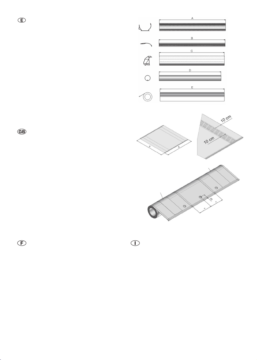
Paso 2: Cortar los perles, eje y lona a medida:
• Perl inferior y perl superior: A=B=L-67mm.
Muy importante: A=B±0.5 mm.
• Perl barra de carga: C=L-85 mm.
• Eje: D=L-87 mm.
• Lona: E=(L-100 mm) x (S).
Las medidas D y E son las aplicables cuando se
usan motor, eje, adaptador y cápsula de Gaviota
Simbac (ver tabla “Recomendaciones de Uso” al
principio del manual).
Se recomienda el usodelona con costuras reforzadas.
Poner agujeros dedrenaje en lalona (ollaos),
centrados entre las costuras, uno por paño y a 50mm
del borde frontal (ver gura).
En el caso de usar punto con rodamiento,
ver longitud de corte del eje en su manual de
instrucciones especíco.
Step 2: Cut made to measure the proles, tube and fabric:
• Lower and upper prole : A=B=L-67mm.
Very important : A=B±0.5 mm.
• Charge prole : C=L-85 mm.
• Tube : D=L-87 mm.
• Fabric : E=(L-100 mm) x (S).
D and E measurements are applicable whenever a Gaviota
Simbac’s motor, tube, adaptor and cap are used (check
“Use Recommendations” table at the beginning of this
manual).
It is recommended the use of fabric with reinforced
sewing.
Use drainage holes, centred between the sewing, one per
piece, at least 50 mm distance from the frontal border
(see the drawing).
Whenever using ball bearing round pivot, check the tube
cutting adjustment in its specic assembly instructions.
2: Couper les prols, axe et toile sur mesure:
• Prol inférieur et prol supérieur:A=B=L-67mm.
Très important : A=B±0.5 mm.
• Prol barre de charge : C=L-85 mm.
• Axe : D=L-87 mm.
• Toile : E=(L-100 mm) x (S).
Les mesures D et E s’appliquent quand on
utilise un moteur, axe, adapteur et embout de
Gaviota Simbac (ver tableau « Recommandations
d’Utilisation » au commencement du manuel).
On recommandel’utilisation de toile à coutures
renforcées.
Percer des trous dedrainage sur la toile, centrés entre
les coutures,un par section, et à 50 mm du bord
frontal (voir dessin).
En cas d’utiliser un pointderoulement à billes, vérier
la longueur decoupedel’axe dans son manuel
d’utilisation spécique.
Fase 2: Tagliare i proli, rullo e tessuto a misura:
• Prolo inferiore eprolo superiore: A=B= L - 67mm.
Molto importante: A=B ±0.5mm.
• Prolo terminale: C=L -85 mm.
• Rullo D=L -87 mm.
• Tessuto : E= (L-100 mm) x (S).
Le misureD eE sono applicabili quando si usail motore,
il rullo,l’ adattatore ela calotta di Gaviota Simbac (Vedi
tabella “Raccomandazioni d’uso” all’iniziodel manuale).
Si raccomanda l’utilizzo di tessuto con cuciture
rinforzate.
Fare dei buchi di drenaggio nel tessuto, centrati
tra le cuciture, rinforzate, ed a 50 mm dal bordo
anteriore (vedi gura).
Nel caso di utilizzo supporto foro tondo con
cuscinetto H=20 mm vedere il taglio lunghezza del
rullo sul manuale di istruzioni.
REFUERZO
REINFORCEMENT
RENFORCE
RINFORZO
REFUERZO
REINFORCEMENT
RENFORCE
RINFORZO
This manual suits for next models
32
Popular Indoor Furnishing manuals by other brands

Regency
Regency LWMS3015 Assembly instructions

Furniture of America
Furniture of America CM7751C Assembly instructions

Safavieh Furniture
Safavieh Furniture Estella CNS5731 manual

PLACES OF STYLE
PLACES OF STYLE Ovalfuss Assembly instruction

Trasman
Trasman 1138 Bo1 Assembly manual

Costway
Costway JV10856 manual


