Stile 700s Series Manual

1
IT –EN –FR –DE
LEGGERE LE ISTRUZIONI PRIMA DI UTILIZZARE L’APPARECCHIO
READ INSTRUCTIONS BEFORE USING THE APPLIANCE
LIRE LES INSTRUCTIONS AVANT D'UTILISER L'APPAREIL
LESEBEFEHLE VOR INBETRIEBNAHME DER GERÄTE
TUTTAPIASTRA A GAS SERIE 700s E 900s
HOTPLATE RANGES SERIES 700s E 900s
PLAQUES COUP-DE-FEU À GAZ SÉRIES 700s ET 900s
GLÜHPLATTENHERDE SERIE 700s UND 900s
LIBRETTO DI ISTRUZIONI USO E MANUTENZIONE
INSTRUCTIONS, USE AND MAINTENANCE HANDBOOK
BEDIENUNGS UND WARTUNGSANLEITUNG
Cod. 888698
Rev. 04
06/2019

2
SOMMARIO
1.
AVVERTENZE GENERALI
Pag. 2
2.
INSTALLAZIONE
Pag. 3
2.1
Pag. 3
2.2
Posa in opera degli apparecchi
Pag. 3
2.3
Scarico fumi
Pag. 3
2.4
Collegamento gas
Pag. 4
2.5
Collegamento elettrico
Pag. 4
3.
CARATTERISTICHE TECNICHE
Pag. 5
Tabella 1 (consumi gas) S.700s e 900s
Pag.30
Tabella 2 (dati tecnici bruciatori S.700s e 900s)
Pag.31
Tabella 3 (Tuttapiastra S.700s e 900s)
Pag.30
4.
FUNZIONAMENTO CON GAS D’ALIMENTAZIONE IDENTICO A QUELLO PREDISPOSTO
Pag. 5
4.1
Controllo della pressione di alimentazione
Pag. 5
4.2
Pag. 5
4.3
Regolazione della fiamma pilota
Pag. 5
4.4
Controllo del bruciatore principale
Pag. 5
5.
REGOLAZIONE PER FUNZIONAMENTO CON ALTRI TIPI DI GAS
Pag. 5
5.1
Sostituzione degli iniettori della tuttapiastra
Pag. 5
5.1.1
Fiamma pilota
Pag. 5
5.1.2
Bruciatore principale tuttapiastra
Pag. 5
5.1.3
Regolazione dei minimi
Pag. 6
5.2
Sostituzione degli iniettori dei bruciatori fuochi aperti
Pag. 6
5.2.1
Fiamma pilota
Pag. 6
5.2.2
Bruciatore principale
Pag. 6
5.2.3
Regolazione dei minimi
Pag. 6
5.3
Pag. 6
5.3.1
Fiamma pilota
Pag. 6
5.3.2
Bruciatore principale
Pag. 6
6.
ACCESSIBILITÀ E SMONTAGGIO DEI PEZZI
Pag. 6
6.1
Valvola gas del forno
Pag. 6
6.2
Rubinetto gas dei bruciatori del piano di cottura
Pag. 6
6.3
Candela di accensione del forno
Pag. 7
6.4
Commu
Pag. 7
6.5
Resistenze del forno
Pag. 7
6.6
Pag. 7
7.
ISTRUZIONI D’USO
Pag. 7
7.1
Accensione e spegnimento
Pag. 7
7.1.1
Tuttapiastra e fuochi vivi
Pag. 7
7.1.1.1
Accensione della fiamma pilota
Pag. 7
7.1.1.2
Accensione del bruciatore principale
Pag. 7
7.1.1.3
Spegnimento
Pag. 7
7.1.2
Bruciatore del forno
Pag. 7
7.1.2.1
Accensione della fiamma pilota
Pag. 7
7.1.2.2
Accensione del bruciatore principale e regolazione della temperatura
Pag. 8
7.1.2.3
Spegnimento del forno
Pag. 8
7.2
Armadio caldo elettrico
Pag. 8
7.3
Forno elettrico
Pag. 8
8.
MANUTENZIONE
Pag. 8
Pag. 32
Schema elettrico del forno
Pag. 33
1. AVVERTENZE GENERALI
Leggere attentamente le avvertenze contenute nel presente libretto in quanto forniscono importanti indicazioni riguardanti
Conservare questo libretto per ogni ulteriore consultazione dei vari operatori.
, accertarsi che i dati di targa siano corrispondenti a quelli della rete di distribuzione
gas ed elettrica.

3
Prima di effettuare operazioni di pulizia e manutenzion
e/o gas.
un centro di assistenza tecnica autorizzato e richie
L’allacciamento, la posa in opera dell’impianto e degli apparecchi, la ventilazione, lo scarico fumi devono essere effettuati
secondo le istruzioni del costruttore, da personale professionalmente specializzato, conformemente alle norme vigenti.
Vanno inoltre rispettate le disposizioni antincendio vigenti, i regolamenti edilizi e disposizioni antincendio locali, le norme
antinfortunistiche vigenti e le disposizioni dell’ente di erogazione del gas.
La sicurezza elettrica di questa apparecchiatura è assicurata soltanto quando essa è correttamente collegata ad un efficace
impianto di messa a terra come previsto dalle vigenti norme di sicurezza elettrica.
È necessario verificare questo fondamentale requisito di sicurezza e, in caso di dubbio, richiedere un controllo accurato
Il costruttore non può essere considerato responsabile
per eventuali danni causati dalla mancanza di messa a terra dell’impianto.
ne.
Non ostruire le aperture o fessure di aspirazione o di smaltimento del calore.
Onde evitare rischi di ossidazione o di aggressioni chimiche in genere, occorre tenere ben pulite le superfici in acciaio
inossidabile.
Pulire giornalmente le parti in acciaio inox con acqua tiepida saponata, quindi risciacquare abbondantemente ed asciugare
con cura.
possono depositare particelle ferrose che ossidandosi provocano punti di ruggine. Può essere eventualmente adoperata
lana di acciaio inossidabile nel senso di satinatura.
tutte le superfici in acciaio un panno imbevuto di olio di vaselina in modo da stendere un velo protettivo; inoltre arieggiare
periodicamente i locali.
Prima di procedere al collegamento controllare sulla targhetta tecnica che l’apparecchio sia stato collaudato ed omologato
per il tipo di gas a disposizione presso l’utente.
Nel caso che il tipo di gas indicato sulla targhetta non sia quello di cui si dispone, seguire le indicazioni nel paragrafo
La casa costruttrice declina ogni responsabilità per le possibili inesattezze contenute nel presente opuscolo imputabili ad
errori di trascrizione o stampa. Si riserva inoltre il diritto di apportare al prodotto quelle modifiche che ritiene utili o
necessarie, senza pregiudicarne le caratteristiche essenziali.
La ditta costruttrice declina ogni e qualsiasi responsabilità qualora non venissero strettamente osservate le norme
contenute in questo manuale.
sati da errata installazione, manomissione
LO SMALTIMENTO DELLA MACCHINA, AL TERMINE DEL CICLO DI LAVORO, DEVE ESSERE EFFETTUATA IN
CONFORMITÀ ALLE NORMATIVE VIGENTI. LA MACCHINA DEVE ESSERE CONSEGNATA A PERSONALE
AUTORIZZATO PER IL RECUPERO E LO SMALTIMENTO DI PARTI DELLA STESSA.
2. INSTALLAZIONE
2.1 Installazione dell’apparecchio
zione
di eventuali inconvenienti agli impianti, deve essere eseguita unicamente da personale qualificato, nel rispetto delle norme
in vigore.
ioni
ssaria alla combustione dei bruciatori è pari a
2 m3/h per ogni kW di potenza installata e che devono essere osservate le Norme prevenzione infortuni.
2.2 Posa in opera degli apparecchi
marli nel luogo di utilizzo provvedendo alla loro messa a bolla e regolazione in
altezza mediante i piedini regolabili o altri mezzi.
Togliere dai pannelli esterni la pellicola protettiva, staccandola lentamente per impedire che rimanga il collante.
È importante che le pareti ad
gli apparecchi ad almeno 200 mm di distanza dalle pareti laterali o posteriori.
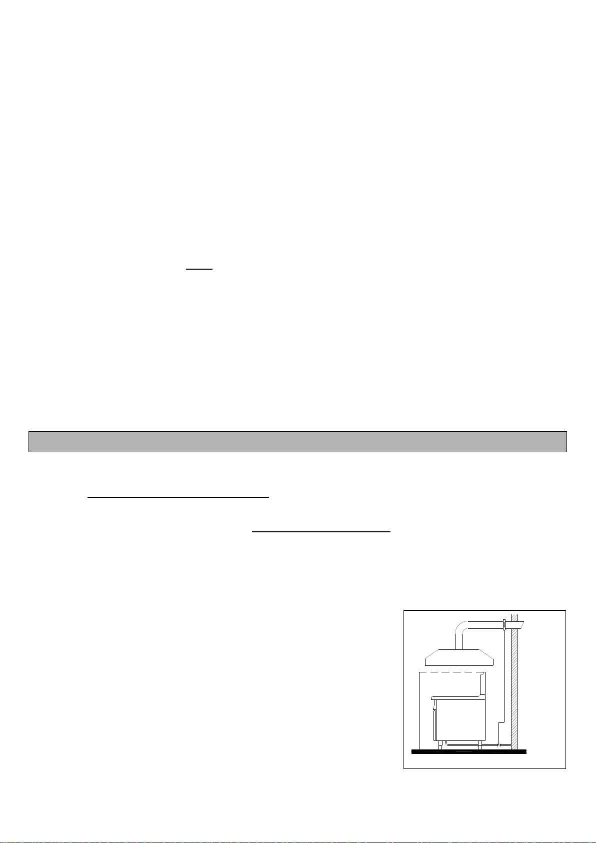
2.3 Scarico fumi
Gli apparecchi devono essere installati in locali adatti per lo scarico dei prodotti della combustione che deve avvenire nel
rispetto di quanto prescritto dalle norme di installazione. Le nostre apparecchiature sono considerate (vedi tabella 1 dati
tecnici) come:
APPARECCHI A GAS DI TIPO “A1”

4
Gli apparecchi di tipo A1 devono essere installati in locali sufficientemente ventilati per prevenire la concentrazione di
Gli apparecchi di tipo A1 non necessitano del collegamento diretto ad un condotto di scarico dei prodotti di combustione.
I prodotti della combustione però devono essere convogliati in apposite cappe o
dispositivi similari, collegate ad un camino di sicura efficienza oppure direttamente
mpiego di un aspiratore di aria collegato direttamente
in ambiente esterno, di portata non minore di quanto richiesto, che poi va
secondo le norme in vigore, indicativamente per un totale di 35 m³/h per ogni kW
di potenza gas installata.
Evacuazione forzata sotto cappa. Nel caso di installazione sotto cappa, la parte
dalla superficie di appoggio dell
condotti di scarico dei prodotti della combustione deve essere disposta entro il
tema di evacuazione
forzata, e deve interrompersi nel caso che la portata di questo scenda sotto i valori
deve potersi fare solo manualmente.
2.4 Collegamento gas
Controllar
di gas disponibile.
Controllare con i dati riportati sulla targhetta tecnica, che la portata del riduttore di pressione sia sufficiente per
hio. Si consiglia di montare un filtro a gas a monte
del regolatore di pressione al fine di garantire un funzionamento ottimale.
2.5 Collegamento elettrico
zione senza presa,
oppure anche senza cavo. Un collegamento corretto deve rispettare le norme in vigore e deve essere effettuato collegando
una presa normalizzata al cavo, sapendo che il filo giallo-verde è il conduttore di terra. Desiderando un collegamento diretto
al
carico, i cui contatti abbiano una distanza minima di apertura di 3 mm. Il cavo di terra giallo-verde non deve essere interrotto
NOTE: Il tipo di cavo di collegamento è indicato nella TABELLA 3.
La morsettiera di alimentazione è posizionata sotto il pannello destro della cucina.
EQUIPOTENZIALE
nziale.
1,8 mt
Fig. 1
Fig. 2

5
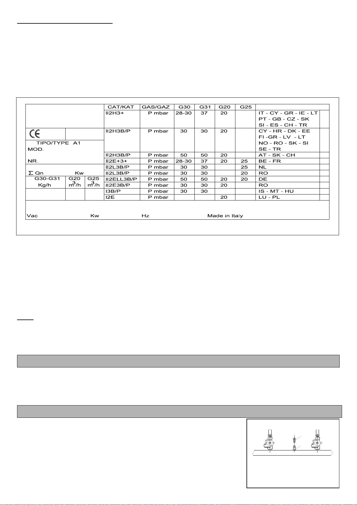
3. CARATTERISTICHE TECNICHE (Relative alla parte GAS)
rno.
-Apparecchio di categoria II2h3+
--G31) 28-30/37mbar
4. FUNZIONAMENTO CON GAS D’ALIMENTAZIONE IDENTICO A QUELLO PREDISPOSTO
Controllare se le indicazioni sulla targhetta segnaletica corrispondono al gas distribuito. Verificare, inoltre, la corrispondenza
di quanto qui di seguito riportato.
ATTENZIONE: Se il valore della pressione di alimentazione misurato è esterno all’intervallo riportato in tabella 4
pag.32, non è possibile procedere all’installazione e bisogna informare l’ente erogatore del gas dell’anomalia della
rete.
chiudere il portello anteriore.
4.2 Regolazione dell’aria primaria
in tabella 2.
4.3 Regolazione della fiamma pilota
è corretto. Se ciò non si verifica,
occorre controllare che gli iniettori montati siano quelli giusti (vedi tabella 2).
4.4 Controllo del bruciatore principale
contrario bisogna controllare gli iniettori e la posizione de 2).
5. REGOLAZIONE PER FUNZIONAMENTO CON ALTRI TIPI DI GAS
Per eseguire tale operazione, ad esempio passare da gas naturali a gas liquidi,
bisogna cambiare gli iniettori dei bruciatori principali, quelli delle fiamme pilota e
regolare il by-pass del minimo (vedere tabella 2).
Tutti gli iniettori necessari alla regolazione sono forniti contenuti in un sacchettino
principali sono marchiati in
centesimi di mm, mentre quelli della fiamma pilota hanno un numero di riferimento.
5.1 Sostituzione degli iniettori della tuttapiastra
Sollevare la piastra (attenzione, è pesante), estrarre il pannello dei comandi
dopo aver levato le manopole.
5.1.1 Fiamma pilota (Fig. 4)
Se la fiamma pilota è stata regolata in modo corretto dovrà avvolgere la
Gori installati siano quelli
giusti (vedere tabelle 2).
Per la fiamma pilota non è necessaria la re.
5.1.2 Bruciatore principale tuttapiastra (Fig. 5)
izzato (vedi tabella 2).
Il bruciatore della tuttapiastra è ad aria fissa:
4.1 Controllo della pressione di alimentazione (Fig. 3)
La pressione di alimentazione può essere misurata a mezzo di manometro
con tu
-
-Posizionare il manometro.
-
in caso contrario accertarsi della causa.
-
B
A
Fig. 3
Fig. 4
Fig. 5

6
5.1.3 Regolazione dei minimi (Fig. 6)
Togliere la manopola e regolare la fiamma in posizione minimo fino ad
ottenere una fiamma stabile ed uniforme; per la portata adatta vedere
tabella 2.
deve essere avvitata completamente.
5.2 Sostituzione degli iniettori dei bruciatori fuochi aperti
Estrarre le griglie, le bacinelle raccogli gocce, il corpo e la testa dei bruciatori.
5.2.1 Fiamma pilota (Fig. 7)
Se la fiamma pilota è stata regolata in modo corretto dovrà avvolgere la
ntrollare che gli iniettori installati siano quelli
giusti (vedere tabella 2).
5.2.2 Bruciatore principale (Fig. 8)
ta la stabilità delle
fiamme, cioè se non compaiono stacchi di fiamma con bruciatore freddo e se
non si verifica ritorno di fiamma con bruciatore caldo.
piano di cottura, è mostrata nella figura 9 ed indicata nelle tabelle 2. Svitare
5.2.3 Regolazione dei minimi (Fig. 6)
Togliere la manopola e regolare la fiamma in posizione minimo fino ad
ottenere una fiamma stabile ed uniforme; per la portata adatta vedere tabella
2.
avvitata completamente.
5.3 Sostituzione dell’iniettore del forno
Estrarre il fondo del forno.
5.3.1 Fiamma pilota (Fig. 4)
Se la fiamma pilota è stata regolata in modo corretto dovrà avvolgere la
che gli iniettori installati siano quelli
giusti (vedere tabella 2).
5.3.2 Bruciatore principale (Fig. 10)
Dopo aver effettuato la conversione bisogna applicare sulla targhetta (fig. 2),
utilizzato.
6. ACCESSIBILITÁ E SMONTAGGIO DEI PEZZI (solamente per l’installatore abilitato)
6.1 Valvola gas del forno
Svitare le due viti di fissaggio e togliere il pannello davanti sul lato destro, disinnestando i perni di fissaggio.
Svitare i dadi dei condotti del gas così come quello della termocoppia, estrarre il sensore di temperatura dalla sua
Con una chiave, svitare le due viti che fissano la valvola del gas.
Montare la nuova valvola.
6.2 Rubinetto gas dei bruciatori della tuttapiastra e del piano di cottura
Disinnestare i 4 perni che fissano il pannello dei comandi e toglierlo.
Svitare i dadi dei condotti del gas, della termocoppia così come quelli che fissano il rubinetto alla rampa di
alimentazione.
Montare il nuovo rubinetto.
Fig. 7
Fig. 8
Fig. 9
Fig. 10
Fig. 6
Fig. 11
7
6.3 Candela di accensione del forno
Togliere il fondo del forno.
Svitare i dadi di fissaggio della candela di accensione.
Estrarre la candela.
Scollegare il cavo della candela.
Montare la nuova candela.
6.4 Commutatore e termostato del forno elettrico o dell’armadio
Svitare le due viti di fissaggio e togliere il pannello sul lato destro del
Tutti i componenti sono visibili.
6.5 Resistenze del forno
Togliere il fondo del forno.
Togliere il pannello sul lato destro della cucina, svitando le due viti di fissaggio.
Svitare le viti di fissaggio della resistenza.
Cambiare la resistenza.
6.6 Resistenze dell’armadio
Togliere il pannello davanti la resistenza svitando le due viti visibili.
Cambiare la resistenza.
7. ISTRUZIONI D’USO
professionale.
7.1 Accensione e spegnimento
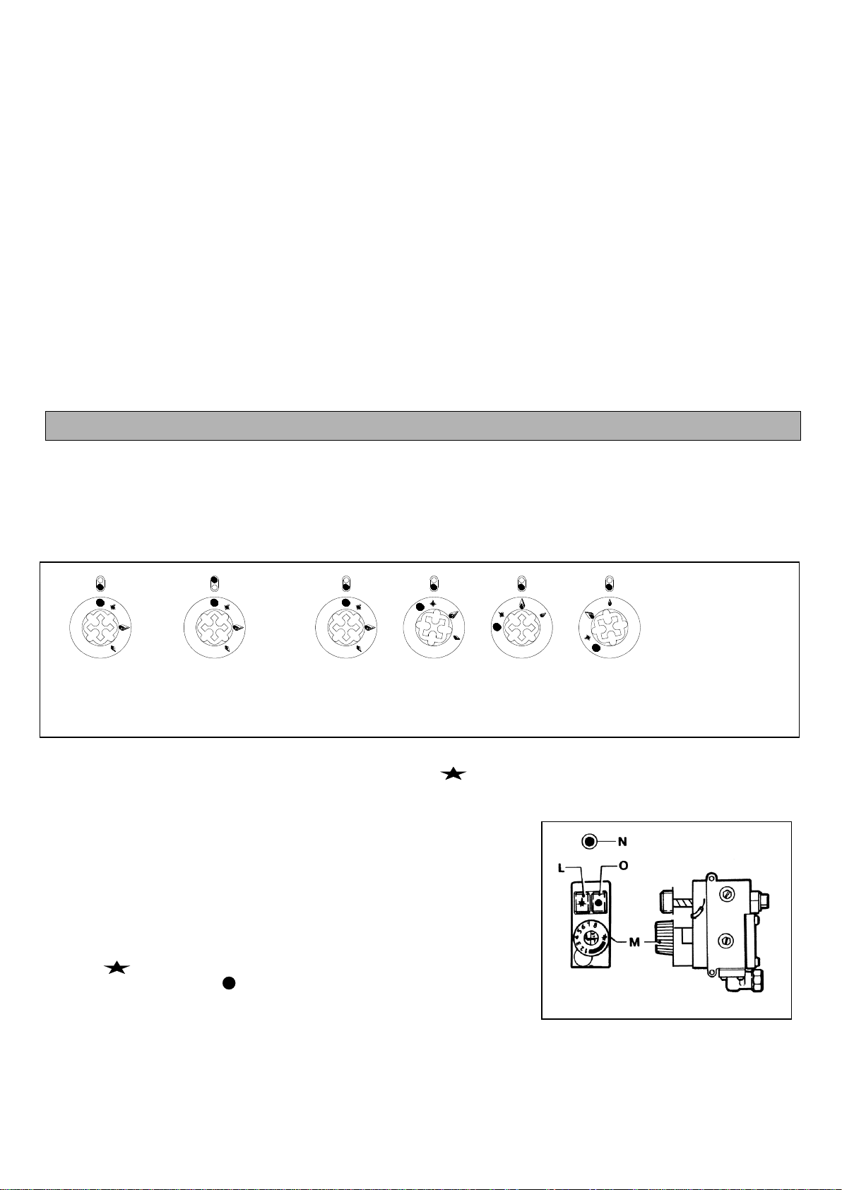
7.1.1 Tuttapiastra e fuochi vivi (Fig. 11)
7.1.1.1 Accensione della fiamma pilota
Premere sulla manopola e girarla verso sinistra sulla posizione . Tenere la manopola premuta ed allo stesso tempo
avvicinare un fiammifero acceso alla fiamma pilota; dopo avere acceso la fiamma pilota, mantenere premuta a fondo la
7.1.1.2 Accensione del bruciatore principale
Per accendere il bruciatore principale, girare la manopola verso sinistra sulla
portata calorica desiderata per la cottura.
7.1.1.3 Spegnimento
Per spegnere il bruciatore principale, girare la manopola verso destra sulla
posizione ; resterà accesa solo la fiamma pilota. Se si continua a girare la
manopola fino alla posizione , anche la fiamma pilota si spegnerà.
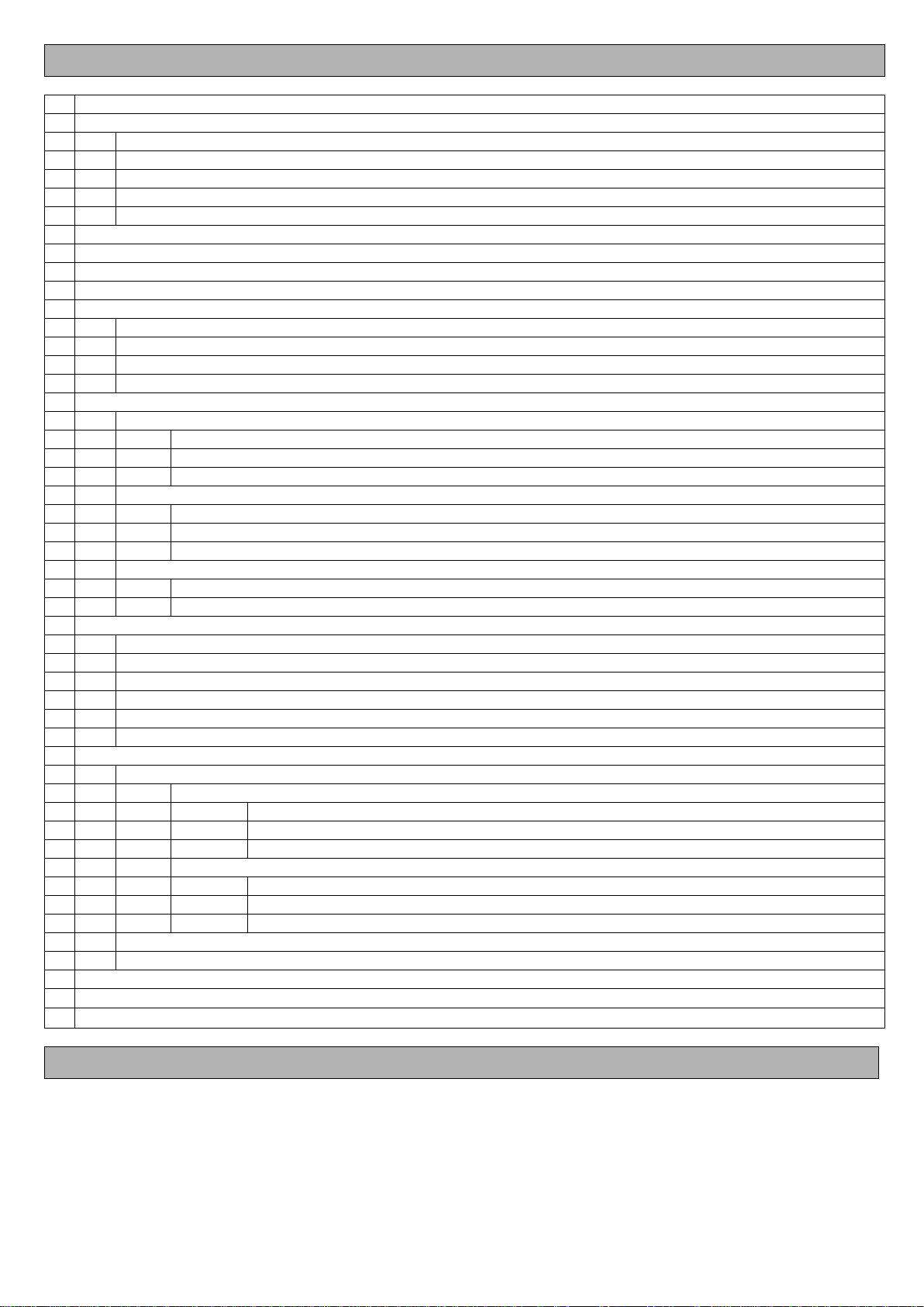
7.1.2 Bruciatore del forno (Fig. 12)
7.1.2.1 Accensione della fiamma pilota
tempo pigiare più volte il pulsa
Bruciatore
Anteriore Posteriore
Bruciatore 1 2 3 4
1 Spento
2 Pilota
3 Max
4 Min
Fig. 11
Fig. 12

8
Tenere il pulsante di accensione premuto a fondo per qualche istante al fine di permettere che la termocoppia si scaldi,
pulsante di accensione, la fiamma pilota dovesse spegnersi è n
7.1.2.2 Accensione del bruciatore principale e regolazione della temperatura
temperatura di cottura
desiderata; la manopola del termostato è numerata da 1 a 8:
-n. 1 = 100°; n. 2 = 135°; n. 3 = 170°; n. 4 = 200°; n. 5 = 235°; n. 6 = 270°; n. 7 = 300°; n. 8 = 340°
gnimento
automatici del bruciatore principale (regolazione acceso-spento, non esiste
minimo). Se la manopola del termostato viene ruotata verso destra fino al
punto di arresto, il bruciatore principale si spegne e resta accesa solo la
fiamma pilota.
7.1.2.3 Spegnimento del forno
secondo.
7.2 Armadio caldo elettrico (Fig. 13)
I modelli .TPG..C.. sono previsti di armadio caldo con riscaldamento elettrico.
Il loro uso è molto semplice:
-
- a, la quale si
Per spegnere :
riportare alla posizione “zero” la manopola “Q” premere il pulsante “P”
che si spegnerà.
7.3 Forno elettrico
Le resistenze sono posizionate nel cielo (calore superiore) e sotto la camera (calore inferiore).
La regolazione della temperatura tra i 50 ed i 280°C è ottenuta per mezzo di due termostati che controllano
e e la regolazione della temperatura, girare la manopola del termostato
sulla posizione della temperatura desiderata.
ATTENZIONE
Un termostato di sicurezza può spegnere la resistenza superiore (nel cielo) in caso di errato funzionamento. In caso di
FUNZIONAMENTO (Fig. 14):
ensione.
desiderata questa si spegne. Al reinserirsi delle resistenze si riaccende.
P
ATTENZIONE: Non appoggiare teglie sulla base del forno.
8. MANUTENZIONE
Ogni sera, a f
re tutte le parti estraibili del forno e lavarle
separatamente.
La pulizia delle parti in acciaio deve essere fatta accuratamente, utilizzando acqua tiepida. Se utilizzate del sapone, oppure
iaio
INOX.
one del gas. In caso di
chiamare il servizio tecnico.
Tutte le operazioni di manutenzione e di riparazione devono essere effettuate da un installatore abilitato.
Fig. 13
50
100
150
200
250
300
U
T
S
Fig. 14
9
CONTENTS
1.
GENERAL INSTRUCTIONS
Pag. 9
2.
INSTALLATION
Pag.10
2.1
Installation of the appliance
Pag.10
2.2
Installation
Pag.10
2.3
Fumes extraction
Pag.10
2.4
Connecting up gas
Pag.11
2.5
Electrical connection
Pag.11
3.
TECHNICAL FEATURES
Pag.11
Table 1 (gas consumption) S.700s and 900s
Pag.30
Table 2 (S.700s and 900s burners technical features)
Pag.31
Table 3 (Hotplate ranges S.700s e 900s)
Pag.30
4.
OPERATION WITH SUPPLY GAS IDENTICAL TO THAT AVAILABLE
Pag.11
4.1
Checking the supply pressure
Pag.11
4.2
Regulating the primary air
Pag.12
4.3
Regulating the pilot flame
Pag.12
4.4
Checking the main burner
Pag.12
5.
REGULATION FOR OPERATION WITH OTHER TYPES OF GAS
Pag. 12
5.1
Replacing the injectors of the hotplate ranges
Pag. 12
5.1.1
Pilot flame
Pag. 12
5.1.2
Main burner
Pag. 12
5.1.3
Regolating the minimums
Pag. 12
5.2
Replacing the injectors of the main burner naked flames
Pag. 12
5.1.1
Pilot flame
Pag. 12
5.1.2
Main burner
Pag. 12
5.1.3
Regolating the minimums
Pag. 12
5.2
Replacing the oven injector
Pag. 12
5.2.1
Pilot flame
Pag. 12
5.2.2
Main burner
Pag. 13
6.
ACCESSIBILITY AND DISASSEMBLY OF THE PARTS
Pag. 13
6.1
Oven gas valve
Pag. 13
6.2
Gas cock of the hob burners
Pag. 13
6.3
Oven igniter plug
Pag. 13
6.4
Switch and thermostat of the electric oven or of the cabinet
Pag. 13
6.5
Oven resistors
Pag. 13
6.6
Cabinet resistors
Pag. 13
7.
OPERATING INSTRUCTIONS
Pag. 14
7.1
Lighting and turning out
Pag. 14
7.1.1
Hotplate and naked flames
Pag. 14
7.1.1.1
Lighting the pilot flame
Pag. 14
7.1.1.2
Lighting the main burner
Pag. 14
7.1.1.3
Turning out
Pag. 14
7.1.2
Oven burner
Pag. 14
7.1.2.1
Lighting the pilot flame
Pag. 14
7.1.2.2
Lighting the main burner and regulating the temperature
Pag. 14
7.1.2.3
Turning out the oven
Pag. 14
7.2
Electric warm cabinet
Pag. 14
7.3
Electric oven
Pag. 15
8.
MAINTENANCE
Pag. 15
Wiring diagram of the hot cupboard
Pag. 32
Wiring diagram of the oven
Pag. 33
1. GENERAL INSTRUCTIONS
Read the instructions contained in this handbook carefully as they give important advice concerning safety of installation,
use and maintenance.
Keep this handbook for any further consultation by the various operators.
After having removed the packing, make sure the equipment is intact. In case of doubt, do not use the equipment and
contact professionally qualified staff.
Before connecting the equipment, make sure that the rating corresponds to that of the gas and electricity mains.
The equipment must only be used by staff trained in use of the same.
Before carrying out cleaning and maintenance, disconnect the equipment from the electricity and/or gas supply system.
10
Switch the equipment off in the case of a fault or malfunctioning. For any repairs only contact an authorised technical service
centre and request the use of original spare parts.
Failure to observe the above may jeopardise safety of the equipment.
Connection, installation of the system and appliances, ventilation and fumes extraction must be carried out according to the
The electrical safety of this equipment is only ensured when it is correctly connected to an effective earthing system as laid
down by current electrical safety regulations.
This fundamental safety requirement has to be checked and, in case of doubt, an accurate check on the system by
professionally qualified staff requested. The manufacturer cannot be considered liable for any damage caused by failure to
earth the system.
This equipment must only be used for the purpose for which it was specifically designed.
Do not wash the equipment with direct, high pressure jets of water.
Do not obstruct the openings or vents for extraction or release of heat.
So as to avoid the risk of rust or chemical attack in general, the stainless steel surfaces have to be kept properly clean.
Clean the parts in stainless steel daily with warm, soapy water, then rinse thoroughly and dry carefully.
On no account should the stainless steel be cleaned with steel wool pads, brushes or scrapers in standard steel, in that
they could deposit ferrous particles which, by oxidising, cause rust spots. Stainless steel wool can, if necessary, be used
in the direction of the satin finish.
Should the equipment not be used for long periods, close the gas valve and wipe all the steel surfaces vigorously with a
cloth moistened with Vaseline oil in order to apply a protective layer; also air the rooms periodically.
Before carrying out the connection, check on the technical data plate that the appliance has been tested and type-
approved for the type of gas available on the user’s premises.
Should the type of gas indicated on the plate not be that available, follow the instructions in the paragraph
“Conversion to different type of gas”.
The manufacturer of the appliance declines every responsibility for possible mistake contained in this booklet imputable to
printing or transcription errors. It also reserves the right to bring changes to the product if retains useful or necessary
without jeopardizing the essential characteristics.
The manufacturing company declines any and every responsibility if the rules brought in this manual are not strictly
observed.
The manufacturer of the appliance declines all responsibility for damage caused by faulty installation, tampering with the
appliance, improper use, poor maintenance, failure to observe local regulations and unskilled use.
THE DISCHARGE OF MACHINE WHEN NO MORE OF USE MUST BE DONE IN COMPLIANCE WITH LAW. THE
MACHINE MUST BE DELIVERED TO FIRM AUTHORIZED FOR THE DISCHARGE OF MACHINE AND OF ITS
COMPONENTS.
2. INSTALLATION
2.1 Installation of the appliance
The operations of installation, any conversion for use with other types of gas, start-up and the remedying of any faults in
the systems, must only be carried out by qualified staff, in accordance with current laws.
The gas and electrical systems and the rooms where the appliances are installed must fulfil the regulations existing in the
various areas and in particular consideration must be made of the fact that the air required for combustion of the burners is
equal to 2 m3/h per kW of installed power and that accident prevention regulations must be observed.
2.2 Installation
Remove the appliances from the packing and position them in the place of use, levelling them and regulating their height
by means of the adjustable feet or other means.
Remove the protective film from the external panels, detaching it slowly to prevent the glue from remaining.
It is important that the walls adjacent to the appliance are protected against the heat. Place refractory sheets in between
them place the appliances at least 200 mm away from the side or rear walls.
2.3 Fumes extraction
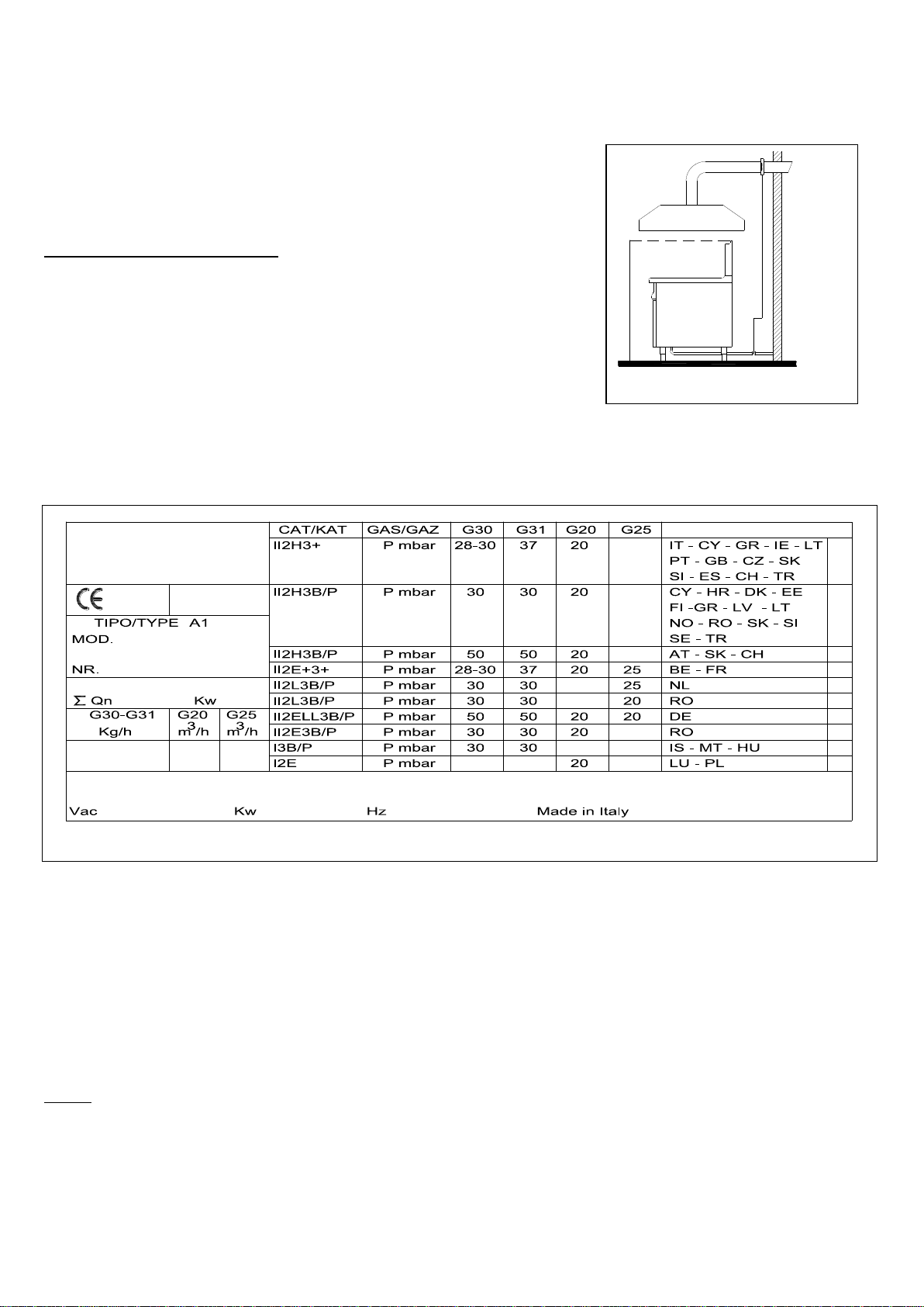
The appliances must be installed in rooms suitable for the extraction of combustion
products, in accordance with the provisions of the installation instructions. Our
equipment is considered (see specifications table) as:
“A1” TYPE GAS APPLIANCES
The A type appliances must be installed in sufficiently ventilated places in order to
prevent the concentrations of harmful substances in the room where the unit is
installed. They are not designed to be connected to a discharge line of combustible
materials. These appliances must discharge the combustible products into the
appropriate hoods, or similar devices, connected to a flue of proven efficiency, or
they may be connected directly to an outdoor vent. Failing this, the use of an
extractor fan is permitted, connected directly to an external area, with sufficient
capacity, which will then be increased by the exchange of air necessary for the
welfare of the workers under current regulations, approximately 35 m³/h for each kW of gas power installed.
1,8 mt
Fig. 1
11
Forced fume evacuation under hood
floor on which the appliance stands (the ground), and the mouth of the combustion fume pipe must be inside the same
extractor hood (Fig. 1
be cut out in the event its capacity falls below that required by the law in force. It should only be possible to restore the
appli
2.4 Connecting up gas
Check on the rating plate (Fig. 2), under the fires on the left-hand side, that the appliance has been tested and approved
for the type of gas that the user uses.
Check that the nozzles on the appliance are suitable for the available gas supply.
Check on the rating plate that the pressure reducer is adequate
If gas supply pressure deviates by more than 10% from nominal pressure, fit a pressure regulator upstream of the appliance
to ensure that nominal pressure is maintained.
Do not reduce the diameter of the pipe between the reducer and the appliance.
Fit a gas filter upstream of the pressure regulator in order to optimise operating efficiency.
2.5 Electrical connection
The appliances in the series .TPG..C... or .TPG..FE are delivered with a power cable without a plug or even without a cable.
A correct connection must observe the laws in force and must be carried out by connecting a standardised plug to the cable,
knowing that the yellow-green wire is the earth wire. If a direct connection to the mains is required, an omnipolar switch has
to be installed between the appliance and the mains. The switch is to be dimensioned for the load and its contacts must
have a minimum opening distance of 3 mm. The yellow-green earth wire must not be interrupted by the switch.
NOTE: the type of connection cable is indicated in TABLE 3.
The supply terminal board is positioned under the right-hand panel of the cooker.
UNIPOTENTIAL
The appliance must be connected to a unipotential system.
The terminal provided is situated at the rear, near the cable inlet, and is marked by a label.
3. TECHNICAL FEATURES (Relating to the GAS part)
The data plate is located on the base of the cabinet or on the panel under the oven.
- Appliance in category
- Supply pressure: Butane/Propane (G30-G31) 28-30/37mbar
4. OPERATION WITH SUPPLY GAS IDENTICAL TO THAT AVAILABLE
Check whether the indications on the data plate correspond to the gas distributed.
Also check the correspondence of what is indicated below.
4.1 Checking the supply pressure (Fig. 3)
The supply pressure must be measured by means of a pressure gauge with
a U-shaped pipe or of the electronic type with minimal grading of 0.1 mbar.
-
- Position the pressure gauge.
B
A
Fig. 3
Fig. 2
12
- Switch on the appliance and check whether the pressure is the one
intended: if not check on the cause.
- At the end of the operation, reassemble the appliance and check on the
connection.
ATTENTION: If the pressure measurement is not within the thresholds stated in table 4 at page 32, instead of
installing the appliance you should contact your gas provider to report a fault with your mains supply.
Close the gas valve, disconnect the pressure measurement device, do up the screw you had previously undone and
close the front panel.
4.2 Regulating the primary air
The primary air must be regulated taking into account the indications of table 2.
4.3 Regulating the pilot flame
Regulate and check that the flame envelops the thermocouple and that the appearance of the same is correct. If this is not
the case, check that the injectors mounted are the right ones (see table 2).
4.4 Checking the main burner
Switch on the appliance and check that the flame, lighting and regulation of the minimum are correct. Otherwise the injectors
and the position of the primary air have to be checked (see table 2).
5. REGULATION FOR OPERATION WITH OTHER TYPES OF GAS
To carry out this operation, for example in order to change from natural to liquid gases, the injectors of the main burners
and of the pilot flames have to be changed and the by-pass of the minimum regulated (see tables 2).
All the injectors required for regulation are supplied in a small bag together with the appliance. The injectors of the main
burners are marked in hundredths of a millimetre, while those of the pilot flame have a reference number.
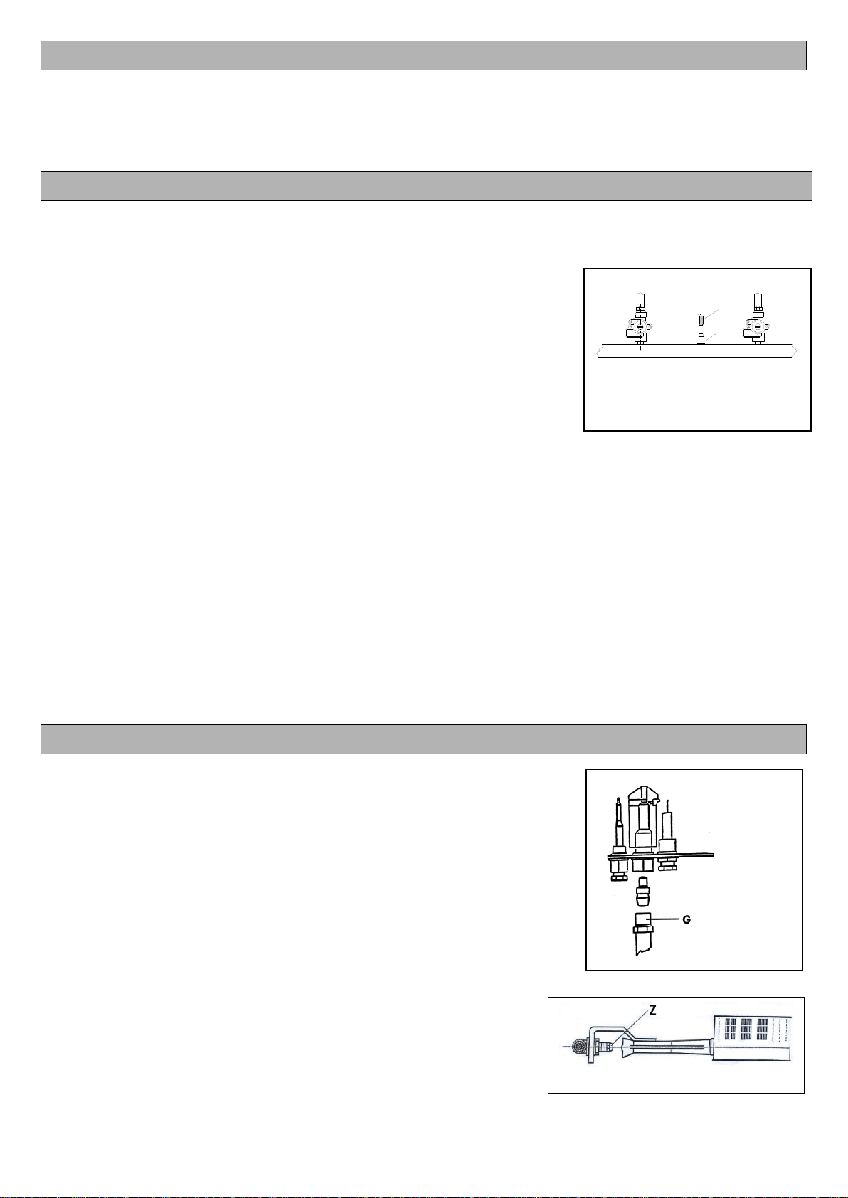
5.1 Replacing the injectors of the hotplate ranges
Lift the plate (attention it is heavy), take out the control panel after removing
the knobs.
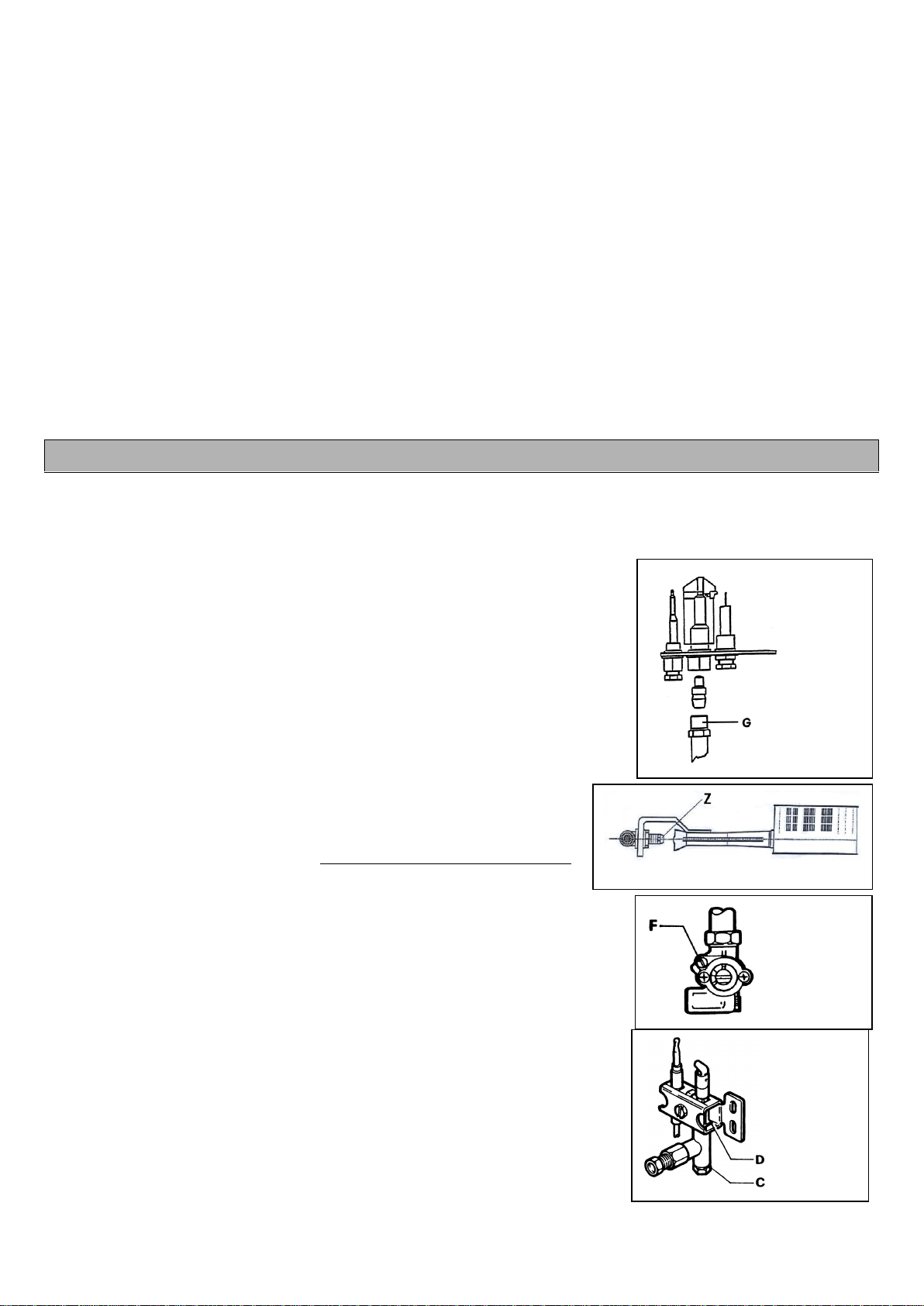
5.1.1 Pilot flame (Fig. 4)
If the pilot flame has been regulated correctly it should envelop the
thermocouple and have a perfect exterior appearance. If this is not the
the right ones (see table 2).
Regulation of the primary air is not necessary for the pilot flame.
5.1.2Main burner (Fig. 5)
e suitable for the type
of gas used (see table 2).
The solid top burner is with fixed air: the air does not have to be regulated.
5.1.3Regulating the minimums (Fig. 6)
Remove the knob and regulate the flame to the minimum setting until a
stable and even flame is obtained. For the suitable capacity see tables 2.
unscrewed.
5.2 Replacing the injectors of the main burners naked flames
Remove the grilles, drip collector basins, body and head of the burners.
5.2.1 Pilot flame (Fig. 7)
If the pilot flame has been regulated correctly, it should envelop the
thermocouple and have a perfect exterior appearance. If this is not the case,
stalled are the right ones
(see tables 2).
Fig. 7
Fig. 6
Fig. 4
Fig. 5

13
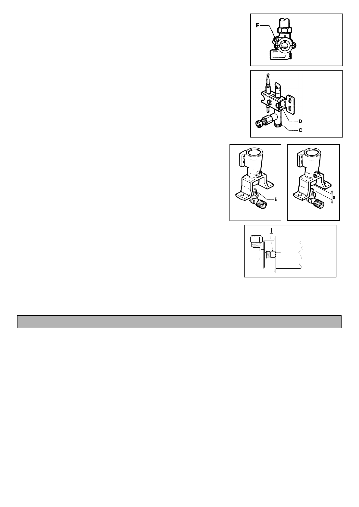
5.2.2 Main burner (Fig. 8)
The primary air is regulated correctly if the stability of the flames is ensured,
i.e. if flame lifts do not appear with the burner cold and if there is no flame
return with the burner hot.
The distance foreseen for regulation of the primary air, for the burners of the
hob and of the oven, is shown in Figures 9 and indicated in table 2. Unscrew
with a 11 mm spanner and mount the appropriate injector.
5.2.3 Regulating the minimums (Fig. 6)
Remove the knob and regulate the flame to the minimum setting until a stable
and even flame is obtained. For the suitable capacity see table 2.
5.3 Replacing the oven injector
Remove the base of the oven.
5.3.1 Pilot flame (Fig. 4)
If the pilot flame has been regulated correctly, it should envelop the thermocouple and have a perfect exterior
(see table 2).
Regulation of the primary air is not necessary for the pilot flame.
5.3.2 Main burner (Fig. 10)
6. ACCESSIBILITY AND DISASSEMBLY OF THE PARTS (only for qualified installers)
6.1 Oven gas valve
Unscrew the two attachment screws and remove the front right-hand panel, disengaging the attachment pins.
Unscrew the nuts of the gas pipes and that of the thermocouple, remove the temperature sensor from its position inside
the oven chamber and disconnect the wire of the battery lighting device.
Using a spanner, unscrew the two screws which attach the gas valve.
Mount the new valve.
6.2 Gas cock of the hob burners
Disengage the 4 pins which attach the control panel and remove it.
Unscrew the nuts of the gas pipes and that of the thermocouple and those which attach the gas cock to the gas ramp.
Mount the new gas cock.
6.3 Oven igniter plug
Remove the base of the oven.
Unscrew the attachment nuts of the igniter plug.
Remove the plug.
Disconnect the igniter plug wire.
Mount the new plug.
6.4 Switch and thermostat of the electric oven or of the cabinet
Unscrew the two attachment screws and remove the panel on the right hand-side of the oven, or the lower panel of the
cabinet.
All the components are on view.
6.5 Oven resistors
Remove the base of the oven.
Remove the panel on the right-hand side of the cooker, unscrewing the two attachment screws.
Unscrew the screws attaching the resistor.
Change the resistor.
6.6 Cabinet resistors
Remove the lower panel of the cabinet.
Remove the panel in front of the resistor by unscrewing the two visible screws.
Change the resistor.
Fig. 8
Fig. 9
Fig. 10
14
7. OPERATING INSTRUCTIONS
The appliance must be adopted by qualified staff, as it is intended solely for professional catering.
7.1 Lighting and turning out
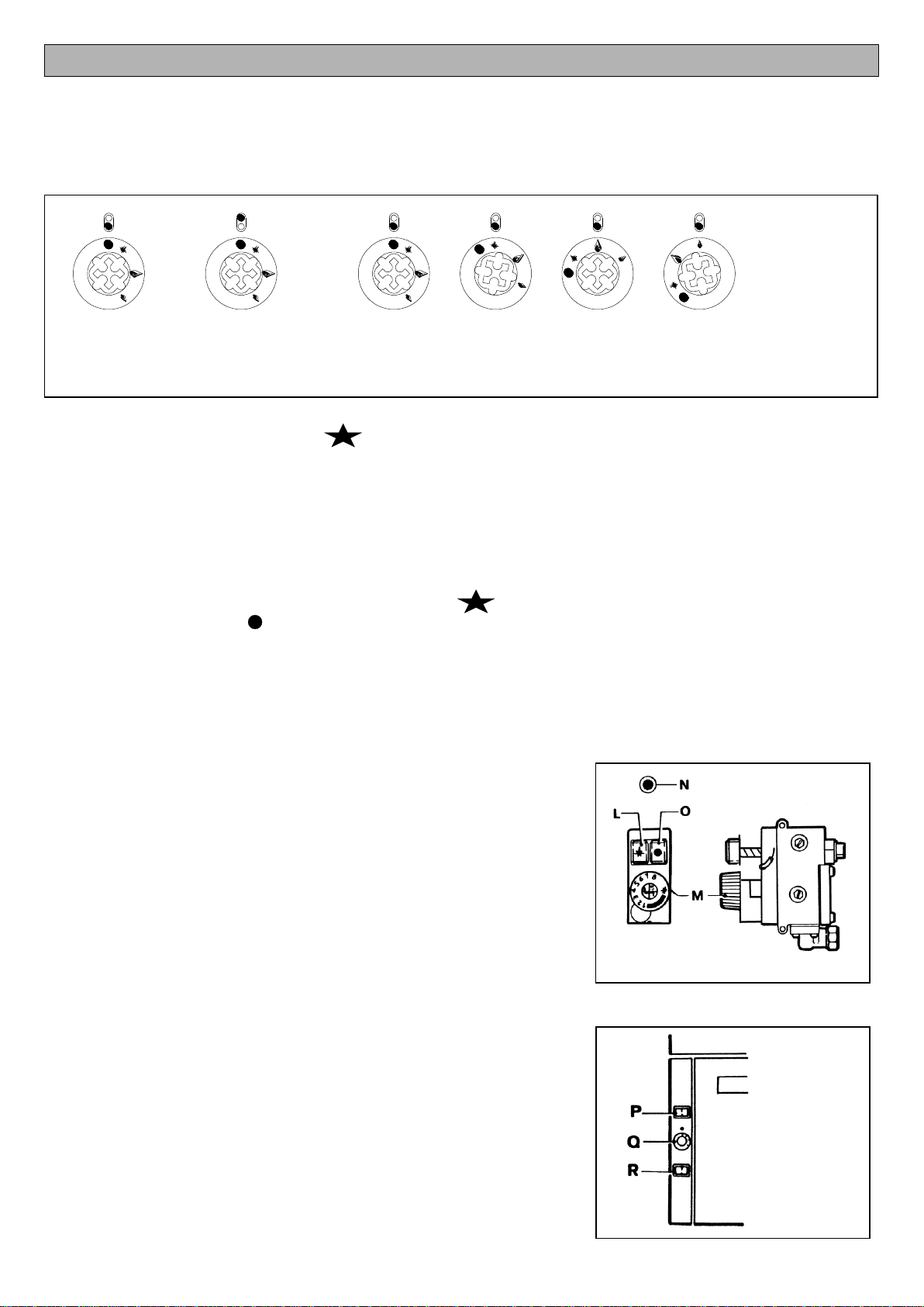
7.1.1 Hotplate and naked flames (Fig. 11)
7.1.1.1 Lighting the pilot flame
Press on the knob and turn it left to the setting. Keep the knob fully pressed and at the same time bring a lighted
match near the pilot flame. After having lit the pilot flame keep the knob fully pressed to allow the thermocouple to heat.
Should the pilot flame go out repeat the operation.
7.1.1.2 Lighting the main burner
In order to light the main burner turn the knob left to the "maximum" setting (large flame) or directly to the "minimum" setting
(small flame). Between these two settings it is possible to select the heat capacity required for cooking.
7.1.1.3 Turning out
In order to turn out the main burner turn the knob right to the setting. Only the pilot flame will remain lit. By continuing
to turn the knob as far as the setting, the pilot flame will also go out.
7.1.2 Oven burner (Fig. 12)
7.1.2.1 Lighting the pilot flame
Turn the knob of the thermostat right as far as the stop. Press the lighting button "L" and at the same time press the button
"N" taking a stack several times. Keep the lighting button fully pressed for a few moments in order to allow the thermocouple
to heat, then release it. The pilot flame can be observed through the appropriate spyhole. If, after having released the
lighting button, the pilot flame were to go out, the operation has to be repeated.
7.1.2.2 Lighting the main burner and regulating the temperature
With the pilot flame lit, turn the knob of the the
required cooking temperature. The knob of the thermostat is numbered from
1 to 8:
-n. 1 = 100°; n. 2 = 135°; n. 3 = 170°; n. 4 = 200°;
-n. 5 = 235°; n. 6 = 270°; n. 7 = 300°; n. 8 = 340°
Regulating the thermostat entails automatic lighting and turning out of the
main burner (on-off regulation, there is not minimum). If the thermostat knob
is turned right as far as the stop, the main burner goes out and only the pilot
flame remains lit.
7.1.2.3 Turning out the oven
In order to turn out the pilot flame and also prevent lighting of the main burner, press the off button "O" down. The safety
device installed prevents relighting of the appliance for a few seconds.
7.2 Electric warm cabinet (Fig. 13)
The models .TPG..C... are provided with a warm cabinet with electric heating.
They are very simple to use.
-
-
automatically regulated, indicating that heating has taken place by the
pilot light "R" (blinking).
In order to turn it out:
-return the knob "Q" to the zero setting press the button "P" which will go
out.
Riar
BurnerBurner
Front 1 2 3 4 Min
3 Max
2 Pilot
1 Off
4
Fig. 11
Fig. 12
Fig. 13

15
7.3 Electric oven
The resistors are positioned in the ceiling (higher heat) and under the chamber (lower heat). The temperature is regulated
between 50 and 280¡C by means of two thermostats which control the resistors independently. In order to light the oven
and regulate the temperature turn the knob of the thermostat to the required temperature setting.
CAUTION: Before starting maintenance work, remove the pilot light or disconnect the switch placed upstream.
A safety thermostat can turn out the higher resistor (in the ceiling) in the event of malfunctioning. In the event of faulty
working switch the appliance off and call the service centre.
OPERATION (Fig. 14):
The pilot light "S" lights, indicating that power is supplied to the appliance.
Turn the thermostat "U" to the required temperature.
n as the
required temperature is reached it goes out. When the resistors are newly
actuated it lights again.
In order to switch off the appliance turn the knobs to the initial setting.
CAUTION: Never place trays on the oven floor.
8. MAINTENANCE
We recommend signing a contract for maintenance at least once a year.
Every evening, at the end of work, the appliance must be cleaned thoroughly. Daily cleaning of the appliance guarantees
perfect working and longer life of the appliance itself.
Before starting cleaning disconnect the appliance from the mains; remove all the removable parts of the oven and wash
them separately.
During cleaning do not wash the appliance with direct or pressurised jets of water!
The steel parts must be cleaned thoroughly, using warm water. If soap or another detergent is used make sure that they
do not contain abrasive products and that they are recommended for cleaning stainless steel.
If the appliance is not used for a certain period of time, close the gas supply cock. In the case of a fault in the appliance, or
malfunctioning, close the main gas inlet cock and call the service centre.
All maintenance and repair work must be carried out by a qualified installer.
50
100
150
200
250
300
U
T
S
Fig. 14
16
SOMMAIRE
1.
AVERTISSEMENTS GENERAUX
Pag.16
2.
INSTALLATION
Pag.17
2.1
Pag.17
2.2
Pose des appareil
Pag.17
2.3
Evacuation des fumees
Pag.17
2.4
Raccordement du gaz
Pag.18
2.5
Branchement électrique
Pag.18
3.
CARACTÉRISTIQUES TECHNIQUES
Pag.19
Tableau 1 (consommation de gaz) S.700s et 900s
Pag.31
Tableau 2 (caracteristiques techniques brûleur S.700s et 900s)
Pag.30
Tableau 3 (coup-de-feu S.700s et 900s)
Pag.31
4.
FONCTIONNEMENT AVEC LE MÊME GAZ QUE LE GAZ DISPONIBLE
Pag.19
4.1
tation
Pag.19
4.2
Pag.19
4.3
Réglage de la veilleuse
Pag.19
4.4
Contröle du brûleur principal
Pag.19
5.
RÉGLAGE POUR FONCTIONNEMENT AVEC D’AUTRES TYPES DE GAZ
Pag.19
5.1
Remplacement des injecteurs des brûleurs de la plaque coup-de-feu
Pag. 19
5.1.1
Veilleuse
Pag. 19
5.1.2
Brûleur principal coup-de-feu
Pag. 19
5.1.3
Réglage des minimums
Pag. 20
5.2
Remplacement des injecteurs des brûleurs principaux
Pag. 20
5.2.1
Veilleuse
Pag.20
5.2.2
Brûleur principal
Pag.20
5.2.3
Réglage des minimums
Pag.20
5.3
Changement des injecteurs du four
Pag.20
5.3.1
Veilleuse
Pag.20
5.3.2
Brûleur principal
Pag.20
6.
ACCESSIBILITÉ ET DÉMONTAGE DES PIÈCES
Pag.20
6.1
Valve gaz du four
Pag.20
6.2
Robinet gaz des brûleurs du plan de cuisson et coup-de-feu
Pag.20
6.3
Pag.20
6.4
Pag.21
6.5
Résistance du four
Pag.21
6.6
Pag.21
7.
MODE D’EMPLOI
Pag.21
7.1
Allumage et extinction
Pag.21
7.1.1
Coup-de-feu et feux vivs
Pag.21
7.1.1.1
Allumage de la veilleuse
Pag.21
7.1.1.2
Allumage du brûleur principal
Pag.21
7.1.1.3
Extinction
Pag.21
7.1.2
Brûleur du four
Pag.21
7.1.2.1
Allumage de la veilleuse
Pag.21
7.1.2.2
Allumage du brûleur principal et réglage de la température
Pag.22
7.1.2.3
Extinction du four
Pag.22
7.2
Armoire chauffante électrique
Pag.22
7.3
Four électrique
Pag.22
8.
ENTRETIEN
Pag.22
Schém
Pag.32
Schéma électrique du four
Pag. 33
1. AVERTISSEMENTS GENERAUX
Lire attentivement les avertissements contenus dans cette notice dans la mesure où ils indications
concernant la
Conserver cette notice de manière à ce que les différents opérateurs puissent la consulter à tout moment.
du personnel professionnellement qualifié.
é que par du personnel formé à cet effet.

17
et/ou gaz.
Le non-respect de ce qui est précisé ci-
Le raccordement, la mise en service de l’installation et des appareils, l’aération et l’évacuation des fumées doivent être
effectués, selon les instructions du constructeur, par du personnel professionnellement spécialisé, conformément aux
normes en vigueur.
La sécurité électrique de ce
conformément aux normes de sécurité électrique en vigueur.
Il est nécessaire de vérifier cette norme de sécurité fondamentale et, en cas de doute, demander un contrôle soigné de
Le constructeur décline toute responsabilité en cas de
dommages causés par le non-raccordement de l’installation à une prise de terre.
propres.
.
ier inox avec paillette, brosse ou racloir en acier ordinaire, dans la mesure où ils peuvent
dans le sens du satinage.
protection ; en
outre, aérer périodiquement les locaux.
Avant de procéder au raccordement, contrôler sur la plaque signalétique que l’appareil a été testé et homologué pour le
type de gaz disponible chez l’utilisateur.
Au cas où le type de gaz indiqué sur la plaque ne serait pas celui distribué, suivre les indications du paragraphe
La société constructrice décline toutes responsabilités pour les possibles inexactitudes contenues dans cet opuscule
imputable à erreurs de transcriptions ou imprimeries. Elle réserve le droit de apporter à ses produits les modifiques que
retienne utile ou nécessaires, sans préjudicier les caractéristiques essentielles.
La société constructrice décline toutes responsabilités au cas auquel les normes contenues dans cet opuscule ne soient
strictement respectées.
ropre, un mauvais entretien, par le non-respect des normes locales
CONCERNANT LE MATERIEL USAGE, VOUS DEVEZ VOUS METTRE EN CONFORMITE SELON LES NORMES EN
VIGUEUR. LE MATERIEL DOIT ETRE REMIS A UN ORGANISME AUTORISE A LA COLLECTE ET TRAITEMENT.
2. INSTALLATION
2.1 Installation de l’appareil
ne doivent être accomplies que par du personnel qualifié, conformément
aux normes en vigueur.
combustion des brûleurs est de 2 m3/h par kW de puissance installée et que les Normes pour la prévention des accidents
doivent être respectées.
2.2 Pose des appareil
Sortir les appar
Retirer des panneaux extérieurs la pellicule de protection en le déta
res
ou bien installer les appareils à au moins 200 mm des parois latérales ou arrières.
2.3 Evacuation des fumées
s techniques)
comme:
APPAREILS A GAZ DE TYPE “A1”
18
Les appareils de type A1 doivent etre installes dans des locaux suffisamment aeres pour prevenir la concentration de
nt pas prevus pour etre raccordes a
Ces appareils doivent evacuer les produits de la combustion a travers des hottes prevues a cet effet ou des dispositifs
En son absence, il est possible d'utiliser un aspirateur d'air directement raccordé
à l'extérieur, avec un débit non inférieur aux nécessités, et qui doit être ensuite
augmenté du renouvellement d'air nécessaire pour le bien-être des opérateurs
selon les normes en vigueur, indicativement pour un total de 35 m³/h pour chaque
kW de puissance de gaz installée.
Evacuation forcée sous la hotte. En cas d'installation sous une hotte,
l'extrémité du conduit d'évacuation de l'appareil doit se trouver à au moins
1,8 m de la surface d'appui de l'appareil (sol); la section de sortie des
conduits d'évacuation des produits de la combustion doit être placée dans
le périmètre de base de la hotte (Fig. 1). L'alimentation du gaz à l'appareil
doit être directement asservie au système d'évacuation forcée, et doit
s'interrompre au cas où le débit de celui-ci descend au-dessous des valeurs
prescrites par la norme d'installation. Le retour de l'alimentation du gaz à
l'appareil ne doit pouvoir s'effectuer que manuellement.
2.4 Raccordement du gaz
et homologué pour le type de gaz disponible dans les locaux de
Contrôler, sur les données reportées sur la plaquette technique, que le débit du réducteur de pression est suffisant pour
Eviter d’interposer des réduction de section entre le réducteur et l’appareil. Afin de garantir un fonctionnement
optimal, il est conseillée de monter un filtre à gaz en amont du régulateur de pression.
2.5 Branchement électrique
câble. Un branchement correct doit respecter les normes en vigueur et doit être effectué en branchant une prise normalisée
au câble, sachant que le fil jaune-vert est le conducteur de terre. Si vous souhaitez un branchement direct au réseau
,
dont les contacts ai-vert ne doit pas être interrompu
NOTE
Le bornier est installé sous le panneau droit de la cuisinière.
ÉQUIPOTENTIEL
1,8 mt
Fig. 1
Fig. 2
19
3. CARACTÉRISTIQUES TECHNIQUES (Relatives à la partie GAZ)
-Appareil de catégorie II2E+3+
--G31) 28-30/37mbars
Gaz
4. FONCTIONNEMENT AVEC LE MÊME GAZ QUE LE GAZ DISPONIBLE
Contrôler si les indications de la plaque signalétique correspondent au gaz distribué. Vérifier en outre la correspondance
de ce qui est reporté ci-dessous.
4.1 Contrôle de la pression d’alimentation (Fig. 3)
La pr
mbar.
-
- Positionner le manomètre.
- ier quelapressionsoitcelleprévue:dansle
cas contraire,envérifierla cause.
-
ATTENTION: si le valeur de la pression d'alimentation mesurée est en dehors de l'intervalle reporté dans le tableau 4 à
page 32, l'installation ne pourra pas être effectuée. Informer de l'anomalie sur le réseau, l'entreprise de distribution du gaz.
Fermer le robinet de sectionnement du gaz, débrancher le manomètre, revisser la vis de fermeture et refermer la
porte antérieure.
4.2 Réglage de l’air primaire
4.3 Réglage de la veilleuse
est correct.Sicelanesevérifiepas,contrôler
que les injecteurs montés soient ceux prévus (voir tableau 2).
4.4 Contrôle du brûleur principal
correct. Dans le cas contraire,
5. RÉGLAGE POUR FONCTIONNEMENT AVEC D’AUTRES TYPES DE GAZ
Pour accomplir cette opération, par exemple pour passer des gaz naturels à gaz
liquides, il faudra changer les injecteurs des brûleurs principaux, ceux des veilleuses
et régler le by-pass du minimum (voir tableaux 2).
Tous les injecteurs nécessaires au réglage sont fournis dans un sachet avec
s en centièmes de mm
tandis que ceux de la veilleuse ont un numéro de référence.
5.1 Remplacement des injecteurs des brûleurs de la plaque coup-de-feu
Enlever la plaque (faire attention, elle est lourd), enlever le panneau des
commandes après les manettes.
5.1.1 Veilleuse (Fig. 4)
Si la veilleuse a été réglée de manière correcte, elle devra envelopper le
prévus (voir tableaux 2).
5.1.2 Brûleur principal coup-de-feu (Fig. 5)
Dévisser l'injecteur Zet le remplacer par l'injecteur adapté au type de
gaz utilisé (voir tableau 2).
Les brûleurs du grill est a air fixe:
B
A
Fig. 3
Fig. 4
Fig. 5
20
5.1.3 Réglage des minimums (Fig. 6)
une flamme stable et uniforme; pour le débit adapté, voir tableau 2.
Pour le
complètement vissée.
5.2 Remplacement des injecteurs des brûleurs principaux
Extraire les grilles, les bacs de récolte des graisses, le chapeau et la tête des brûleurs.
5.2.1 Veilleuse (Fig. 7)
Si la veilleuse a été réglée de manière correcte, elle devra envelopper le
(voir tableau 2).
5.2.2 Brûleur principal (Fig. 8)
-à-c brûleur froid et
retour de flamme avec brûleur chaud.
de cuisson et du four, est montrée aux figures 9 et indiquée dans le tableau
5.2.3 Réglage des minimums (Fig. 6)
une flamme stable et uniforme ; pour le débit adapté, voir tableau 2.
complètement vissée.
5.3 Changement des injecteurs du four
Extraire la sole du four.
5.3.1 Veilleuse (Fig. 4)
Si la veilleuse a été réglée de manière correcte, elle devra envelopper le
5.3.2 Brûleur principal (Fig. 10)
6. ACCESSIBILITÉ ET DÉMONTAGE DES PIÈCES (réservé à l’installateur agréé)
6.1 Valve gaz du four
Dévisser les deux vis de fixation et retirer le panneau avant sur le côté droit, en déconnectant les chevilles de fixation.
Dévisser les écrous des conduites du gaz ainsi que celui du thermocouple, extraire le senseur de température de son
Avec une clé, dévisser les deux vis qui fixent la valve du gaz.
Monter la nouvelle valve.
6.2 Robinet gaz des brûleurs du plan de cuisson et coup-de-feu
Déconnecter les 4 chevilles qui fixent le panneau des commandes et le retirer.
Dévisser les écrous des conduites du gaz, du thermocouple ainsi que ceux qui fixent le robinet à la rampe
Monter le nouveau robinet.
6.3 Bougie d’allumage du four
Retirer la sole du four.
Dévisser le
Extraire la bougie.
Débrancher le câble de la bougie.
Monter la nouvelle bougie.
Fig. 7
Fig. 8
Fig. 9
Fig. 10
Fig. 6
This manual suits for next models
1
Table of contents
Languages:
Popular Cooktop manuals by other brands

AIRLUX
AIRLUX XTA64A-H RECOMMANDATIONS DE MONTAGE ET MODE D’EMPLOI

Kenmore
Kenmore 3248 - Elite 30 in. Gas Cooktop installation instructions

Electrolux
Electrolux E36EC75ESS Specifications

Sencor
Sencor SCP 1503WH Original manual

AEG
AEG FM600KM-B user manual

KitchenAid
KitchenAid 8285418 installation instructions


