Stinson Voyager 150 Operation manual


OWNER'S
OPERATING
MANUAL
for
STINSON
VOYAGER
150
1947

FOREWORD
In the
Ow
ner's OPerating Manual
for
the
Sfinso'n
Voya
g
f'
r 150 a large
amount
of
engineeri
ng
and
re-
se
arc
h da a
h
a~
been
reduced
to
an e
as
ily
understood
reference
sou
rc
e
th
at will c
ont
ribu
te
to
I
ng
life
an
d econ
omi
cal op
eration
of
the
airplane.
The
manual
is
on
e
of
t
wo
books available to the owner.
The
ot
her
is the General
SC
rl
l;CC Manllal, whi h
is
a o
nvenicntly
arra
nged,
au
th
or
itat
ive
guide
t
constr
uc
tion
detail
s
and
maintenan
e
rcqu
ir me
nt
s
for
t
he
airplane
. Care-
ful
study
of
b
oth
man uals will
provide
the
informati
on
needed
to
keep
the
Stins
on
Voyager
150
oper
ating
eco
no
m
ically
at
top
efficie
ncy.

TA
BLE
OF
CON
TE
NTS
Page
CHAPTER I
Design Features ..................................
..
...
........................................... 1
C
HAPT
ER II
Operating Instruc
ci
ons
..
.......................
...
..................
....
....................
21
CHAPTER III
Operating Limitations
..
......
..
........
..
......
..
..
................
..
.
...
.................
..
.
33
N <
o
-<
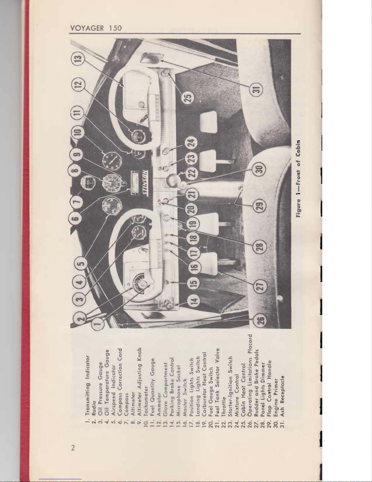
1.
Transmitting
Indicator
>
2.
Radio
C>
3.
Oil
Pressure
Gouge
QI
4.
Oil
Temperature
Gauge
5.
Airspeed
Indicdtor
VI
o
6. Compass
Correction
Card
7. Compass
8.
Altimeter
9
Altimeter
Adjusting
Knob
10
.
Tachomeler
I I. Fuel
Quantity
Gauge
12.
Ammetor
13
.
Gloy,
:
Comportment
I ".
P(II~
i
f'l9
IhCJk~
Canlrol
1,5. Mi
crophon
e Sockel
16
Ma
~
IN
Swilch
11
Po
s
ition
L
ights
Switch
18
.
Landing
Lights Switch
19.
Carburetor
Heat
Control
20
. Fuel
Gauge
Switch
21. File! Tank
Selector
Valve
22.
Throttle
23.
Slarter·lgnition
Switch
24.
Mixture
Control
25.
Cab
in Heat Conl
rol
26.
Operati
ng
Limitations
Placard
27. Rudder
and
Brake Pedals
28. Panel
lights
Dimm
er
29.
Flap
Co
rrt
rol
Handle
30.
En
g
ine
Primer
31. Ash Rece
ptacl
e
.......
---
Figure
1-
Front
of
Ca
bi
n
DESI
GN
FEA
lURES
SURFACE CONTROLS
AN
D BRAKES
6.
Th
e ailero
ns
and elevator are operated
by
dual control wheels and
shafts.
The
full up travel of the elevator
is
obtained only when the flaps
are lowered. W hen the
fl
aps are r
ai
sed, a stop
on
the el
ev
ator push-pull
tube engages tbe lower arm
of
tbe
fl
ap handle
ont
rol assembly, limit-
ing the elevator up t
1"a1)el
co
approximately nine degr
es
less than full
up travel.
7.
Th
e
fl
aps are operated by a comrol lever located between the
twO
fro
nt
seats. A three-position locking d
ev
ic
e in the control mechanism
allows the flaps
to
be
sec
in ny one of rhree positions: raised, take-off,
or landing. The
fl
aps are raised fully when the control lever
is
in the
posicion neare t
th
e BOOL
Di
sengage the locking dev
ice
by
pressing the
but
tO
n on the end of the control lever.
Do
not
fl
y at spee
ds
greater than
88
mph
with flaps down.
8.
The eleva
ro
r trim tab is operated
by
a hand crank located overhead.
Th
ere is a tab p
osiC
ion indicator on the pl
aca
rd of the crank assembly.
Th
is
control
is
prov
id
ed to correct the airplane for nose heavy or tail
heavy conditio
ns,
us
ua
ll
y caused by variations
of
loadi
ng
arrangements
or powe
r.
9.
The rudder and steerable tail wheel are controlled by both sets of
pedals.
Th
e brake
ro
e-
peda
ls
are attached
ro,
and extend abo
ve,
the left
set of
ru
dder peda
ls.
The
br
akes
ca
n be set for parking by pulling out
the parking brake control knob while the brakes are de
pr
es
se
d.
Th
e
br
akes
ca
n be used for curning the airplane while taxiing, but to avoid
exce
ss
ive brake wea
r,
the steerable tail wheel should be used
as
the
principal means of turning when
on
the ground.
FLI
GHT
INSTRUMENTS
1
0.
The altimeter, the airsp
ee
d indicato
r,
and the
co
mpa
ss
are mounted
on the instrument pane
l.
Th
e d
ia
l of the altimeter can be rotated and
set to the proper pressure altitude
by
turning the adjusting knob at the
b
ase
of the dial.
11. The airspeed indICator
is
marked with colured lines and letters
to
show the various speed range limitatio
ns
of the airplane. The green arc
ind
ic
ates the normal operating range.
Th
e white arc, inscribed along-
side the green arc mclicates (he permissib
le
speed range with the flaps
dow
n.
A
ye
llow arc mdicates the speed range at which the airp
la
ne
3
4
VOYAGER
150
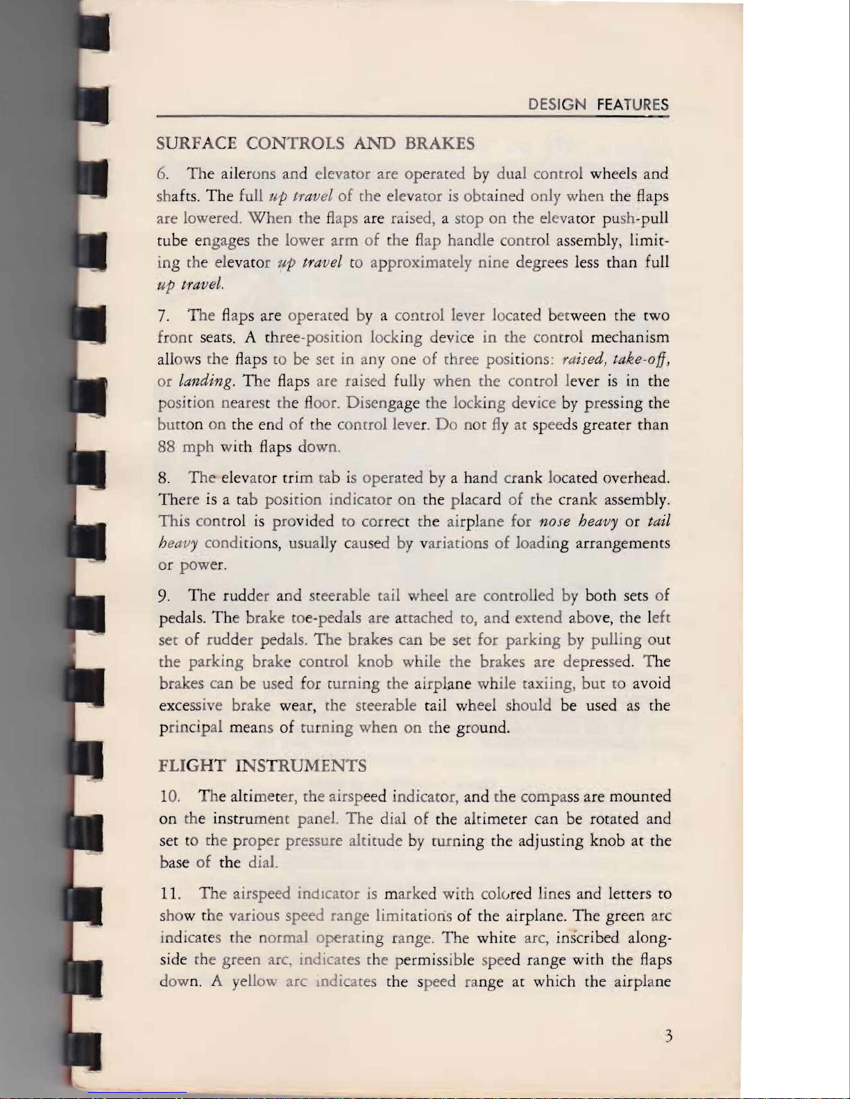
7. Ash Rece
ptacle
8.
Ba
gga
ge
li
m
itation
Placard
9.
Do
or
Ha
nd
le
10. Door
lo
ck
11.
Wind
ow
Lock
12. Air
craft
Data File
1.
Aileron
and
Fl
ap
C
ontrols
Access
Zipper
2. Dome Light Switch
J.
Radio
loud-Speaker
4. Trim
Tab
Control Access
Zipper
5. Elevator Trim Tob Control
6.
Cabin
Ventil
ator
Figure
2-Left
Side
of
Ca
bi
n
should be operated with caution
to
av
oid abru
pt
maneuvers. Red radial
lines and letters on the instrument indica
te
maximum speeds permis-
sible: "
N"
for maximum speed in the normal category (gross weight
between ]925 and 2230
pounds);
and "
U"
for maximum speed in the
utility ategory gross weight 1925 pounds or less).
12. The compass can be adjusted for eviation by turning the com-
pensatjng screws on the face of [he instrument with a non-magnetic
screw driver. T e compensating screws are located at the extreme
tOp

DESIGN
FEATURES
of the inst
rument
and are marked "N
-S
" and "E-
W"
to indicate the
ad
justment that can be made by
tu
rning the screws.
The
compass cor-
rection card is beneath the compas
s.
EN
GIN
E
CON
TROLS
AND
INDIC
AT
ORS
13. All of the power pla
nt
co
nt
rols and indicators, except the oil level
dip stick, are mounted on the control and instrume
nt
panels.
The
control
panel, beneath the main panel, exten
ds
the width of the cabin.
The
oil
level dip stick
is
on the right rear side of the engine crankcase, inside
the engine b
afHes.
14.
Th
e throttle concrol, located in the center of the control panel,
is
the push-pull
typ
e.
A
knu
rled loc
ki
ng nut adjusts the friction applied
to the push-pull rod and determines the ease with which the throttle
control can be adjusted. By turning the nut clockwise, the throttle con-
trol can
be
locked in any positio
n.
Engine speed
is
increased
by
pushing
the throttle control toward the control panel.
15.
The
fuel selector valve, mounted on the aft side of the firewall,
is
operated by a torque rod and a combination handle and pointer
on
the
control pane
l.
The
position of the valve deter
min
es from
wh
ich tank
fuel can flow to the
en
gine.
The
valve can
be
se
t to
anyone
of three
positions:
lef
t tank, right t
ank
,
or
off. W hen the valve handle
is
turned
to the off position, all fuel
is
sh
ut
off from the engine at the val
ve.
16.
The engine primer control
kn
ob
is
on the lower edge of the con-
rrol panel, below the throttle control.
To
prime the engine,
turn
the
co
nt
rol knob counter clockwise; pull the knob out
as
far
as
possible,
then push it back to the normal position.
When
the primer
is
not being
us
ed,
it
must
be
lo
cked securely
in
th
e normal position.
17.
The
combination starter and ignition switch
is
mounted on the
co
ntt
ol panel
to
the right
of
the throttle control. A stop incorporated
within th
is
swiech prevents the switch from being turned to start posi-
tion unless the button direccly above the handle
is
depressed.
The
switch
is
spring loaded and will return
to
the both magnetos position from the
start positi
on
when the switch
is
released. Both magnetos are on with
the switch in start position.
18. The carburetor heat control knob
is
mounted
on
the control panel
to the left
of
the fuel selector valve control. As the control knob is pulled
5
6
VOYAGER
150
ouc,
an increasing amount of heated air enters the carburetor.
When
the control knob
is
pu
lled all the way out, only heated air enters the
carburetor. A mixture of cold and heated air enters the carburetor when
the knob
is
set
at
intermediate points.
The
carburetor heat control can
be locked in any position to provide any desired mixture of hot and
cold air. The concrol knob m
us
t be turned to unlock the push-pull rod
before the control can be
se
t at the desired position.
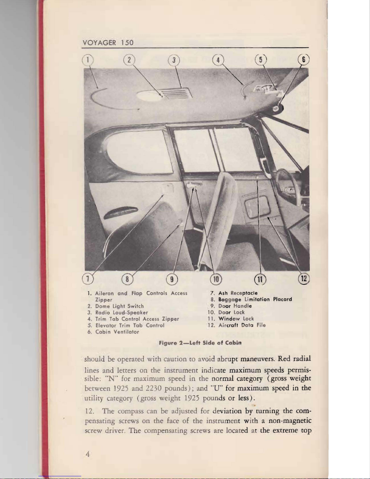
19.
Th
e primary purpo
se
of carburetor air heat
is
to eliminate or pre-
vent carburetor icing. Use carburetor heat during engine warm-up and
1.
Ri
gh
t
Po
rf Duct
2.
Cabin He
at
Control
3.
left
Ventila
t
or
4. Ri
gh
t Ve
ntilator
5.
Ve
ntilator
Air
Intake-
6.
Re
o'r
P
ort
Duct
7. Heat C
ontr
ol Valve
8. Fresh Air
Intake
9.
Heater
Muff
10. Hat
Air
Intoke
Figure
3-Heatlng
and
Ventilat
i
ng
5y
.te
m

DESIGN
FE
AT
URES
during climb whenever there
is
danger that
ice
will form in the carbu-
retor. Ice
is
most likely to form in the carbure
tOr
when the outside air
temperature
is
between 20 and 68 degrees Fahrenheit. Use heat also
during any prolonged glide or descent. Any time the engine loses speed
without apparent cause, the use of carburetor heat may correct the con-
dition.
Do
not use carburetor heat during take-off or landing.
20. The mixture control knob, mounted on the control panel to the
right of the ignition-starrer switc
h,
regulates the amount of fuel in the
fuel-air mixture going into the engine.
With
the control pushed in, the
mixture
is
full rich. Pulli
ng
the knob out leans the mixture progres-
sively until, at full extension of the control, the idle cut-off stops the flow
of fuel at the carburetor.
21.
When
flying at altitudes greater than 3000 feet above sea level,
use mixture control to lean carburetor fuel-air mixture to obtain smooth
engine performance. Stop engine by use of idle cut-off on mixture
control.
22. The t
ac
hometer, oil pressure gauge, and oil temperature gauge are
mounted on the instrument pan
el.
An
ind
ic
ator that registers accumu-
lated hours
of
engine operation, recordi
ng
one ho
ur
at 2566 rpm,
is
an
integral part
of
th
e tachometer.
23. The oil pressure gauge
is
mounted to the rig
ht
of
the left control
wheel.
Th
e sa
fe
operating pressure range for the engine is marked on
this instrument by a green arc with red radial lines at its extremities,
35
psi mini
mum
and 55 p
si
maximum.
Do
not operate the engine at
full throttle when the oil pressure
is
outside of these limits.
24. The oil temperature gauge is mounted to the right of the oil pres-
sure gauge.
The
normal operating temperature range for the engine
is
marked
on
this instrument by a green arc.
The
yellow arc indicates the
temperature at which the engine m
ay
be operated with caution, and a
red radial line indicates the extreme high temperature of 230 degrees
Fahrenheit that must never
be
exceeded. The caution range
is
from 60
to 80 degrees Fa
ru
enheit.
HEAT
IN
G
AND
VENTILAT
ING
25.
Th
e cabin heat concrol knob regulates the temperature of the air
ent
ering the cabin through three heater
po
r
ts.
W ith the control pushed
7
VOYAGER
150
R
7
II
10
16
'ST
36
L.H.
TANK
TRANS
~
19
N
LANDING
LIG
HTS
G
5
15
FU
EL
GAUGE
BATTERY
§
12Y
RELAY
-
{-
FU
EL
R
l~:
N~
T
RA
NS.
-=
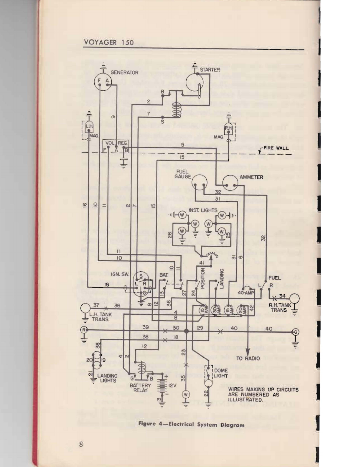
Figure
4-Electrlcal
System
D
iagram
8
DESIGN
FEATURES
in, unheated air enters throLlgh the ports and when the control
is
pulled
out, heated air
is
supplied.
The
temperature of the incoming air
is
regu-
lated according to the amount the knob
is
pulled out. Outlets for the
front seats are located on the firewall under the instrument panel
on
each
side of the cabin. A grilled outlet, located in the cabin floor just behind
the front seats,
is
provided for the rear of the cabin. These outlets may
be individually lased to modify the distribution
of
air
as
desired.
26. Additional ventilation
is
provided by two ports admitting fresh
air; one at each
up
per c rner of the windshield. These vents are opened
by pulling
out
the cylindrical tubes.
The
tube may be rotated to direct
a stream of fresh air in any desired direction.
E
LE
CT
RIC
AL
SY
ST
EM
27. A 12-volt battery and engine-driven generator, supply power for
the single wire type electrical system (refer to Figure
2).
The
battery
and its case are mounted under the left front seat.
The
case
is
vented
and provided with a drain to prevent acid damage to the airplane
or
inj
ur
y to its occupants. The battery supplies the power to start the en-
gine.
The
generator suppli
es
energy to the electrical system after the
engine
is
operating at sufficient speed. Electrical power from the gen-
erator
is
fed into the electrical system through a voltage regulator that
maintains constant voltage
in
the system. Power from b
ot
h the battery
an
d the generator is supplied
to
a main bus from which current
is
drawn for the various electrical circuits.
28. The master switch co
nt
rol
is
a combination battery relay switch
and generator field switch and must be
on
before current
is
supplied to
the electrical system. W hen the master control switch
is
on) the battery
relay closes and allows the
ba
tt
ery
to
supply current to the main bus;
it also completes the generator
fiel
d circuit that allows the generator
to
develop voltage. T
he
airplane may be operated in flight with the master
control switch off)
but
the generator will not charge, nor will any elec-
trical equi
pm
em opera
te.
29.
The
electrical system is divided i
nt
o the following five main cir-
cuits: eng
in
e starting, na igarion lights, panel lights, dome light, landing
lights,
fu
el ta
nk
level gauge, and radio.
The
main bus, from which
power for the vanous
Clf
CUHS
is
taken,
is
mounted
on
the forward side
of
the co
nt
rol panel. under the radio. Curre
nt
for the circuits, except
9
12
J
)
1
VOYA
GE
R
150
are a transmitter-receiver unit, a loudspeaker, and a
microphon~.
Two
jac
ks
are provided, one for the microphone and the other for head-
phone
s.
Headphones are not normally required because of the loud-
speaker installation.
j6
. The airplane
is
equipped with two antennas, an extern!ll
~ntenn~
that extends from the top of the tabin to the verdcal stabilizer, apd a
fixed
loop antenna inside the fuselage, aft of the cabin
(ref~r
to
Fig~
ure 5).
Th
e loop
is
perpen<1icular
to· the longitudinal axis of the
air,.
plape
so
that homing
is
accomplished
by
tuning the null.
37.
Transmission
may
be
accomplished at any setting of the radio
contro
ls
as long
as
the radio
is
operating. The transmitter
is
activated
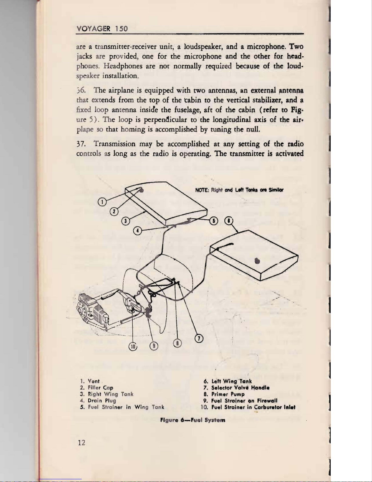
NOTE:
R
iO
ht
and
UIt
Tonka
en
SImIlar
1.
Vent
6.
Le'ft
Wing
'Tank
2. F
ill
er Cap 7.
Selector
Vaivi
l1andl.
3. R
ig
ht Wing Tank 8. Primer Pump
4.
Dr
ain
Pl
ug 9. Fuel
Strainer
On
Firewall
5. Fuel
Stra
i
ner
in
Wing Tan k 10. Fuel
Strainer
in C
arbur.tor
1"I.t
Fi
gu
re
6-F
u
el
Sys
te
m
J
DES
IGN F
EAT
URES
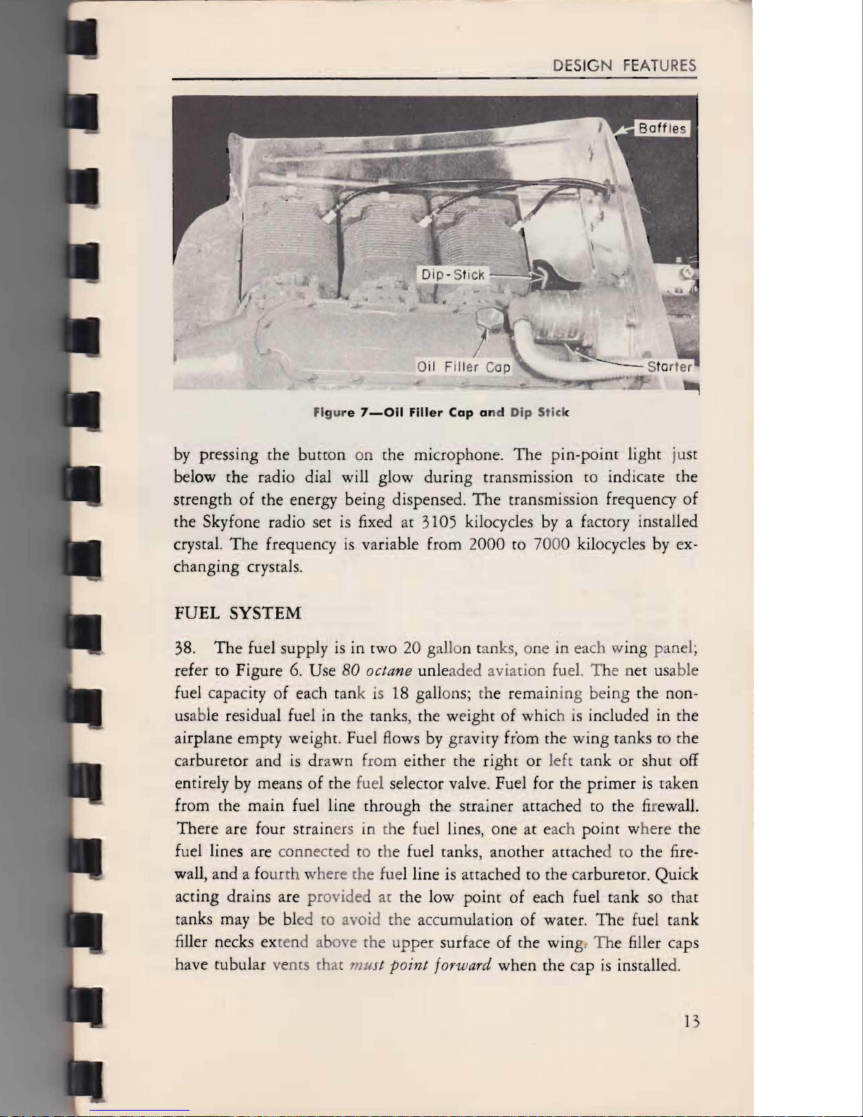
Fi
gur
e
7-0il
Filler
Cap
an
d
Dip
Stick
by
pressing the
button
on
the microphone.
The
pin-point
light just
below the radio dial will glow
during
transmission to indicate the
strength
of
the energy being dispensed.
The
transmission frequency
of
the Skyfone radio set
is
fixed at 3105 kilocycles by a factory installed
crystal.
The
frequency
is
variable from 2000 to 7000 kilocycles by ex-
changing crystals.
FUEL
SYSTEM
38.
The
fuel supply
is
in two 20 gallon tanks, one in each wing
pa
nel;
refer to Figure
6.
Use
80
octa
ne
unleaded aviation fuel. The net usable
fuel capacity of each tank
is
18 gallon
s;
the
rem
aining being the non-
us
able residual fuel in the tanks, the weight
of
which is included in the
airplane empty weight. Fuel Bows by gravity fr'om the
wing
tanks to the
carburetor and
is
drawn from either the
right
or left tank or shut off
entirely by means
of
the fuel selector valve. Fuel for the
primer
is
taken
from the
main
fuel line through the strainer attached to the
fi
rewall.
There are four strainers
in
the fu
el
lines, one at each
point
where the
fuel lines are connected to the fuel tanks, anOther attached
to
the fire-
wall, and a fo
urth
where the fuel line is attached to the carburetor. Quick
acting drains are provided
at
the low
point
of each fuel tank so that
tanks may be bled
ro
avoid the accumulation
of
water.
The
fuel tank
filler necks extend above the
upper
surface of the wing:
Th
e filler caps
have tubular vents that
mu
st p
oint
fo
rw
ard when the cap is installe
d.
13
VOYAGER
150
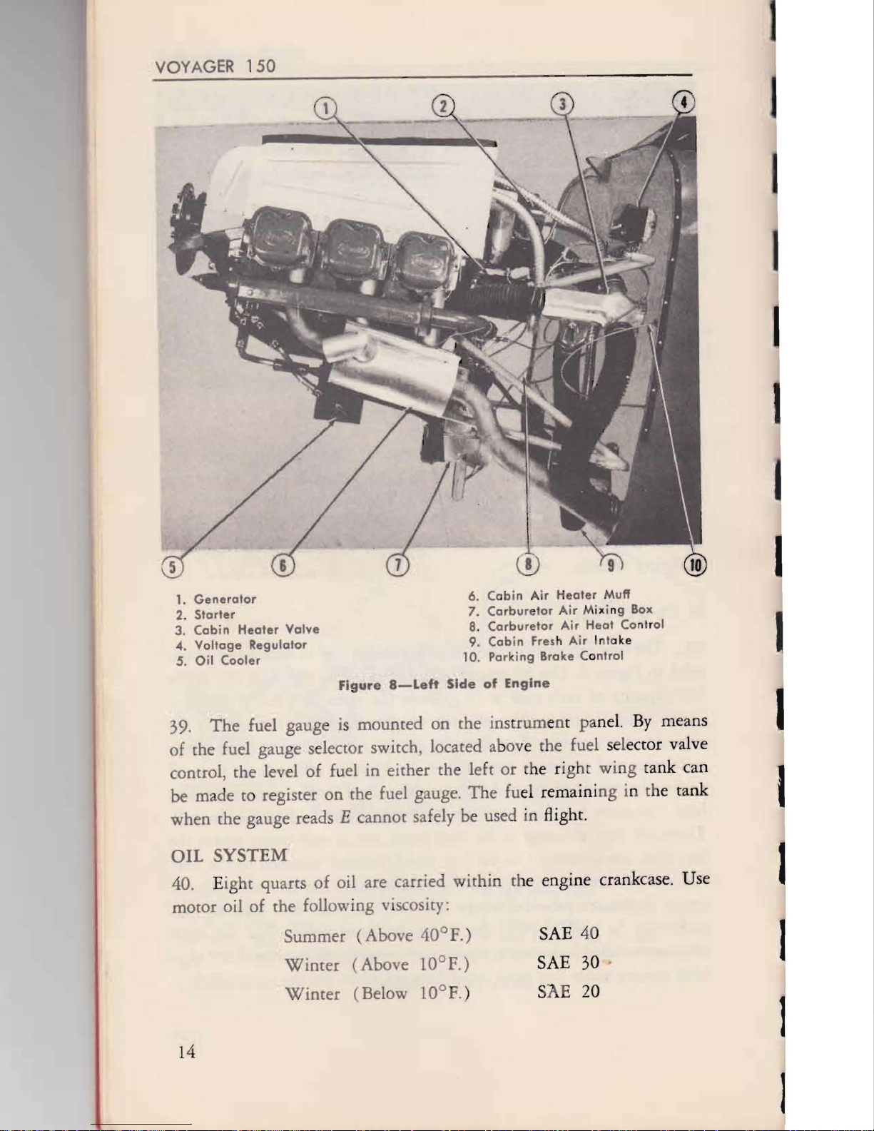
1.
Generator
2.
Starter
3.
Cabin
Heater
Valve
4.
Voltage
Regulator
S.
Oil
Cooler
39.
The
fuel gauge
is
mounted
on
the
instrum
e
nt
panel.
By
means
of
the fuel
gauge
selector switch, located above the fuel selector valve
control, the level
of
fuel
in
either the left
or
the ri
gh
t
wing
t
ank
can
be
made to register
on
the fuel gauge.
The
fu
el
remaini
ng
in the
tank
when
the gauge reads E
cannot
safely be used in flight.
OIL
SYSTEM
40. Eight quarts
of
oil are carried
within
the engine crankcase. Use
motor
oil
of
the
following viscosity:
Summer
(Abo
e
40°F.)
SAE 40
Wincer
(Above
lOoF.)
SAE 30
Winter
(Below
lOoF.) ShE
20
14
6.
Cabin
A
ir
Healer
Muff
7.
Carbur
e
tor
Air
Mixing Box
8.
Carburetor
Air
Heat Conlr
ol
9.
Cabin
Fres
h
Air
In
to
ke
10. Parking Broke Control
Figure
8-Left
Side
of
Engine

DESIGN
FEATURES
1.
C
abin
He
ater
Duct 7.
Mixture
Co
ntro
l
2.
Gen
er
a
to
r 8. C
ar
bu
re
to
r
3.
Ri
ght M
agn
eto
9. Thro
ttle
Con
tro
l
-t.
Starter
10. Primer Line
5. Engine Shock M
ount
11.
Carburet
or
Air
Heater
Muff
6. Fuel
St
r
ain
er
Fi
gur
e
9-Rlght
S
id
e
of
Engine
A dip-sti k for measuring the quantity of oil in the engine
is
acces-
sible upon lifting the right engine cowl panel. The stick
is
on the top
right side of the engine crankcase, inside the baffles. Never operate the
engine with less than 4 quarts of oil in the crankcase. Oil pressure and
temperature gauges are mounted on the instrument panel (see para-
gr
aphs
23
and
24).
EN
GI
NE
A
ND
ENGINE
AC
CES
SORIES
41. The power plant
is
an ai
r-
co
le
d,
six-cylinder, horizontally op-
posed
15
0 ho
rs
epower Franklin engine.
Th
e rated maximum contin-
uous engine s
pe
ed
is
2600 pounds rpm. The propeller '
is
mounted
directly on the crankshaft.
15

16
VOYAGER
150
Lock Release
I
I
I
I
Figure
10-
Sea'
L.ock
Relea$e
42. The engine accessories include a starter, a generator, two mag-
netos, a carburetor, a carburetor air filter, an oil cooler, and a carburetor
heater muff. Refer to Figures 8 and
9.
The starter
is
mounted on the
top aft end of the engine crankcase. The magnetos are below and on
each side of the starter, and the generator
is
directly below the starter
and magnetos. The carburetor
is
attached to the lower aft end of the
engine. The oil cooler and carburetor air
fi
lter are mounted
ben~ath
the forward end of the engine. The carburetor heater muff
is
attached
to
the right exhaust manifold and the muff for cabin heat
is
on the left
exhaust manifold.
ACCOMMODATIONS
43. Seats are provided for four persons. The from seats are adjustable
and can
be
moved forward or back
by
releasing a locking device (see
Figure
10).
The backs of both front seats fold forward permitting en-
trance to the rear seats.
44. The rear
se
ats are the hammock type and are not adjustable. Three
straps support
ea
ch of the rear sea
ts,
and either or both seats can
be
removed easily. Each seat
is
provided with a safety belt. Inasmuch
as
the lower cushions are not
sec
ured, it
is
recommended that the safety
belts be strapped across the rear seat cushions when these seats are
not occupied.
DESIGN
FEATURES
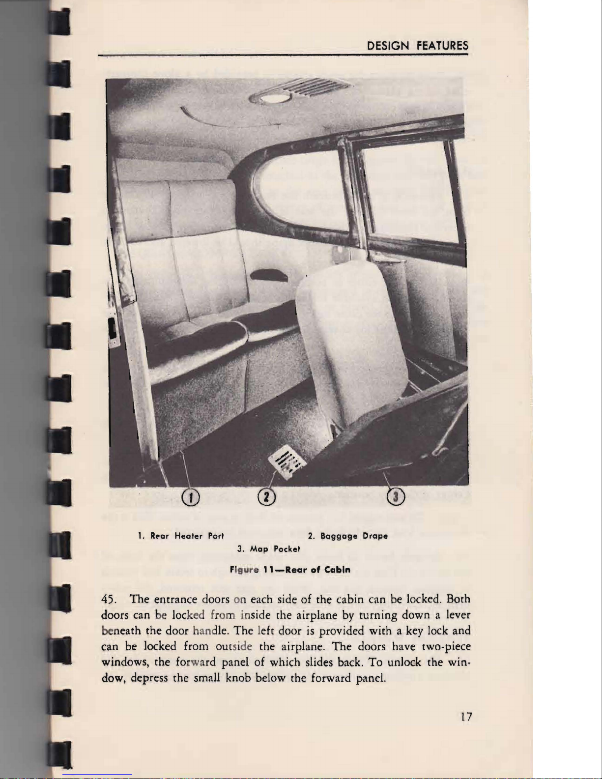
1.
Rpar
Heater
Port
2.
Baggage
Drape
3.
Map
Pocket
F
igur
e
ll-Rear
of
Cabin
45.
The
entrance doors on each side
of
the cabin can be locked. Both
doors can be locked from inside the airplane
by
turning
down a lever
beneath the door hand
le.
The left door
is
provided with a key lock and
can be locked from outside the airplane.
The
doors have two-piece
windows, the forward panel of which slides back.
To
unlock the win-
dow, depress the small knob below the forward panel.
17

VOYAGER
150
46. Stowage space for small articles
is
provided by a glove comP
tt
Ft-I
ment
on
the instrument panel, and by
twO
pockets in the upholstery.
One
pocket
is
on the back of the right front seat and another
is
on
the
left side of the cabin just forward of the cabin door. There are ash
receivers
at
the side of each seat.
BAGGAGE
47. Provi
si
on
is
made beneath the rear seat for baggage.
The
drape
from the fro
nt
edge of the seat
is
attached to the floor
by
curtain
fasteners. Unsnapping these fasteners will allow access to this space.
After the baggage
is
in place, the drape should be lowered and securely
fastened to the floor.
48. Removal of either or both sections of the rear seat will make the
rear of the cabin available for larger baggage
or
light cargo.
Th
e)
()r-
ward tube across the
ca
bin may also. be removed.
To
remove either seat
section, lift off the lower seat cushion and unlock the canvas hammqfk
straps.
49. Any combination of baggage, passengers, and
fuel
may be
carr
~
~d
that does not exceed
anyone
of the following limitations.
The
rear seat I
cannot be occupied during the performance
of
maneuvers.
(a)
Do
not exceed 2230 pounds gross weight.
See
Actual
Weight
and Balance sheets for airplane weight empty. . I
(b)
.
Do
not exceed most rearward Center of Gravity posit
ien
.per-
missible. See Operating Limitations Manual for effect of baggage
on
Center of Gravity position.
(c)
Do
not exceed 350 pounds on floor in rear of cabin. This
is
the
maximum load for which the floor structure
is
approved. I
50
. Securely fasten all loads.
The
drape extending from the front
of
the seat to the floor has been proven strong enough to retain 100 pounds
of baggage beneath the seat.
Wi
th the rear seat removed, the safety
belts and their lugs on the floor may be used to secure baggage
or
cargo. I
STATIO
N W A
GON
51.
The
Station
Wagon
loading limitations are the ,same
as
for the I
standard airplane
as
given in paragraph 49, except for the rear
of
the I
18
DESIGN
FEATURES
cabin. Baggage
is
not to be carried beneath the rear seats at any time.
A maximum load of 90 pounds per square foot, not to exceed a total
of 600 pounds,
is
permissible on the floor with the rear seats removed.
52. A sling is provided to secure cargo loads against forward motion.
The straps on each side are attached to the rear outer seat belt lugs, and
the center strap
is
attached to the rear
ce
nter seat belt lug. Position
sling over the
up
per forward corner of the cargo and draw all buckles
tight. Keep load a minimum of eight inches aft of front seat back.
BAGGAGE COMPARTMENT
53. A separate baggage compartment aft of the cabin
is
provided
1ll
later airplanes. This compartment
is
designed to carry 100 pounds and
has a capacity of
13
cubic feet. Baggage placed in this compartment
need not be tied down. This compartment
is
accessible through a door
in the right side of the fuselage, aft of the cabin. This door
is
provided
with a key lock.
19
This manual suits for next models
1


