AEROCET 5850 User manual
ISSUE
DATE:
10/17/06
Incorporated
PAGE
1 of 81
TITLE:
ICA Maintenance Manual for
FILE NO.
A-10034
REVISION
DATE:
9/10/12
SUBTITLE:
5850 Floats on a
DHC
-
2, Beaver
REVISION
2
MAINTENANCE MANUAL AND INSTRUCTIONS FOR CONTINUED
AIRWORTHINESS
FOR
AEROCET MODEL 5850 TWIN SEAPLANE FLOATS
INSTALLED ON A DEHAVILLAND DHC-2 BEAVER AIRPLANE
Aerocet, Inc.
P.O. Box 2119
265 Shannon Lane
Priest River, Idaho 83856
Phone: (208) 448-0400
Fax: (208) 448-1644
This ICA must be followed when Aerocet 5850 Floats are installed in
accordance with Supplemental Type Certificate (STC) No. SA01722SE .
The information contained in this document supplements or supercedes the basic
manuals only in those areas listed herein. For limitations, procedures, and
performance information not contained in this manual, consult the basic aircraft
ICA or maintenance manual.
ISSUE
DATE:
10/17/06
Incorporated
PAGE
2 of 81
TITLE:
ICA Maintenance Manual for
FILE NO.
A-10034
REVISION
DATE:
9/10/12
SUBTITLE:
5850 Floats on a
DHC
-
2, Beaver
REVISION
2
This page intentionally left blank
ISSUE
DATE:
10/17/06
Incorporated
PAGE
3 of 81
TITLE:
ICA Maintenance Manual for
FILE NO.
A-10034
REVISION
DATE:
9/10/12
SUBTITLE:
5850 Floats on a
DHC
-
2, Beaver
REVISION
2
LOG OF REVISIONS
Revision Pages Affected Description Date Approved
0 All Initial Release 10/17/2006
1 34 Corrected Bullets to BOM Items 2/27/07 T. Hamilton
37 Corrected column headings in BOM
47, 48, 49 Revisions to 56-15230, 56-15240 &
56-15260 – changed bolts to pins.
56, 57 Revisions to 56-10114 – fiberglass wear
strips.
63 Revisions to 56-10180 – fiberglass wear
strips.
64 Revisions to 56-10400 – access panel
fasteners changed to truss head.
2 All Entire Re-release.
Where Notes or Cautions are given,
formatted the verbiage for better
emphasis – not marked with change bar.
Where applicable, breaks were
introduced to start new sections on odd
pages.
Adding new sections unavoidably pushes
the subsequent outline numbers in
Section 2 upward sequentially.
1/23/12
7 Added Figure 1.1.1
8 Added Figure 1.1.2
9 Added Figure 1.1.3, 1.1.4 & 1.1.5
10-11 Added paragraph explaining
Airworthiness Limitations.
12 Added Section 1.3 Availability
13-17 Added Section 2.2 and figures for
Fastener Torque, and Use and Discretion
19 Corrected Figure reference
21 Corrected two figure references.
Changed UHMW wear strips to
fiberglass.
22 Corrected Figure reference
ISSUE
DATE:
10/17/06
Incorporated
PAGE
4 of 81
TITLE:
ICA Maintenance Manual for
FILE NO.
A-10034
REVISION
DATE:
9/10/12
SUBTITLE:
5850 Floats on a
DHC
-
2, Beaver
REVISION
2
Revision Pages Affected Description Date Approved
22 Added Figure 2.6.1.
Added description of new fwd hinging
locker panels.
23 Added Figure 2.6.2 showing fwd hinging
latch operation.
24 Added Figure 2.6.3
30 Corrected Figure Reference.
33 Added Troubleshooting Section 2.10.
37 Corrected “(above)” to “(below)”
38 Added Hydrex 33350 and show old resin
as 33253 obs.
40 Changed UHMW wear strips to
fiberglass.
“Affix strips as shown in diagram
below.” changed to “Affix strips as
shown in diagram.”
41 Added Airworthiness Limitations Section
4. (Following section numbers
sequentially bumped)
65 Added missing balloons.
66 Changed 56-15280 to 56-15285.
69 Replaced figure showing new 56-15145-
02
72 Updated Locker to show only fiberglass
style wear strips. Inboard version now
identified with “-1”.
73 Added FWD hinging “-2” Locker inst.
75 Corrected cable guide orientation.
76 Lwr. Tiller bracket attch. Bolts
lengthened from -7A to -10A.
77 Now showing placard.
79 Now showing machine screws, hrdwr.
Originally prepared by Fliegen Works Inc., Portland, OR

ISSUE
DATE:
10/17/06
Incorporated
PAGE
5 of 81
TITLE:
ICA Maintenance Manual for
FILE NO.
A-10034
REVISION
DATE:
9/10/12
SUBTITLE:
5850 Floats on a
DHC
-
2, Beaver
REVISION
2
Table of Contents
Log of Revisions .....................................................................................................3
1.
Introduction............................................................................................................7
1.1.
General Description..........................................................................................7
1.2.
How to Use This Supplemental Manual........................................................10
1.3.
Availability: .....................................................................................................12
2.
Maintenance Manual...........................................................................................13
2.1.
Lubrication ......................................................................................................13
2.2.
Fastener Torque..............................................................................................13
2.3.
Fastener Torque Values (Except where otherwise noted)...........................15
2.4.
Fastener Use and Discretion...........................................................................17
2.5.
Float Handling and Jacking...........................................................................17
2.6.
Floats Installation............................................................................................18
2.7.
Conversion from Wheels to Floats.................................................................25
2.8.
Conversion from Floats to Wheels.................................................................31
2.9.
Testing Floats...................................................................................................32
2.10.
Troubleshooting ..............................................................................................33
3.
Repair Manual, PSM 1-2-3 .................................................................................35
3.1.
Struts ................................................................................................................35
3.2.
Composite Float Hulls ....................................................................................35
3.3.
Repair Types and Procedures........................................................................36
3.4.
Impregnation of Fabric ..................................................................................37
3.5.
Resin Mixing....................................................................................................38
3.6.
Preparation of Fiberglass Materials..............................................................38
3.7.
Surface Coat Application (Gel Coat) ............................................................39
3.8.
Keel and Wear Strip Bonding........................................................................39
4.
Airworthiness Limitations ..................................................................................41
4.1.
GENERAL.......................................................................................................41
4.2.
DESCRIPTION...............................................................................................41
5.
Instructions for Continued Airworthiness.........................................................43
5.1.
General Practices ............................................................................................43
5.2.
Product Listings ..............................................................................................43
5.3.
Part 1, Preflight...............................................................................................44
5.4.
Part 2, Daily Inspections.................................................................................44
5.5.
Part 3, Periodic Inspections............................................................................44
5.6.
Special Inspections..........................................................................................46
6.
Illustrated Parts Catalogue.................................................................................47
6.1.
List of Figures..................................................................................................47

ISSUE
DATE:
10/17/06
Incorporated
PAGE
6 of 81
TITLE:
ICA Maintenance Manual for
FILE NO.
A-10034
REVISION
DATE:
9/10/12
SUBTITLE:
5850 Floats on a
DHC
-
2, Beaver
REVISION
2
This page intentionally left blank.
ISSUE
DATE:
10/17/06
Incorporated
PAGE
7 of 81
TITLE:
ICA Maintenance Manual for
FILE NO.
A-10034
REVISION
DATE:
9/10/12
SUBTITLE:
5850 Floats on a
DHC
-
2, Beaver
REVISION
2
1. INTRODUCTION
Thank you for choosing Aerocet Floats. This manual covers the installation and
maintenance of the 5850 floats as installed on the DHC-2 Beaver airplane, including
instructions for installing the struts, steps, water rigging, and float structure. An IPC is
also provided.
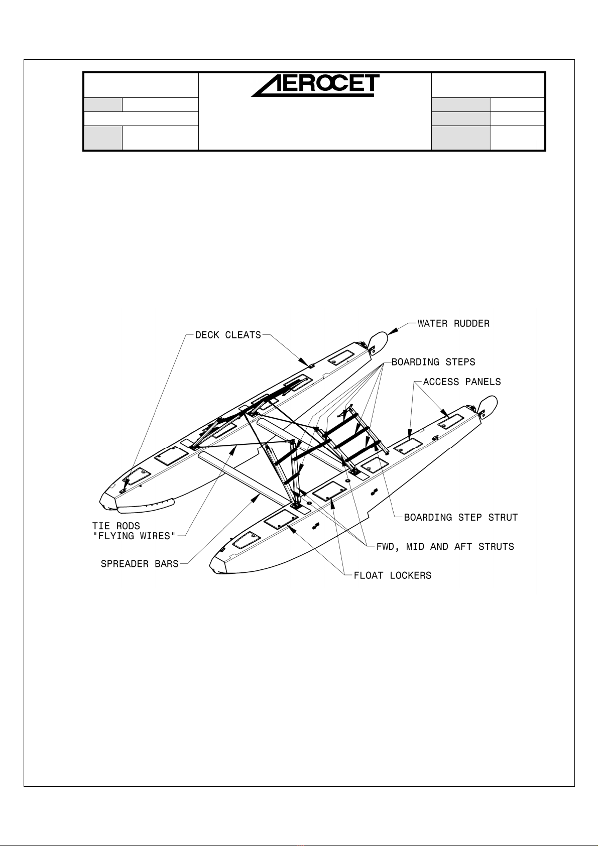
1.1. General Description
Figure 1.1.1. Showing Overview of Basic Components
The Aerocet Model 5850 Twin Seaplane Floats are all-composite float hulls. The
float hulls are separated by spreader bars that slide into the float assemblies. The float
design uses a double-fluted bottom contour from the step forward, and has a flat top deck
design with built-in antiskid. Each float offers two large storage lockers.
ISSUE
DATE:
10/17/06
Incorporated
PAGE
8 of 81
TITLE:
ICA Maintenance Manual for
FILE NO.
A-10034
REVISION
DATE:
9/10/12
SUBTITLE:
5850 Floats on a
DHC
-
2, Beaver
REVISION
2
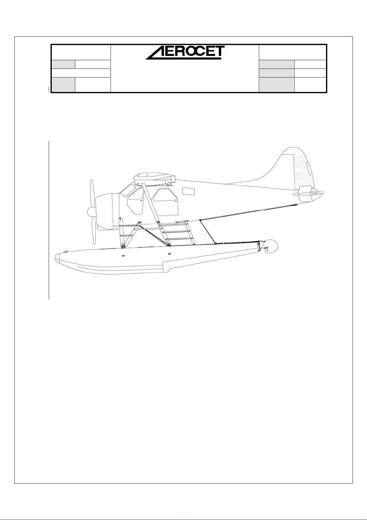
Water rudders are mounted on the stern of each float for water-taxi operations, and
are connected directly to the airplane’s rudder. The retract system, which is compatible
with OEM and other approved cockpit handles, is installed in the standard manner.
Figure 1.1.2 Side View of Model 5850 Floats on a DeHavilland DHC-2 "Beaver"
Each float is attached to the airplane by forward, mid, and aft struts. An attachment
block is bolted to the upper end of the forward strut. The upper end of the mid and aft
struts each have a forked attachment fitting bolted to them, and each of these forked
attachments is bolted to a landing gear attachment lug on the side of the fuselage. At the
lower end, the forward and mid struts are bolted to a common forked attachment fitting
that is also bolted to the forward attachment lug on the float. The aft strut forked
attachment fitting is bolted independently to the rear lug on the float.

ISSUE
DATE:
10/17/06
Incorporated
PAGE
9 of 81
TITLE:
ICA Maintenance Manual for
FILE NO.
A-10034
REVISION
DATE:
9/10/12
SUBTITLE:
5850 Floats on a
DHC
-
2, Beaver
REVISION
2
Figure 1.1.3 General Float Terms
Figure 1.1.4 Front View of Floats and Rigging
Figure 1.1.5 Model 5850 Float, Side View
ISSUE
DATE:
10/17/06
Incorporated
PAGE
10 of 81
TITLE:
ICA Maintenance Manual for
FILE NO.
A-10034
REVISION
DATE:
9/10/12
SUBTITLE:
5850 Floats on a
DHC
-
2, Beaver
REVISION
2
1.2. How to Use This Supplemental Manual
Used in conjunction with the DeHavilland Maintenance Manual, Repair Manual,
and Illustrated Parts Catalogue for a DHC-2, Beaver, airplane, this supplemental manual
provides the operator with a source of information for installing, removing, repairing, and
maintaining Aerocet Model 5850 Twin Seaplane Floats on a DHC-2 Beaver. Instructions
in this supplemental manual replace specific, noted sections of the DeHavilland manual.
This manual is organized as follows:
Maintenance Manual. Instructions and information necessary to maintain, install,
and remove the Aerocet Model 5850 Twin Seaplane Floats on a DeHavilland DHC-2
Beaver airplane. This dovetails into existing sections of the DeHavilland Maintenance
Manual, PSM 1-2-2.
Repair Manual. Instructions necessary to repair Aerocet Model 5850 Twin
Seaplane Floats installed on a DeHavilland DHC-2 Beaver airplane. These instructions
replace sections 5.8 through 5.15 of Section V, Alighting Gear in the DeHavilland Repair
Manual, PSM 1-2-3.
Instructions for Continued Airworthiness. Instructions necessary to inspect and
maintain an airworthy state with Aerocet Model 5850 Twin Seaplane Floats on a
DeHavilland DHC-2 Beaver airplane. These instructions include Preflight, Daily,
Periodic, and Special inspections. This information dovetails into existing sections of the
DeHavilland Maintenance Manual, PSM 1-2-2.
Illustrated Parts Catalog. Drawings and parts necessary to use the Aerocet Model
5850 Twin Seaplane Floats on a DeHavilland DHC-2 Beaver airplane. This section
should be used in lieu of the float sections in the DeHavilland Illustrated Parts Catalogue,
PSM 1-2-4.
Airworthiness Limitations Section. The Airworthiness Limitations Section is
required per 14 CFR 23.1529. This includes mandatory replacement times for type

ISSUE
DATE:
10/17/06
Incorporated
PAGE
11 of 81
TITLE:
ICA Maintenance Manual for
FILE NO.
A-10034
REVISION
DATE:
9/10/12
SUBTITLE:
5850 Floats on a
DHC
-
2, Beaver
REVISION
2
certification, mandatory inspection times for type certification and inspection procedures
for those approved mandatory times.

ISSUE
DATE:
10/17/06
Incorporated
PAGE
12 of 81
TITLE:
ICA Maintenance Manual for
FILE NO.
A-10034
REVISION
DATE:
9/10/12
SUBTITLE:
5850 Floats on a
DHC
-
2, Beaver
REVISION
2
1.3. Availability:
One complete copy of this manual shall be provided with each new set of Aerocet
Model 5850 floats. Additional copies and minor revisions shall be available via email,
U.S.P.S (Mail), UPS or FedEx by request. Fees and delivery charges may apply.
Notification of any changes that require service for airworthiness shall be
distributed to all applicable Aerocet owners on record with Aerocet, Inc. In such a case,
copies of the applicable, revised portions of this manual shall be provided.
Aerocet, Inc. maintains record of purchasers and/or owners collected at the time of
purchase in order to comply with the above as well as to maintain a high standard of
service. If you have moved since your original purchase, have purchased a used product
or otherwise have reason to believe that the contact information on file is incorrect,
please provide the following information to Aerocet, Inc: (Aerocet contact information is
on the front of this document.)
Float Information:
Float Model: _________________________________
Float S/N (R/L) _______________________________
Aircraft Information:
Aircraft Make/Model __________________________
Aircraft Registration ___________________________
Aircraft S/N _________________________________
Owner Information: (as applicable)
Previous Owner ______________________________
Previous Address _____________________________
Present Owner _______________________________
Present Address ______________________________
Present Phone Number ________________________
Present Email Address _________________________

ISSUE
DATE:
10/17/06
Incorporated
PAGE
13 of 81
TITLE:
ICA Maintenance Manual for
FILE NO.
A-10034
REVISION
DATE:
9/10/12
SUBTITLE:
5850 Floats on a
DHC
-
2, Beaver
REVISION
2
2. MAINTENANCE MANUAL
2.1. Lubrication
Replaces paragraph 1.29 of the DeHavilland Maintenance Manual, PSM 1-2-2.
None required. Corrosion protection covered in the Instructions for Continued
Airworthiness (ICA).
2.2. Fastener Torque
2.2.1. Torque Value Conversion:
To convert in.-lbs. to ft.-lbs: Value (ft.-lbs.) x 12 = Value (in-lbs.)
To convert ft.-lbs. to in.-lbs: Value (in-lbs.) x 0.0833 = Value (ft.-lbs.)
2.2.2. Tooling Requirements:
Calibrated torque wrench
Adapters that affect the length of the torque wrench will affect the required
torque indication and must be calculated according to Figure 1.4.3.
2.2.3. Hardware Cleanliness
All hardware is to be free of dirt, grit and grease. All dirty hardware shall be
thoroughly cleaned and lubricated with a dry film lubricant such as LPS 1, or
Teflon products per manufacturer instructions. It is recommended that all
stainless hardware be thoroughly lubricated with anti-seize lubricant of good
quality to prevent galling upon assembly.
2.2.4. Torque Procedure
Assure that hardware is clean and properly prepared for installation. Assemble
nuts to bolts, measuring the tension required to turn the nut and add this to the
required final torque. Where possible apply torque to the nut, and not to the
fastener head. Apply a smooth, even pressure, stopping and re-torquing if
chattering or premature loading occurs. This may warrant disassembly and
subsequent inspection for burrs or galling. Replace any damaged hardware.

ISSUE
DATE:
10/17/06
Incorporated
PAGE
14 of 81
TITLE:
ICA Maintenance Manual for
FILE NO.
A-10034
REVISION
DATE:
9/10/12
SUBTITLE:
5850 Floats on a
DHC
-
2, Beaver
REVISION
2
Access panels should be torqued only to "hand tight", the fiberglass should
exhibit only mild deformation. A portable hand drill could be used, provided
that the clutch is set properly. Do not apply more pressure to the hatch screws
than is necessary to engage the tool to the fastener head as this will risk
damaging the Tinnerman style nuts below.
All other nuts shall be torqued per Section 2.3 unless otherwise noted.
ISSUE
DATE:
10/17/06
Incorporated
PAGE
15 of 81
TITLE:
ICA Maintenance Manual for
FILE NO.
A-10034
REVISION
DATE:
9/10/12
SUBTITLE:
5850 Floats on a
DHC
-
2, Beaver
REVISION
2
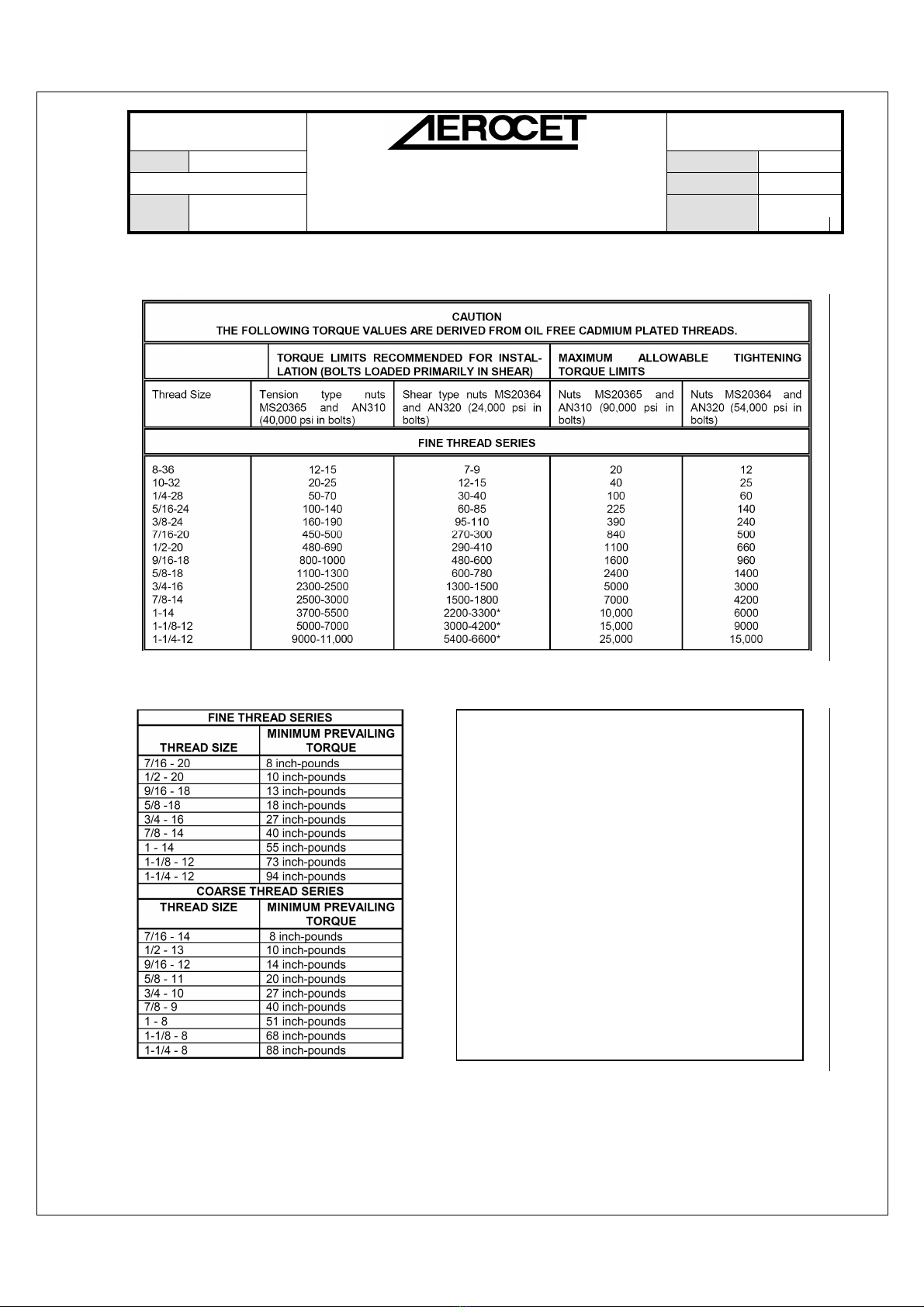
2.3. Fastener Torque Values (Except where otherwise noted)
Figure 2.3.1 Recommended Torque Values (inch-pounds)
(from AC43.13-1B, Table 7-1)
Figure 2.3.2 Minimum Prevailing Torque Values for Re-used Self-Locking Nuts
(from AC43.13-1B, Table 7-2)
Self-Locking Nuts:
Self-locking nuts, when re-used, must
have at least the minimum prevailing
torque listed in figure to the left. Nuts that
are smaller than those listed in the table
shall not be used if they can be run up by
hand.

ISSUE
DATE:
10/17/06
Incorporated
PAGE
16 of 81
TITLE:
ICA Maintenance Manual for
FILE NO.
A-10034
REVISION
DATE:
9/10/12
SUBTITLE:
5850 Floats on a
DHC
-
2, Beaver
REVISION
2
Figure 2.3.3 Torque Wrench with Various Adapters
(from AC43.13-1B, Figure 7-2)

ISSUE
DATE:
10/17/06
Incorporated
PAGE
17 of 81
TITLE:
ICA Maintenance Manual for
FILE NO.
A-10034
REVISION
DATE:
9/10/12
SUBTITLE:
5850 Floats on a
DHC
-
2, Beaver
REVISION
2
2.4. Fastener Use and Discretion
2.4.1. Fastener Lengths
Rivets: Where replacement or repair of rivets is required, use rivets of proper
specifications only. For instance, MS203426AD4-xxx. Lengths may be
determined by measuring the thickness of the material(s) to be assembled and
adding 1.5" X Diameter of the rivet to be used. Over-sized rivets may be
substituted where holes have been drilled out.
Bolts and screws shall have a minimum of one thread visible through the nuts upon
final torque.
Washers may be rearranged if necessary to accommodate proper fit, up to two
washers beneath the nut and one beneath the fastener head. Typically, Aerocet
intends to put one thin washer beneath the fastener head and one thicker washer
beneath the nut.
2.4.2. Fastener Reuse
Fasteners are to be inspected per Section 4 of this manual for condition. Such
fasteners that are acceptable, may be cleaned, re-lubricated and re-installed as
determined. Self-locking nuts shall meet the minimum prevailing torque as listed in
Figure 2.3.2, or shall be replaced.
2.5. Float Handling and Jacking
Add to the end of paragraph 1.14 of the DeHavilland Maintenance Manual,
PSM 1-2-2.
In order to service the float bottoms or aircraft installation rigging, the floats may be
lifted with hydraulic jacks, or if installed, with aircraft lifting rings. If using hydraulic
jacks, raise only one float at a time, and assure proper balancing. The best lift point is 5.2
inches ahead of the step on the keel; this locates the jack directly under the main
bulkhead in the float and nearest the strong step area. If space permits, and as a

ISSUE
DATE:
10/17/06
Incorporated
PAGE
18 of 81
TITLE:
ICA Maintenance Manual for
FILE NO.
A-10034
REVISION
DATE:
9/10/12
SUBTITLE:
5850 Floats on a
DHC
-
2, Beaver
REVISION
2
precaution, use a board in between the jack and the keel to distribute the load and reduce
point pressure on the float structure. After raising the float, block the float in two places
ahead of the step. Use a sawhorse to support the after body of the float to keep the plane
from tipping back. Alternatively, use a stand to support the tail of the aircraft. You may
position sawhorse(s) beneath bulkheads, which are located 42.25 inches, 81.75 inches,
and 108.13 inches aft of the step.
The airplane may be otherwise lifted with a launching dolly or large forklift under
the spreader bars. Lift as closely as possible to the float hulls without touching the hulls.
2.6. Floats Installation
Replaces paragraphs 2.26 through 2.35.1 of the DeHavilland Maintenance
Manual, PSM 1-2-2.
2.6.1. Description
Provision is made on the airplane for fitting a twin float installation, complete with
retractable, cable-operated water rudders. The complete float unit, comprising floats,
water rudders, spreader bars, struts and fittings, streamline wires, and rudder control
systems, may be fitted to the airplane in place of the main wheel and tailwheel units.
The Aerocet Model 5850 Twin Seaplane Floats are all-composite float hulls. The
float hulls are separated by spreader bars that slide into the float assemblies. The float
design uses a double fluted bottom contour from the step forward, and has a flat top deck
design with built-in antiskid. Water rudders are mounted on the stern of each float for
water taxi operations. Each float offers six water-tight compartments for safety, two of
which serve as large storage lockers. Access to the insides of these compartments is
facilitated through fastened access panels on the deck or the storage locker hatch covers.
The floats incorporate pump locations into each compartment. These pump locations are
used to remove any excess water from condensation, leakage from the access panel
gaskets, bolts, pump-out plugs, or a damaged float hull. Replacement plugs are readily
available, and are common to many brands of floats.

ISSUE
DATE:
10/17/06
Incorporated
PAGE
19 of 81
TITLE:
ICA Maintenance Manual for
FILE NO.
A-10034
REVISION
DATE:
9/10/12
SUBTITLE:
5850 Floats on a
DHC
-
2, Beaver
REVISION
2
Each float is attached to the airplane by forward, mid, and aft struts. Bolted to the
upper end of the forward strut is an attachment block, and to the upper end of the mid and
aft struts, a forked attachment fitting, each of which is in turn bolted to a landing gear
attachment lug on the side of the fuselage. At the lower end, the forward and mid struts
are bolted to a common forked attachment fitting, which in turn, is bolted to the forward
attachment lug on the float. The aft strut forked attachment fitting is bolted independently
to the rear lug on the float.
The floats installation is braced by a system of crossed streamline wires (tie rods).
These are connected from the top of each middle strut to the opposite front deck fitting,
and similarly from the top of each aft strut to the opposite rear deck fitting. The strut
bracing wires are each attached to wire pulls at the strut-to-fuselage attachment points,
and to wire pulls mounted at the attachment points at the float deck. Each bracing wire
(tie rod) is provided with a threaded end, bushing, and lock nut for tightening and rigging
adjustment. Two steps are attached between the forward and mid strut, on each side of
the airplane, for entrance to the cockpit. One boarding step is attached between the mid
and aft struts. For entrance to the cabin, a rear step strut is installed between the float
deck and a fuselage fitting that attaches to original land plane boarding step hardware.
Three boarding steps attach between the aft strut and the rear step strut.
Each of the float water rudder assemblies consists of a rudder post, which is hinged
to upper and lower hinge brackets on the float, and carries a steering lever at its upper end
and a rudder at its lower end, on a swing type pivot bracket. See figure 18 page 8. The
swing type pivot bracket permits the rudder to be retracted. Nyliner type bushings are
installed on the assembly as bearings for of the rudder post pivot points and the rudder
retraction pivot points. No lubrication is required. The water rudders are controlled
together, through a series of pulleys, turnbuckles, and an extension spring, to the rudder.
The steering system consists of two control cables, one attached to the outboard end of
each water rudder steering lever, and a single balance cable attached to the inboard ends
of the steering levers. Each control cable is connected at the rear end to a tension spring,

ISSUE
DATE:
10/17/06
Incorporated
PAGE
20 of 81
TITLE:
ICA Maintenance Manual for
FILE NO.
A-10034
REVISION
DATE:
9/10/12
SUBTITLE:
5850 Floats on a
DHC
-
2, Beaver
REVISION
2
which in turn is connected to a lengthened torque tube arm that replaces the landplane
arm on the rudder. The purpose of the spring is to ensure air rudder operation if the water
rudders become inoperative due to icing or other failure. The cables run along the lower
fuselage to the torque tube arm. Where changes in direction are required, the cables are
routed over ball-bearing type pulleys.
The principle of operation of the water rudder steering system is as follows: it is the
reaction to the pilot’s selected pedal and the torque tube movement, through the air
rudder system, that brings about the desired water rudder movement; not the movement
of the selected pedal. The following paragraph, which can be read in conjunction with
Figure 10, is an example of control operation for the left water rudder.
The left rudder pedal is moved forward, rotating the forward torque tube, and
moving the attached operating arm toward the rear, thus allowing the right control cable
to move in the same direction. Simultaneously, left movement of the air rudder causes
rotation of the rear torque tube, movement of the right rudder pedal to the rear, and
forward movement of the attached operating arm, thereby pulling the left rudder cable
forward, and moving both water rudders through the balance cable to the left.
To enable the water rudders to be retracted for take-off and mooring, a retraction
cable control is provided. The retraction handle is connected by a tie cable to the
retraction cables, which are routed over pulleys and through fairleads to the rudder,
which is located within a pivot bracket, and held in the down position by a spring. The
rudder may be retracted by lifting the handle up from the guide tube, and attaching it, by
means of the securing ring, to the spool at the rear of the cockpit left door frame, or by
hooking the modified rudder retraction handle into its retaining clip to the left of the
starter clutch handle.
The rudder steering rigging should align the rudders straight ahead when the
airplane rudder is centered. Cables should be just taut. There should be no pre-stretching
of the springs, which connect to the airplane rudder system. This keeps the friction low,
not hampering yaw stability.
Table of contents
Other AEROCET Aircraft manuals


