STMicroelectronics STSW-L9177A User manual

March 2018 DocID030871 Rev 2 1/14
1
UM2266
User manual
STSW-L9177A Graphic user interface for EVAL-L9177A
Introduction
The present document describes the L9177A Graphical User Interface (GUI) that allows to
initialize and control the EVAL-L9177A evaluation board by changing parameters through
the SPI protocol, manage the parallel PWM input and read the output.
The L9177A GUI has been developed using Labview and it uses, as microcontroller
interface, the SPC563M-DISP Discovery+ evaluation board.
www.st.com

Contents UM2266
2/14 DocID030871 Rev 2
Contents
1 Graphical User Interface description . . . . . . . . . . . . . . . . . . . . . . . . . . . 4
2 Running procedure . . . . . . . . . . . . . . . . . . . . . . . . . . . . . . . . . . . . . . . . . . 5
3 Labview driver installation guide . . . . . . . . . . . . . . . . . . . . . . . . . . . . . . . 6
4 How to load general purpose FW on SPC56M-Discovery . . . . . . . . . . . 7
5 Revision history . . . . . . . . . . . . . . . . . . . . . . . . . . . . . . . . . . . . . . . . . . . 13

DocID030871 Rev 2 3/14
UM2266 List of figures
3
List of figures
Figure 1. GUI interface description . . . . . . . . . . . . . . . . . . . . . . . . . . . . . . . . . . . . . . . . . . . . . . . . . . . 4
Figure 2. UDE: New Workspace creation . . . . . . . . . . . . . . . . . . . . . . . . . . . . . . . . . . . . . . . . . . . . . . 7
Figure 3. UDE: workspace load . . . . . . . . . . . . . . . . . . . . . . . . . . . . . . . . . . . . . . . . . . . . . . . . . . . . . . 8
Figure 4. UDE: main interface . . . . . . . . . . . . . . . . . . . . . . . . . . . . . . . . . . . . . . . . . . . . . . . . . . . . . . . 9
Figure 5. UDE:.elf file loading . . . . . . . . . . . . . . . . . . . . . . . . . . . . . . . . . . . . . . . . . . . . . . . . . . . . . . 10
Figure 6. UDE: program loading on Flash . . . . . . . . . . . . . . . . . . . . . . . . . . . . . . . . . . . . . . . . . . . . . 10
Figure 7. UDE: loading progress . . . . . . . . . . . . . . . . . . . . . . . . . . . . . . . . . . . . . . . . . . . . . . . . . . . . 11
Figure 8. UDE: loading completed. . . . . . . . . . . . . . . . . . . . . . . . . . . . . . . . . . . . . . . . . . . . . . . . . . . 11

Graphical User Interface description UM2266
4/14 DocID030871 Rev 2
1 Graphical User Interface description
The L9177A GUI is made up by ten fields:
Figure 1. GUI interface description
1. Com Port Setup: the COM port is automatically recognized once the GUI is launched
and the microcontroller board is correctly connected to PC and correct firmware is
present on it. In case of issue through the CONNECT COM button is possible to
manually select the microcontroller COM port.
2. MOSI: through this menu you can select the specific device register and set its required
value.
3. MISO: through this menu you can read the MOSI register of the device.
4. SPI Send/Receive: pushing the [SEND SPI] button, it is possible:
sending the SPI command configured in the MOSI menu(menu 2)
sending an SPI command manually written in the MOSI field.
reading the device answer MISO.
5. PULSE: using this field it is possible to generate a pulse train of a predetermined
number and duration on INJ1, INJ2, PWM, INO2H or ILS_TACH pins. Setting a value
of 0 in Pulse number the pulse generation starts and continues indefinitely until stop
button is pressed.
6. GPIO: this field allows the user to set the value of DIR, STEP_EN, ILS_TACH,
IN_REL1, IN_REL2, INO2H, PWM and INJ1 and INJ2
7. STOP button is used to stop the GUI
8. Documentation button: these buttons are used to have fast access to HW user
manual, GUI user manual, and L9177A datasheet

DocID030871 Rev 2 5/14
UM2266 Running procedure
12
2 Running procedure
The Start sequence is the following:
1. connecting the microcontroller to the PC using a serial or USB to serial Cable
2. launching the GUI. The COM port will be automatically recognized once you will launch
the GUI if the microcontroller board is correctly connected to PC and correct firmware
is present on it. In case of issue through the CONNECT COM button is possible to
manually select the microcontroller COM port.

Labview driver installation guide UM2266
6/14 DocID030871 Rev 2
3 Labview driver installation guide
The L9177A GUI can be used standalone without a Labview license, but installing the free
Runtime Engine for Labview 2016, following the below link:
http://www.ni.com/download/labview-run-time-engine-2016/6067/en/
and the VISA Runtime 16, following the below link:
http://www.ni.com/download/ni-visa-run-time-engine-16.0/6188/en/
DocID030871 Rev 2 7/14
UM2266 How to load general purpose FW on SPC56M-Discovery
12
4 How to load general purpose FW on SPC56M-
Discovery
To use the L9177A GUI the discovery board SPC56M-Discovery+ must be programmed
with the dedicated Firmware (L9177A.elf). This is the procedure to program the SPC56M-
Discovery+ using the ST toolchain based on SPC5-UDEDEBG
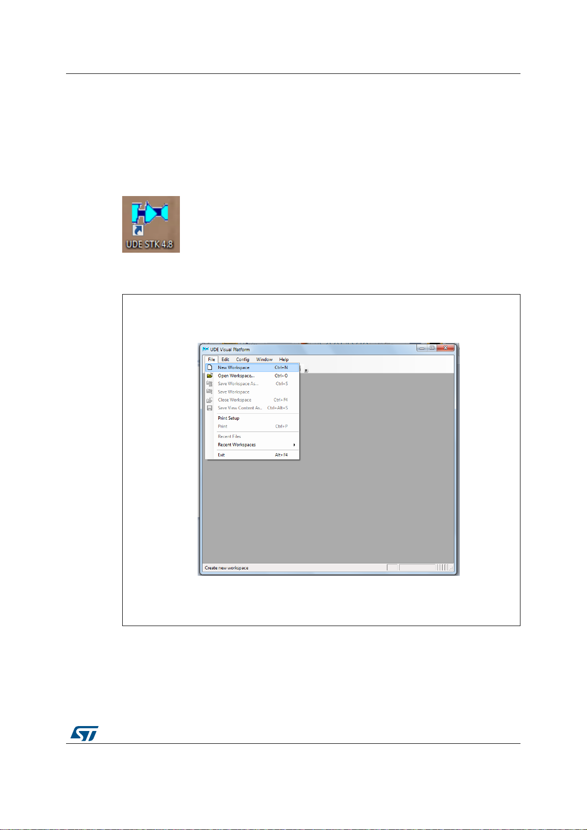
1. Start UDE Visual Platform 4.8
2. If not yet done, create a New Workspace for SPC56M. Click File>New Workspace
Figure 2. UDE: New Workspace creation
3. Name the new Workspace i.e. Monaco and select OPEN.

How to load general purpose FW on SPC56M-Discovery UM2266
8/14 DocID030871 Rev 2
Figure 3. UDE: workspace load
4. UDE Visual Platform 4.7 will be refreshed and new functionalities will appear, then click
on “Load Program” (or File/LoadProgramm)

DocID030871 Rev 2 9/14
UM2266 How to load general purpose FW on SPC56M-Discovery
12
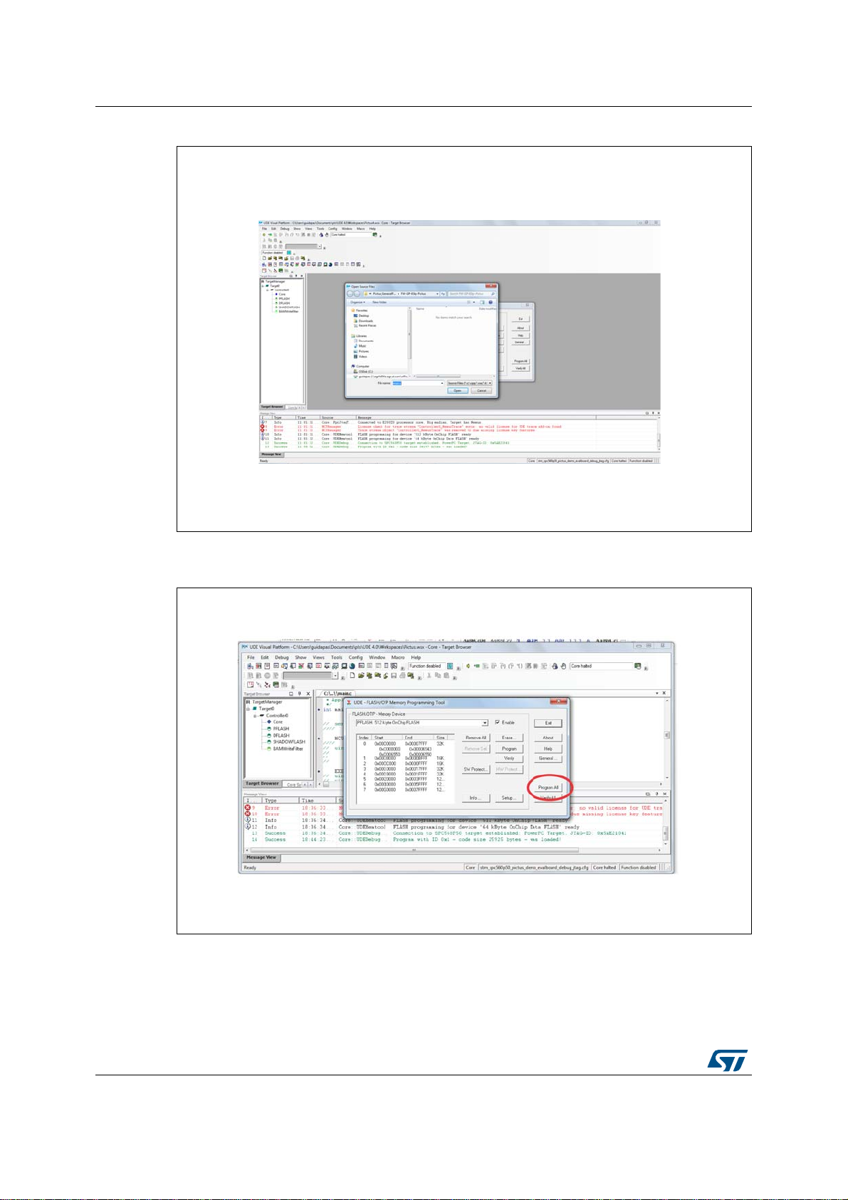
Figure 4. UDE: main interface
5. Browse the file L9177A and click “Open”
6. In the next windows click on “Cancel”
How to load general purpose FW on SPC56M-Discovery UM2266
10/14 DocID030871 Rev 2
Figure 5. UDE:.elf file loading
7. Then click on “Program All”.
Figure 6. UDE: program loading on Flash
8. The UDE Visual Platform 4.7 will start to load the program.

DocID030871 Rev 2 11/14
UM2266 How to load general purpose FW on SPC56M-Discovery
12
Figure 7. UDE: loading progress
9. When the procedure is terminated click on “Exit” on all windows
Figure 8. UDE: loading completed
10. When the procedure is terminated click on “Exit” on all windows and close UDE Visual
Platform 4.7. The SPC56M-Discovery is ready to be used with the Graphical User
Interface (GUI) for L9177A.
11. In order to connect to microcontroller board a RS232 cable is needed. In case your PC
has not COM port an adapter (i.e. USB-RS232) is needed. For the correct installation

How to load general purpose FW on SPC56M-Discovery UM2266
12/14 DocID030871 Rev 2
please refer to the documentation of the adapter. The cable has to be connected to the
COM0 port of SPC56M-Discovery.
DocID030871 Rev 2 13/14
UM2266 Revision history
13
1 Revision history
Table 1. Document revision history
Date Revision Changes
10-Oct-2017 1 Initial release.
08-Mar-2018 2 Updated document title.

UM2266
14/14 DocID030871 Rev 2
IMPORTANT NOTICE – PLEASE READ CAREFULLY
STMicroelectronics NV and its subsidiaries (“ST”) reserve the right to make changes, corrections, enhancements, modifications, and
improvements to ST products and/or to this document at any time without notice. Purchasers should obtain the latest relevant information on
ST products before placing orders. ST products are sold pursuant to ST’s terms and conditions of sale in place at the time of order
acknowledgement.
Purchasers are solely responsible for the choice, selection, and use of ST products and ST assumes no liability for application assistance or
the design of Purchasers’ products.
No license, express or implied, to any intellectual property right is granted by ST herein.
Resale of ST products with provisions different from the information set forth herein shall void any warranty granted by ST for such product.
ST and the ST logo are trademarks of ST. All other product or service names are the property of their respective owners.
Information in this document supersedes and replaces information previously supplied in any prior versions of this document.
© 2018 STMicroelectronics – All rights reserved
Table of contents


