Precautions
Name
and
Function
of
Each
Part
About
the
Quic!
Function
Table
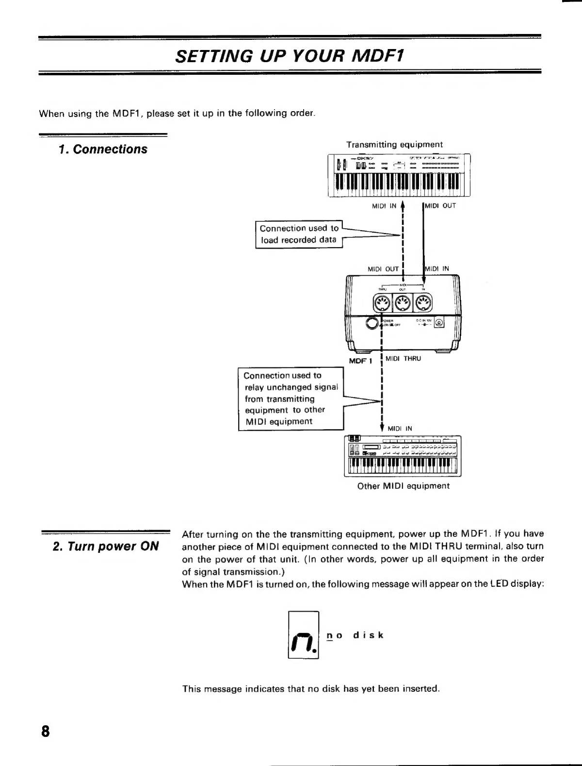
Setting
Up
Your
MDF1
..
TE
Error
Message
Table
Function
Guide.................
xe
MIDI
Implementation
Chart...
Initializing
Disks
(JOB
6:
Format)...
10
Storing
Data
(SAVE
mode)...
11
Checking
the
Total
Number
of
Files
(FIEE:mode)..
iere
etre
Fea
Feb
rea
ra
S
soe
erra
erar
14
Selecting
a
File
Number
(FILE
mode)..
i15
Loading
Data
(LOAD
mode)...
15
Displaying
the
Remaining
Disk
Space
(JOBADEREE:
DISK)
..:...
5
e
eden
dere
ica
Copying
a
File
(JOB
4:
COPY)
Copying
Disks
(JOB
5:
BACK
UP)..
s
Deleting
the
Final
File
(JOB
3:
DELETE)......................
20
ABOUT
THIS
MANUAL
Thank
you
very
much
for
purchasing
the
Yamaha
MIDI
Data
Filer
MDF1.
The
MDF1
is
an
extremely
practical
MIDI
Data
Recorder
capable
of
storing
various
types
of
MIDI
information
such
as
voice
data
from
a
DX-series
synthesizer
or
sequencing
data
from
OX-series
sequencers.
To
do
so,
it
uses
convenient
Quick
Disks,
which
measure
only
2,8
inches
across.
In
order
to
make
full
use
of
the
MDF1's
many
superb
features
and
to
ensure
years
of
satisfactory
service,
please
read
through
this
manual
carefully
before
operating
your
new
MIDI
Data
Filer.
FEATURES
*
The
MDF1
is
capable
of
storing
system
exclusive
messages
received
from
other
Yamaha
equipment
on
Quick
Disks.
The
following
are
examples
of
such
system
exclusive
messages:
*
Voice
data
and
performance
data
from
DX-series
synthesizers,
TX-series
tone
generators,
etc.
*
Sequence
data
from
OX-series
sequencers.
*
Pattern
data
and
song
data
from
RX-series
rhythm
machines.
*
A
maximum
of
59.9
kilobytes
of
data
(in
up
to
19
files)
can
be
stored
on
each
side
of
a
Quick
Disk.
*
The
MDF1
offers
a
host
of
practical
features
for
editing.
For
example,
you
can
delete
data,
check
the
remaining
disk
memory
space,
and
copy
data
to
other
disks.
*
Data
processing
is
much
faster
than with
conventional
cassette
data
recorders,
and
operation
is
simple
and
reliable.
CONTENTS
1
REFERENCE
MATERIAL
2
Specifications.................
6
MIDI
Data
Format.....................
7
Table
of
Displayed
Characters
k
Disk
Setting
the
Load
Time
Interval
for
Multiple
Data
(JOB
2:
INTERVAL
TIME)...
21
22
.
22
.
22
.
23