Stoelting O212 User manual


This manual provides basic information about the machine. Instructions and suggestions are
given covering its operation and care.
The illustrations and specifications are not binding in detail. We reserve the right to make
changes to the machine without notice, and without incurring any obligation to modify or pro-
vide new parts for machines built prior to date of change.
DO NOTATTEMPT to operate the machine until instructions and safety precautions in this
manual are read completely and are thoroughly understood. If problems develop or questions
arise in connection with installation, operation, or servicing of the machine, contact Stoelting.
Stoelting Foodservice Equipment
502 Highway 67
Kiel, WI 53042-1600
U.S.A.
Main Tel: 800.558.5807
Fax: 920.894.7029
Customer Service: 888.429.5920
Fax: 800.545.0662
© 2014 PW Stoelting, LLC
stoeltingfoodservice.com

Safety Alert Symbol:
This symbol Indicates danger, warning or caution.
Attention is required in order to avoid serious per-
sonal injury. The message that follows the symbol
contains important information about safety.
Signal Word:
Signal words are distinctive words used throughout
this manual that alert the reader to the existence and
relative degree of a hazard.
CAUTION
The signal word “CAUTION” indicates a potentially
hazardous situation, which, if not avoided, may result
in minor or moderate injury and equipment/property
damage.
A Few Words About Safety
Safety Information
Read and understand the entire manual before
operating or maintaining Stoelting equipment.
This manual provides the operator with information
for the safe operation and maintenance of Stoelting
equipment. As with any machine, there are hazards
associated with their operation. For this reason safety
is emphasized throughout the manual. To highlight
specific safety information, the following safety defini-
tions are provided to assist the reader.
The purpose of safety symbols is to attract your at-
tention to possible dangers. The safety symbols, and
their explanations, deserve your careful attention
and understanding. The safety warnings do not by
themselves eliminate any danger. The instructions
or warnings they give are not substitutes for proper
accident prevention measures.
If you need to replace a part, use genuine Stoelting
parts with the correct part number or an equivalent
part. We strongly recommend that you do not use
replacement parts of inferior quality.
WARNING
The signal word “WARNING” indicates a potentially
hazardous situation, which, if not avoided, may result
in death or serious injury and equipment/property
damage.
CAUTION
The signal word “CAUTION” not preceded by the
safety alert symbol indicates a potentially hazardous
situation, which, if not avoided, may result in equip-
ment/property damage.
NOTE (or NOTICE)
The signal word “NOTICE” indicates information or
procedures that relate directly or indirectly to the
safety of personnel or equipment/property.

SECTION DESCRIPTION PAGE
1. INTRODUCTION
1.1 Description............................................................................................................. 1
1.2 Specifications ........................................................................................................ 1
2. INSTALLATION INSTRUCTIONS
2.1 SafetyPrecautions ................................................................................................. 3
2.2 ShipmentandTransit.............................................................................................. 4
2.3 FreezerInstallation ................................................................................................. 4
2.4 InstallingPermanentWiring .................................................................................... 5
3. INITIAL SET-UP AND OPERATION
3.1 Operator'sSafetyPrecautions................................................................................ 7
3.2 OperatingControlsandIndicators........................................................................... 7
3.3 Sanitizing ............................................................................................................... 8
3.4 FreezeDownandOperation................................................................................... 9
3.5 MixInformation ....................................................................................................... 10
3.6 RemovingMixFromFreezer .................................................................................. 10
3.7 CleaningTheFreezer............................................................................................. 11
3.8 Disassembly of Freezer Parts ................................................................................ 11
3.9 CleaningThe FreezerParts.................................................................................... 12
3.10Sanitize FreezerandFreezerParts ....................................................................... 12
3.11AssemblyofFreezer ............................................................................................. 12
3.12RoutineCleaning................................................................................................... 13
3.13PreventiveMaintenance ........................................................................................ 15
3.14Extended Storage ................................................................................................. 16
4. TROUBLESHOOTING CHARTS................................................................................ 17
5. REFERENCE DRAWINGS......................................................................................... 20
5.1 Auger and Front Door Drawings ............................................................................ 20
5.2 Air Cooled Parts & Wiring Diagram....................................................................... 22
5.3 Water Cooled Parts & Wiring Diagram.................................................................. 29
5.4 General Parts List.................................................................................................. 35
TABLE OF CONTENTS

LIST OF ILLUSTRATIONS
FIGURE TITLE PAGE
1 ModelOptima212Freezer .................................................................................... 1
2 Specifications ........................................................................................................ 1
3 WarningLabelLocations ....................................................................................... 3
4 Leveling ................................................................................................................. 4
5 SpaceandVentilationRequirements ..................................................................... 4
6 Electrical Plug ....................................................................................................... 4
7 InstallingTrayandCover ........................................................................................ 4
8 PowerCordConnection ......................................................................................... 5
9 Controls ................................................................................................................. 7
10 MixInletRegulator ................................................................................................. 9
11 CleanControl......................................................................................................... 9
12 SanitizingHopper .................................................................................................. 9
13 DrainingSolution ................................................................................................... 9
14 DispensingProduct ...............................................................................................10
15 RemovingMixInletRegulator.................................................................................10
16 DrainingMix ..........................................................................................................11
17 RemovingFrontDoor .............................................................................................11
18 AugerShaftRemoval .............................................................................................12
19 Removing"O"Ring ................................................................................................12
20 CleaningFreezerBarrel .........................................................................................12
21 ExplodedViewofAuger .........................................................................................13
22 MixInletRegulator .................................................................................................13

1
SECTION 1
DESCRIPTION AND SPECIFICATIONS
1.1DESCRIPTION
The Stoelting Optima 212 floor model freezer is gravity
fed.The freezer is equipped with fully automatic controls
to provide a uniform product. The freezer is designed to
operate with almost any type of commercial shake mix
available.This manualis designedto assistqualified ser-
vicepersonnel and operatorsin theinstallation, operation
and maintenance of the Stoelting Model Optima 212
freezer.
Figure 1. Model Optima 212 Freezer
1.2SPECIFICATIONS
Figure 2. Specifications
/,67('5<6&

2
MODEL OPTIMA 212
FLOORMODEL
GRAVITYSHAKEFREEZER
DIMENSIONS:
Freezer: 17.6" (45cm) wide x 28.6" (73cm) deep x 63.75" (162cm) high
Crated: 19.5" (50cm) wide x 33" (84cm) deep x 40" (102cm) high
WEIGHT:
Freezer: 332lbs. (150kg) Crated: 427lbs. (193kg)
ELECTRICAL:
Description Optima 212-38
Voltage AC 1PH 208/230
Total Run Amps 10.5
Drive Motor 3/4 HP
Compressor 10,760BTUH (90°F -0°F)
Use 20 amp HACR circuit breaker.
Automatic safeguard circuit built into electronic control - protects major
freezercomponents underabnormal operating conditions.
COOLING:
Air cooled requires minimum 3" (7.6cm) air clearance on back side.
Noclearance needed onsides.
HOPPER:
6.25Gallons (23.7liters) refrigerated and insulated.

3
SECTION 2
INSTALLATION INSTRUCTIONS
2.1SAFETYPRECAUTIONS
Do not attempt to operate the freezer until the safety
precautionsandoperatinginstructionsinthismanualare
readcompletelyandarethoroughlyunderstood.
Takenoticeofallwarninglabelsonthefreezer.Thelabels
have been put there to help maintain a safe working
environment.Thelabelshavebeendesignedtowithstand
washing and cleaning. All labels must remain legible for
the life of the freezer. Labels should be checked periodi-
callytobesuretheycanberecognizedaswarninglabels.
Ifdanger,warningorcautionlabelsareneeded,indicate
the part number, type of label, location of label, and
quantityrequired along with your address and mailto:
STOELTING,INC.
ATTENTION: CustomerService
502 Hwy. 67
Kiel,Wisconsin 53042
Figure 3. Warning Label Locations

4
2.2SHIPMENTANDTRANSIT
Thefreezerhasbeenassembled,operatedandinspected
at the factory. Upon arrival at the final destination, the
completefreezermustbecheckedforanydamagewhich
mayhaveoccurredduringtransit.
With the method of packaging used, the freezer should
arriveinexcellentcondition.THECARRIERISRESPON-
SIBLE FOR ALL DAMAGE IN TRANSIT, WHETHER
VISIBLEORCONCEALED.Donotpaythefreightbilluntil
thefreezerhasbeencheckedfordamage.Havethecarrier
note any visible damage on the freight bill. If concealed
damageand/orshortageisfoundlater,advisethecarrier
within10daysandrequestinspection.Thecustomermust
place claim for damages and/or shortages in shipment
withthecarrier.Stoelting,Inc.cannotmakeanyclaims
against the carrier.
2.3FREEZERINSTALLATION
Installationofthefreezerinvolvesmovingthefreezerclose
to its permanent location, removing all crating, setting in
place,assembling parts,and cleaning.
A. Uncratethefreezer.
B. Accuratelevelingisnecessaryforcorrectdrainage
offreezerbarrelandtoinsurecorrectoverrun.Place
a spirit level on top of the freezer at each corner to
checkforlevelcondition.Ifadjustmentisnecessary,
level the freezer by turning the caster in or out and
tighten the locknut. (Fig. 4).
Figure 7. Installing Tray and Cover
Figure 4. Leveling
C. Thefreezerisequippedwithanaircooledcondenser
andrequirescorrectventilation.Thefrontofthe
freezeristheairintakeandtheback discharge. Both
front and back must have a minimum of 3" of
clearance.(Fig.5).
CAUTION
FAILURE TOPROVIDEADEQUATEVENTILATION
WILL VOID WARRANTY!
D. PlacetheOFF-ONswitchintheOFFposition.(Fig.10).
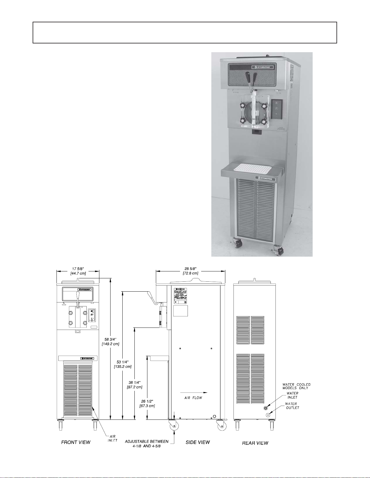
Figure 5. Space and Ventilation Requirements
E. Connectthepowercord.Theplugisdesignedfor208
or230volt/20ampduty.Checkthenameplateonyour
freezerforpropersupply.Theunitmustbeconnected
toaproperlygroundedreceptacle.Theelectricalcord
furnishedaspartof the freezerhasathree prong
groundingtypeplug(Fig.6).Theuseofanextension
cord is not recommended, if necessary use one with
asize12gaugeorheavierwithgroundwire.Donotuse
anadaptertogetaroundgroundingrequirement.
CAUTION
DONOTALTERORDEFORMPLUGINANYWAY!
F. Installthedriptray,draintray,hoppercoverandother
miscellaneous parts on the freezer. (Fig. 7).
Figure 6. Electrical Plug

5
2.4INSTALLINGPERMANENTWIRING
Ifpermanentwiringisrequiredbylocalcodes,thefollow-
ing procedure must be performed.
WARNING
DISCONNECT FREEZER FROM THE SOURCE
OF ELECTRICAL SUPPLY BEFORE SERVICING.
A. Removetheleftsidepanelandelectricalboxcover.
B. Disconnectthe wiresfrom theterminal
block. Disconnect the green ground wire from the
groundingstud. (Fig. 8).
Figure 8. Power Cord Connection
C. Remove the power cord.
D. Install permanent wiring according to local code.
E. Replace the electrical boxcover and left side panel.

6

7
SECTION 3
INITIAL SETUP AND OPERATION
3.1OPERATOR'SSAFETYPRECAUTIONS
SAFEOPERATION ISNOACCIDENT; Observe these
rules:
A. Know the freezer. Read and understand the
OperatingInstructions.
B. Notice all warning labels on the freezer.
C. Wear proper clothing. Avoid loose fitting gar-
ments,and remove watches,rings or jewelrywhich
could cause a serious accident.
D. Maintain a clean work area. Avoid accidents by
cleaning up the area and keeping it clean.
E. Stay alert at all times. Know which switch, push
button or control you are about to use and what
effect it is going to have.
F. Disconnect electrical cord for maintenance.
Neverattempt torepair or perform maintenance on
the freezer until the main electrical power has been
disconnected.
G. Do not operate under unsafe operating condi-
tions. Neveroperate thefreezer ifunusual orexces-
sivenoise orvibration occurs.
3.2OPERATINGCONTROLSANDINDICATORS
Beforeoperating the freezer, it is required that the
operatorknow the function of each operating control.
Referto Figure 9for the locationof the operating
controlson thefreezer. Forthe informationregarding
flashingindicator lights, referto the troubleshooting
section.
WARNING
THE OFF-ON SWITCH MUST BE PLACED IN THE OFF
POSITION WHEN DISASSEMBLING FOR CLEANING
OR SERVICING. THE FREEZER MUST BE DISCON-
NECTED FROM ELECTRICAL SUPPLY BEFORE RE-
MOVINGANY ACCESS PANEL.
Figure 9. Controls
High Pressure Cutout Switch Located Back of Freezer (Some Models)
ÊÊ
ÊÊ
Ê
OFF-ON
POWERSWITCH
HOLDREADY
SWITCH
PUSHTOFREEZE
CLEAN
MIX LOW
ÅÅ
ÅÅ
Å
ÅÅ
ÅÅ
Å
ÅÅ
ÅÅ
Å
ÈÈ
ÈÈ
È
ÇÇ
ÇÇ
ÇCONSISTENCY/TEMPERATURE
ADJUSTMENT
DISPENSERATE
ADJUSTMENT
ÈÈ
ÈÈ
È

8
A. SPIGOT SWITCH
The SPIGOT switch will automatically actuate the
augerdriveandrefrigerationsystemswhenthespigot
is opened to dispense product. When the spigot is
closed,thedrivemotorandcompressor will remain
"on"untiltheproductinthebarrelreachestheproper
temperature.
B. OFF-ONSWITCH
The OFF-ON switch is a two position toggle switch
usedto supplypower to thecontrol circuit.When the
switch is in the OFF position, nothing will run. When
the switch is in the ON position the freezer will be in
the idle mode until a switch is activated.
C. PUSHTOFREEZESWITCH
ThePUSHTOFREEZEswitchisa"snap"switchused
tostartthe freezing cycle.During initial freezedown,
theOFF-ONswitchisplacedintheONposition.Then
the PUSH TO FREEZE switch is pressed until the
drivemotorandcompressorcome"ON".
NOTE
After the gearmotor starts, there is a 3 second de-
lay before the compressor starts.
Duringthenormaloperation,theredPUSHTOFREEZE
switch light will illuminate after the freezer has been
idlefor thepreset cycles.Before drawingproduct,
pressthePUSHTOFREEZEswitchifitisilluminated.
Waituntilthegreenlightisilluminatedbeforedispens-
ing.
NOTE
If the freezer shuts off and the PUSH TO FREEZE
light flashes, you have an error condition. Turn the
OFF-ON swtich to the OFF position, correct the
problemandturnthe freezer backon.(SeeTrouble-
shooting.)
D. GREENLIGHT
Thegreenlightisusedtoindicatethattheproducthas
reachedthepropertemperatureandis ready tobe
dispensed.
NOTE
If the PUSH TO FREEZE red light is illuminated,
push the PUSH TO FREEZE switch and wait until
thegreen light illuminates before dispensing.
E. CLEANSWITCH
The CLEAN switch is a "snap" switch. When the
switchispushedtherefrigerationsystemwillbeOFF
andtheaugerwillrotateforcleaning.Whentheswitch
is pushed again, the auger will stop and the CLEAN
light will flash indicating the freezer is in the CLEAN
mode. To exit the CLEAN mode turn the OFF-ON
switch to the OFF position. If the freezer is left in
CLEAN for more than 30 minutes or is pushed three
timesintenseconds,itwillgoinerror.Toresetplace
the CLEAN-OFF-ON switch in the ON position and
allowtheerrorlighttoflashaminimumof10minutes.
Then turn to off, wait 5 seconds and turn on.
F. DRIVEMOTOROVERLOAD
TheinternalDRIVEMOTOROVERLOADwilltripifthe
drivemotorisoverloaded.Itwillresetafterapproxi-
mately10-12minutes.Ifthedrivemotorcontinuesto
trip,refertoTroubleshooting(Sec.4).
G. RED MIX LOW LIGHT
TheredMIXLOWlightisdesignedtoalerttheoperator
to a low mix condition. The light will illuminate with
approximatelyonegallonofmixinthehopper.When
theMIXLOWlightisilluminated,refillhopperimmedi-
ately. NOTE
Failure to refill hopper immediately may result in
operationalproblems.
H. HOLDREADYSWITCH
The HOLD READY switch is a push button switch.
Whenpushedinandheldfor5seconds,theholdready
modewillbeactivated.Theproductwillremainready
toserveandthefreezerwillnotgotoidle.Toreturnto
normaloperationpushand holdfor5seconds.
I. DISPENSERATEADJUSTER
Thedispense rate adjuster limits the opening of the
spigot. To adjust product dispense rate, turn the
adjustingknobclockwiseforslowerflowandcounter-
clockwisefor faster flow.
3.3 SANITIZING
Sanitizing must be done after the freezer is cleaned and
just before the hopper is filled with mix. Sanitizing the
night before is not effective. However, you should
always clean the freezer and parts after using it.
WARNING
THE UNITED STATES DEPARTMENT OF AGRI-
CULTUREAND THE FOODAND DRUGADMINIS-
TRATION REQUIRE THAT ALLCLEANING AND
SANITIZING SOLUTIONS USED WITH FOOD
PROCESSING EQUIPMENT BE CERTIFIED FOR
THIS USE.
Whensanitizingthefreezer,refertolocalsanitaryregula-
tions for applicable codes and recommended sanitizing
products and procedures. The frequency of sanitizing
must comply with local health regulations. Mix sanitizer
accordingtomanufacturer'sinstructionstoprovidea100
parts per million strength solution. Mix sanitizer in quan-
tities of no less than 2 gallons (7.5 liters) of 120°F water.
Allow sanitizer to contact the surfaces to be sanitized for
5minutes.Anysanitizermustbeusedonlyinaccordance
withthemanufacturer'sinstructions.
NOTE
Stoelting, Inc. has found that STERA-SHEEN
GREENLABEL SANITIZER ANDCLEANER does
aneffectivejob of properlysanitizing and cleaninga
soft serve freezer. We therefore include a sample
with each new freezer. Other products may be as
effective.For furtherinformationrefertocleaningand
sanitizinginformation Section 3.13.

9
E. Afterfiveminutes,placeabucketunderthespigotand
openspigottodrainsanitizingsolution.Whensolution
hasdrained,presstheCLEANsnapswitchtostopthe
auger.Allowthefreezer barrel to drain completely
(Fig.13).
Figure 10. Mix Inlet Regulator
Figure 12. Sanitizing Hopper
D. Cleansidesofhopper,mix inlet regulator andunder
sideofhoppercoverusingasanitizedsoftbristlebrush
dipped in the sanitizing solution. (Fig. 12).
Figure 11. Clean Control
CAUTION
PROLONGED CONTACT OF SANITIZER WITH
FREEZER MAY CAUSE CORROSION OF STAIN-
LESS STEEL PARTS.
In general, sanitizing may be conducted as follows:
A. Push the mix inlet regulator into hopper with air
inlet(long) tube towardthefrontofthefreezer
(Fig.10).
3.4 FREEZEDOWNANDOPERATION
This section covers the recommended operating proce-
durestobefollowedforthesafeoperationofthefreezer.
A. Sanitize just prior to use.
B. Place the OFF-ON switch in the OFF position.
C. With spigot open, pour approximately 1 gallon (3.8
liters)ofmixintothehopper.Allowthemixtoflushout
about8ounces(0.23liters)ofsanitizingsolutionand
liquid mix. Close the spigot.
D. Fill hopper with approximately 5 gallons (19 liters) of
pre-chilled(40°For4°C)mix.
CAUTION
DO NOT OVERFILL THE HOPPER. MIX LEVEL
MUST NOT BE HIGHER THAN THE AIR INLET
TUBE ON THE MIX INLET REGULATOR.
E. Thefreezerbarrelwillautomaticallyfilluntilitisabout
1/2full.Iffreezerbarreldoesnotfill,checkforobstruc-
tioninthemixinletregulator.Iffreezerbarrelfillsover
1/2 full, check for leaks at the mix inlet regulator "O"
Ring or check if the mix inlet regulator was installed
correctly or that the freezer is level.
F. Place the OFF-ON switch in the ON position, then
pressthePUSHTOFREEZEswitchuntilthefreezer
starts.
NOTE
After the gearmotor starts, there is a 3 second de-
lay before the compessor starts.
Figure 13. Draining Solution
B. Prepare 4gallons (15 liters) of sanitizingsolution
followingmanufacturer'sinstructions.Pourintohop-
per with mix inlet regulator in place.
C. Place the OFF-ON toggle switch in the ON position
while pressing the CLEAN switch. Check for leaks.
(Fig.11.)

10
G. After about 7 to 10 minutes the freezer will shut OFF
andthegreenlightwillilluminateindicatingtheproduct
isreadytoserve.Freezedowntimemaybelongerfor
somemixes.Highambienttemperaturesmayextend
freezedowntime.
H. Fornormaldispensing,movethespigothandlefully
open.(Fig.14).
Proper product serving temperature varies from one
manufacturer's mix to another. Shake mixes range from
24° to 28°F (-4° to -2°C).
When checking the temperature, stir the thermometer in
thefrozenproducttoreadthetruetemperature.
Mix does not improve with age. Old mix, or mix that has
been stored at too high temperature, can result in a
finished product that is less than satisfactory from the
appearanceandtastestandpoint.Toretardbacteriagrowth
indairybasedmixes,thebeststoragetemperaturerange
is between 36° to 40°F (2.2° to 4.4°C).
Some products tend to foam more than others. If excess
foam should occur, skim off with a sanitized utensil and
discard. Periodically, stir the mix in the hopper with a
sanitized utensil.
3.6 REMOVINGMIXFROMFREEZER
Toremovethemixfromthefreezer,refer to the following
steps:
A. Removethemixinletregulatorfromthehopperby
pulling straight up (Fig. 15).
B. Place the OFF-ON rocker switch in the ON position
andpushtheCLEANswitchtorotatetheauger.Allow
the mix to agitate in freezer barrel about 5 minutes.
CAUTION
REFRIGERATION IS AUTOMATICALLY ACTI-
VATED WHEN THE SPIGOT IS OPENED. CLOSE
THE SPIGOT COMPLETELY AFTER DISPENS-
ING.
I. The freezer is designed to dispense the product at a
reasonabledrawrate.Ifthefreezerisoverdrawn,the
resultisaverythinproduct.Ifthisshouldoccur,allow
thefreezertorunforapproximately30secondsbefore
dispensingadditionalproduct.Afterawhiletheopera-
torwill senseor feelwhen thefreezer is beginning to
fallbehind, and will slow down on the rateof draw so
as not to exceed the capacity.
J. DonotoperatethefreezerwhentheMIXLOWlightis
onorwithlessthan1-3/4inches(4.4cm)ofmixinthe
hopper.Refillthehopperimmediately.
3.5 MIXINFORMATION
Mix can vary considerably from one manufacturer to
another.Differencesintheamountofbutter-fatcontentand
quantity and quality of other ingredients have a direct
bearingonthefinishedfrozenproduct.Achangeinfreezer
performance that cannot be explained by a technical
roblem may be related to the mix.
Figure 15. Removing Mix Inlet Regulator
(Shown with no mix in hopper)
Figure 14. Dispensing Product

11
Figure 16. Draining Mix
C. Emptythefreezerbyopeningthespigotanddraining
into a bucket. (Fig. 16).
D. Place the OFF-ON switch in the OFF position.
B. Removethemixinletregulatorfromthehopperby
pullingstraightup.
C. Removethefrontdoorbyturningoffthecircularknobs
and then pulling the front door off the studs.
D. Removethespigotbodyfromthefrontdoorbypushing
the spigot body through the bottom of the door.
Removeaugersupportbushing.
Figure 17. Removing Front Door
3.7 CLEANINGTHEFREEZER
NOTE
The frequency of cleaning the freezer and freezer
parts must comply with local health regulations.
After the mix has been removed from the freezer, the
freezermustbecleaned.Tocleanthefreezer,refertothe
followingsteps:
A. Closethespigotandfillthehopperwith 4 gallons (15
liters) of cold tap water.
B. Place the OFF-ON switch in the ON position while
pushing the CLEAN switch to rotate the auger.
C. Allowthewatertoagitateforapproximately5minutes.
NOTE
Iffreezer is left in CLEANfor morethan 30 minutes,
it will go to error.
D. Openthespigottodrainthewater.Remembertoplace
a bucket or container under the spigot to catch the
water.Whenthewaterhasdrained,turntheOFF-ON
switchtotheOFFposition.Allowthefreezerbarrelto
draincompletely.
E. RepeatStepsAthroughDusingawarm(120°F)mild
detergent(Joyorequivalent) solution.
3.8 DISASSEMBLYOFFREEZERPARTS
CAUTION
PLACE THE OFF-ON TOGGLE SWITCH IN THE
OFF POSITION BEFORE DISASSEMBLING FOR
CLEANINGOR SERVICING.
Inspection for worn or broken parts should be made at
every disassembly of the freezer for cleaning or other
purposes.Allworn or brokenpartsshould bereplacedto
ensuresafety to boththe operator andthe customer and
tomaintaingoodfreezerperformanceandaqualityprod-
uct.Twonormalwearareasaretheaugerflightsandfront
auger support. Frequency of cleaning must comply with
thelocal healthregulations.
Todisassemble the freezer,refer tothe followingsteps:
A. Removehoppercoveranddraintray(Fig.17).

12
B. Washthehopperandfreezerbarrelwithwarm(120°F)
detergent(Joyorequivalent)waterandbrushes
provided.(Fig.20).
C. Cleanthedriptrayandinsertwithadetergent(Joyor
equivalent)solution.Rinsewithcleanhot(135°F)
water.
3.10SANITIZEFREEZERANDFREEZERPARTS
A. Use a sanitizing solution of 100 parts per million to
sanitize the parts before assembly.
B. Placeallpartsinthesanitizingsolution,thenremove
and let air dry.
C. Using this sanitizing solution and the large barrel
brushprovided,sanitizetherearofthebarrelby
dipping the brush in the sanitizing solution and
brushing.
3.11ASSEMBLYOFFREEZER
Toassemblethefreezerparts,refertothefollowingsteps:
NOTE
Petro-Gel sanitary lubricant or equivalent must be
used when lubrication of parts is specified.
NOTE
The United States Department of Agriculture and
theFood and DrugAdministration require thatlubri-
cantsused on foodprocessing equipment be certi-
fied for this use. Use lubricants only in accordance
withthe manufacturer's instructions.
Figure 20. Cleaning Freezer Barrel
E. Removetheaugerassemblyfromthefreezer(Fig.18).
Keep the rear of the auger shaft tipped up once it is
clearofthefreezertoavoiddroppingrearseal.
Figure 19. Removing "O" Ring
F. Removescaperblades and therearsealassembly.
G. Wipesocketlubricantfromthedriveend(rear)ofthe
auger with a cloth or paper towel.
H. Removeall"O"Ringsfrompartsbyfirstwipingoffthe
lubricantusingacleanpapertowel.Thensqueezethe
"O"Ringupwardwithadrycloth(Fig.19).Whenaloop
is formed, roll out of the "O" Ring groove.
WARNING
DONOT USE ANY TYPE OFSHARP OBJECT TO
REMOVE THE "O" RINGS.
3.9 CLEANINGTHEFREEZERPARTS
Placeall looseparts in a pan or container and take tothe
washsink forcleaning.Tocleanfreezerpartsrefertothe
followingsteps:
A. Placeallpartsinwarm(120°F)milddetergent(Joyor
equivalent)waterandcleanwithbrushesprovided.
Rinse all parts with clean hot (135°F) water.
CAUTION
DO NOT DAMAGE PARTS BY DROPPING OR
ROUGHHANDLING.

13
A. Assembleall"O"Ringsontopartsdry,withoutlubri-
cation.Thenapplyathinfilmofsanitarylubricationto
exposed surfaces of the "O" Rings. Also apply
athinfilmofsanitarylubricantinsideandoutsideofthe
frontaugersupportbushing.
B. Assemble the rear seal onto the auger with the large
endtotherear.Besurethe"O"Ringisinplacebefore
installing the rear seal.
C. Lubricatetheaugerdrive(rear)withasmallamountof
white socket lubricant. A container of socket lubri-
cant is shipped with the freezer.
CAUTION
DO NOT PLACE THE MIX INLET REGULATOR
INTO THE HOPPER BEFORE INSTALLING THE
AUGER.
D. Install the two plastic flights onto the auger and
insertintofreezerbarrel.
E. Rotate slowly until the augerengagesthedriveshaft.
F. Installtheauger supportbushingintothe front door.
G. Install the spigot body with "O" Rings into the front
door from bottom. Push straight up until the spigot is
in place.
H. Installthefrontdooronthe freezer.
I. Install the circular knobs on the freezer studs and
tightenhandtight.
CAUTION
TIGHTEN THE CIRCULAR KNOBS EVENLY. DO
NOTOVERTIGHTENKNOBS.
Look for the proper seal between the freezer barrel, "O"
Ring,andfrontdoor.
J. Install the mix inlet regulator into the freezer with the
air tube to the front of the freezer (Fig. 22).
K. Install hoppercoveranddraintrayand drip traywith
insert.
Figure 22. Mix Inlet Regulator
3.12ROUTINECLEANING
To remove spilled or dried mix from the freezer exterior,
simplywashinthedirectionofthefinishwithwarmsoapy
waterandwipedry.Do notusehighlyabrasivematerials
as they will mar the finish.
Figure 21. Exploded View of Auger
(Front Door and Related Parts)

14
CLEANINGvs.SANITIZING
It is important to distinguish between cleaning and
sanitizing. Although these terms may sound
synonymous,they are not. BOTH are requiredfor
adequatefoodsafetyandpropermachine
maintenance.
CLEANING
· Isthe removal ofsoil materialsfrom asurface.
· Isaprerequisiteforeffectivesanitizing.
NOTE
An UNCLEAN surface will harbor
bacteria that can defy sanitizing efforts.
Bacteriacandevelop andresistsanitizingefforts
within a layer of soil material (milkstone). Thorough
cleaningproceduresthatinvolvemilkstone
removalare criticalforoperatorsof frozen
dessertmachines.
SANITIZING
· Kills bacteria.
· Canbeeffectiveoncleansurfacesonly.
·DOESNOT cleanorremovemilkstone.
NOTE
Using a SANTITIZER onan uncleansurface will not
guaranteeacleanandsafefrozendessertmachine.
Proper Daily Maintenance:
The Only Way to Assure Food Safety and
ProductQuality
Properdailymaintenancecaninvolveawidevariety
ofproductsandprocedures. Overall,theproducts
andproceduresfallintothreeseparatecategories.
(Please note that this is a brief overview intended for
informationalpurposesonly.)
1. CLEANING–Thisinvolvesdrainingmixfromthe
freezerbarrelandrinsingthemachinewith
water. Next, a cleaner is run through the
machine. Then, the machine is disassembled
andremovable partsare takento the sink for
cleaning.
2. MILKSTONE REMOVAL –Since almostall
cleanersdonothavetheabilitytoremove
milkstone, the use of a delimer becomes
necessary. Although this procedure may not be
needed on a daily basis, it will usually follow the
cleaningprocedure. Itrequireslettinga delimer
solution soak in the machine for an extended
periodoftime. Individual parts arealsosoaked
inadeliming solution foranextended periodof
time(moreabout delimersinAdditional
Information).
It is recommended that a maintenance schedule be fol-
lowedtokeepthefreezercleanandoperatingproperly.
A. Cleaning and Sanitizing Information
Softservefreezersrequirespecialconsideration
whenit comesto foodsafety and proper cleaning
andsanitizing.
Thefollowinginformationhasbeencompiledby
PurdyProductsCompany,makersofStera-Sheen
GreenLabelCleaner/Sanitizerandspecifically
coversissuesforcleaningandsanitizingfrozen
dessert machines. This information is meant to
supplementacomprehensivefoodsafetyprogram.
Soil Materials Associated with Frozen Dessert
Machines
MILKFAT/BUTTERFAT–Ascomponentsofice-
cream/frozen custard mix, these soils will
accumulateon theinterior surfacesof the machine
and its parts. Fats are difficult to remove and help
attributeto milkstonebuild-up.
MILKSTONE – Is a white/gray film that forms on
equipment and utensils that come in contact with
dairy products. These films will accumulate slowly
onsurfacesbecauseofineffectivecleaning,useof
hard water, or both. Milkstone is usually a porous
deposit, which will harbor microbial
contaminantsandeventuallydefysanitizing
efforts.
Once milkstone has formed, it is very difficult to
remove. Withoutusing the correctproduct and
procedure, it is nearly impossible to remove a thick
layer of milkstone.
(NOTE:general-purposecleanersDONOTremove
milkstone.) This can lead to high bacteria counts
anda food safety dilemma.
IT IS BEST TO CONTROL MILKSTONE ON A
DAILYBASISBEFOREITCANBECOMEA
SIGNIFICANTFOODSAFETYPROBLEM.
In addition to food safety, milkstone can cause
prematurewear tomachine parts which can add to
costs for replacement parts or possibly more
expensiverepairsifwornmachinepartsarenot
replacedoncetheyhavebecomeexcessivelyworn.
Important Differences Between Cleaning and
Sanitizing
Table of contents
Other Stoelting Beverage Dispenser manuals
Popular Beverage Dispenser manuals by other brands

Krups
Krups BEERTENDER VB2158 user manual

Bunn
Bunn FMD-2 Illustrated parts catalog

Grindmaster
Grindmaster Crathco PM4-B Operation and instruction manual

Multiplex
Multiplex N2-Fusion ND21TS00 Installation, operation & maintenance manual

Grindmaster
Grindmaster Crathco G-Cool Single C-1S Specifications

CombiSteel
CombiSteel 7065.0005 user manual