Stoelting CBE117 User manual

Model CBE
OPERATORS MANUAL
Manual No. 513850 Rev.2


This manual provides basic information about the machine. Instructions and suggestions are
given covering its operation and care.
The illustrations and specifications are not binding in detail. We reserve the right to make
changes to the machine without notice, and without incurring any obligation to modify or pro-
vide new parts for machines built prior to date of change.
DO NOTATTEMPT to operate the machine until instructions and safety precautions in this
manual are read completely and are thoroughly understood. If problems develop or questions
arise in connection with installation, operation, or servicing of the machine, contact Stoelting.
Stoelting Foodservice Equipment
502 Highway 67
Kiel, WI 53042-1600
U.S.A.
Main Tel: 800.558.5807
Fax: 920.894.7029
Customer Service: 888.429.5920
Fax: 800.545.0662
© 2015 PW Stoelting, LLC
stoeltingfoodservice.com
Clearbowl Service Information:
888.429.5920 (U.S. toll free)
920.894.2293 (outsude the U.S.)

Safety Alert Symbol:
This symbol Indicates danger, warning or caution.
Attention is required in order to avoid serious per-
sonal injury. The message that follows the symbol
contains important information about safety.
Signal Word:
Signal words are distinctive words used throughout
this manual that alert the reader to the existence and
relative degree of a hazard.
CAUTION
The signal word “CAUTION” indicates a potentially
hazardous situation, which, if not avoided, may result
in minor or moderate injury and equipment/property
damage.
A Few Words About Safety
Safety Information
Read and understand the entire manual before
operating or maintaining Stoelting equipment.
This manual provides the operator with information
for the safe operation and maintenance of Stoelting
equipment. As with any machine, there are hazards
associated with their operation. For this reason safety
is emphasized throughout the manual. To highlight
specific safety information, the following safety defini-
tions are provided to assist the reader.
The purpose of safety symbols is to attract your at-
tention to possible dangers. The safety symbols, and
their explanations, deserve your careful attention
and understanding. The safety warnings do not by
themselves eliminate any danger. The instructions
or warnings they give are not substitutes for proper
accident prevention measures.
If you need to replace a part, use genuine Stoelting
parts with the correct part number or an equivalent
part. We strongly recommend that you do not use
replacement parts of inferior quality.
WARNING
The signal word “WARNING” indicates a potentially
hazardous situation, which, if not avoided, may result
in death or serious injury and equipment/property
damage.
CAUTION
The signal word “CAUTION” not preceded by the
safety alert symbol indicates a potentially hazardous
situation, which, if not avoided, may result in equip-
ment/property damage.
NOTE (or NOTICE)
The signal word “NOTICE” indicates information or
procedures that relate directly or indirectly to the
safety of personnel or equipment/property.

Section Description Page
1 Description and Specifications
1.1 Description..................................................................................................1
1.2 Specifications .............................................................................................2
2 Installation Instructions
2.1 Safety Precautions .....................................................................................3
2.2 Shipment and Transit..................................................................................3
2.3 Machine Installation....................................................................................3
3 Initial Set-Up and Operation
3.1 Operator’s Safety Precautions....................................................................5
3.2 Operating Controls and Indicators..............................................................5
3.3 Assembly of Machine .................................................................................6
3.4 Sanitizing....................................................................................................7
3.5 Freeze Down and Operation ......................................................................7
3.6 Removing Mix From Machine.....................................................................8
3.7 Disassembly of Machine Parts...................................................................8
3.8 Cleaning and Sanitizing the Machine Parts................................................8
3.9 Routine Cleaning........................................................................................9
3.10 Preventative Maintenance..........................................................................9
4 Settings
4.1 Making Adjustments ...................................................................................11
4.2 Settings.......................................................................................................11
5 Troubleshooting
5.1 Control Alarms............................................................................................13
5.2 Pressure Switch..........................................................................................13
6 Replacement Parts
6.1 Decals.........................................................................................................15
6.2 Tank and Cover ..........................................................................................15
6.3 Handle Assembly and Auger Parts.............................................................16
TABLE OF
CONTENTS


Owner’s Manual #513850 Rev.2 1 CBE Model Machines
SECTION 1
DESCRIPTION AND SPECIFICATIONS
1.1 DESCRIPTION
The CBE counter machines are equipped with fully au-
tomatic controls to provide a uniform product. They will
operatewithalmostanytypeoffrozenbeveragemix.This
manualisdesignedtohelpqualifiedservicepersonneland
operatorswiththeinstallation,operationandmaintenance
of the CBE machines.
ThismanualappliestoallCBEmodelmachinesinsingle,
double and triple tank configurations.
Figure 1-1 Model CBE117-37
Figure 1-2 Model CBE127-37
Figure 1-3 Model CBE167-37

Owner’s Manual #513850 Rev.2 2 CBE Model Machines
1.2 SPECIFICATIONS
Model CBE117 Model CBE127 Model CBE167
Dimensions Machine Machine Machine
width 9-1/2’’ (24,1 cm) 16-1/8’’ (41,0 cm) 24-1/2’’ (62,2 cm)
height 30-3/4’’ (78,1 cm) 30-3/4’’ (78,1 cm) 30-3/4’’ (78,1 cm)
depth 22’’ (55,9 cm) 22’’ (55,9 cm) 22’’ (55,9 cm)
Weight 71 lbs (32,2 kg) 119 lbs (53,9 kg) 148 lbs (67,1 kg)
Electrical 1 Phase, 115 VAC, 60Hz 1 Phase, 115 VAC, 60Hz 1 Phase, 115 VAC, 60Hz
running amps 11A 12A 12A
connection type NEMA5-15P included NEMA5-15P included NEMA5-15P included
Compressor 607 Btu/hr 1420 Btu/hr 1420 Btu/hr
Drive Motor 1/12 hp 1/12 hp per tank 1/12 hp per tank
Cooling Air cooled units require
10” air space on both
sides and back
Air cooled units require
10” air space on both
sides and back
Air cooled units require
10” air space on both
sides and back
Capacity 3.17 gallons 3.17 gallons per tank 3.17 gallons per tank

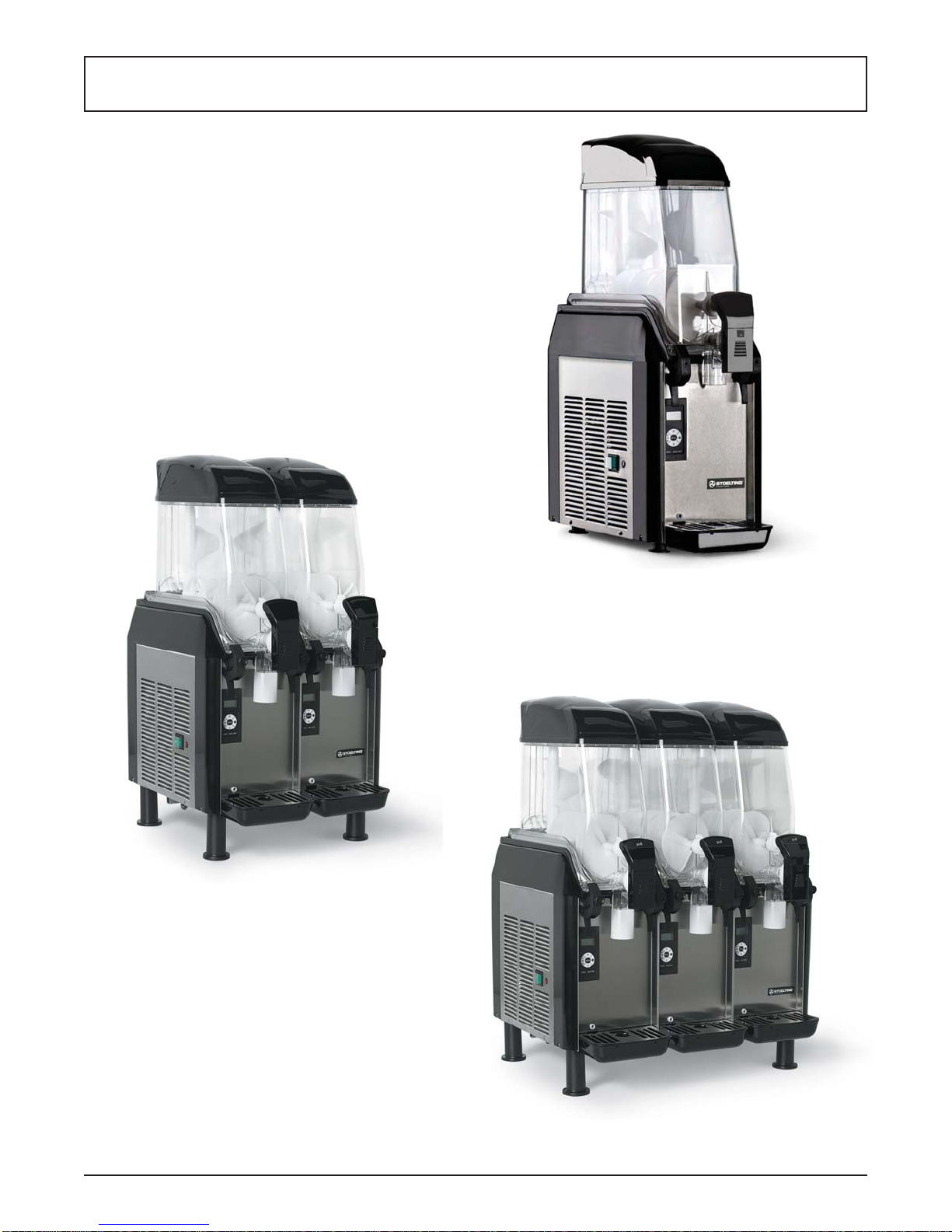
Owner’s Manual #513850 Rev.2 3 CBE Model Machines
SECTION 2
INSTALLATION INSTRUCTIONS
2.1 SAFETY PRECAUTIONS
Do not attempt to operate the machine until the safety
precautionsand operating instructions in this manual are
read completely and are thoroughly understood.
Take notice of all warning labels on the machine. The la-
bels have been put there to help maintain a safe working
environment.Thelabelshavebeendesignedtowithstand
washing and cleaning. All labels must remain legible for
thelifeofthemachine.Labelsshouldbecheckedperiodi-
callytobesuretheycanberecognizedaswarninglabels.
If danger, warning or caution labels are needed, indicate
thepartnumber,typeoflabel,locationoflabel,andquantity
required along with your address and mail to:
STOELTING, INC.
ATTENTION: Customer Service
502 Hwy. 67
Kiel, Wisconsin 53042
2.2 SHIPMENT AND TRANSIT
Themachinehasbeenassembled,operatedandinspected
at the factory. Upon arrival at the final destination, the
entire machine must be checked for any damage which
may have occurred during transit.
With the method of packaging used, the machine should
arriveinexcellentcondition.THECARRIERISRESPON-
SIBLE FOR ALL DAMAGE IN TRANSIT, WHETHER
VISIBLE OR CONCEALED. Do not pay the freight bill
until the machine has been checked for damage. Have
the carrier note any visible damage on the freight bill. If
concealeddamageand/orshortage is found later,advise
the carrier within 10 days and request inspection. The
customermustplaceclaimfordamagesand/orshortages
in shipment with the carrier. Stoelting, Inc. cannot make
any claims against the carrier.
2.3 MACHINE INSTALLATION
Installation of the machine involves moving the machine
close to its permanent location, removing all crating, set-
ting in place, assembling parts, and cleaning.
A. Uncrate the machine.
B. Remove the packing material and move the
machine into place. Do not lift the machine by
the augers or handles. Only lift by grasping the
bottom of the machine.
C. Installthe legs.Therearlegshavea nutscrewed
onto the bolt which increases the height so the
machine tilts slightly forward.
D. Correctventilationisrequired.TheCBEmachine
requires 10” clearance on both sides and 12”
clearance at the back.
E. Install the drip trays.
NOTE
The drip trays can be connected to a floor drain.
Punch out one of the holes at the back of the tray
and connect tubing to the tray.
G. Make sure the Main Power Switch is in the Off
position.
H. Connect the power cord to the proper power
supply. Check the nameplate on on front of the
machine for the required power supply. The
unit must be connected to a properly grounded
receptacle. The electrical cord furnished as part
of the machine has a three prong grounding
type plug. The use of an extension cord is not
recommended, if necessary use one with a size
12gaugeorheavierwithgroundwire.Donotuse
anadaptertogetaroundgroundingrequirement.
I. Clean and sanitize the machine before the first
use.
CAUTION
Do not install the machine outdoors. Exposure to
weather conditions or wet and damp locations can
damage the machine
WARNING
Do not alter or deform electrical plug in any way.
Alteringtheplugto fit into an outlet of differentcon-
figuration may cause fire, risk of electrical shock,
product damage and will void warranty.

Owner’s Manual #513850 Rev.2 4 CBE Model Machines

Owner’s Manual #513850 Rev.2 5 CBE Model Machines
SECTION 3
INITIAL SET-UP AND OPERATION
3.1 OPERATOR’S SAFETY PRECAUTIONS
SAFE OPERATION IS NO ACCIDENT; observe these
rules:
A. Know the machine. Read and understand the
Operating Instructions.
B. Notice all warning labels on the machine.
C. Wear proper shoes and clothing. Avoid loose
fitting garments, and remove watches, rings or
jewelry that could cause a serious accident. Do
not operate with wet hands or feet.
D. Do not allow children to use the machine.
E. Maintain a clean work area. Avoid accidents by
cleaning up the area and keeping it clean.
F. Stay alert at all times. Know which switch, push
button or control you are about to use and what
effect it is going to have.
G. Disconnectelectricalcordformaintenance.Never
attempt to repair or perform maintenance on the
machineuntilthemainelectricalpowerhasbeen
disconnected. Unplug the machine at the plug.
Do not pull the electrical cord to disconnect the
machine from the power source.
H. Donotoperateunderunsafeoperatingconditions.
Neveroperatethemachineifunusualorexcessive
noise or vibration occurs.
3.2 OPERATING CONTROLS AND INDICATORS
Before operating the machine, it is required that the op-
erator know the function of each operating control. Refer
to Figure 3-1 for the location of the operating controls on
the machine.
A. Main Power Switch
The Main Power Switch is used to control the
operation of the refrigeration system and the
augers. When the switch is in the Off position,
power will not be supplied to the control board,
refrigeration system or augers. Place it in the On
position for normal operation.
Figure 3-1 Controls
Main Power
Switch
Spigot
Lock
WARNING
High voltage will shock, burn or cause death. The
Main Power switch must be placed in the Off posi-
tionpriortodisassembling for cleaning orservicing.
Do not operate machine with the panels removed.

Owner’s Manual #513850 Rev.2 6 CBE Model Machines
B. Control Board
Auger Movement
TheAugerMovementbuttoncontrolstheoperation
oftheaugers.Theaugersmustberotatingtostart
the refrigeration cycle.
Menu
The Menu button is used to modify machine
settings. Press and hold the Menu button for two
seconds to access the settings. Press the Menu
button to scroll through each option.
Cold Selection
The Cold Selection button will change the
refrigerationcycledependingontheproducttype
selected.Pressthe<<>>buttontotogglebetween
standby and the two product types. The display
will show an ice crystal (asterisk) for slush and
water drops (three dots) for cold drink.
Arrow Buttons
The Arrow Buttons are used to change the
consistencyortemperatureoftheproduct.Inslush
mode, the consistency can be changed from 1
(lowest consistency) to 9 (highest consistency).
In cold drink mode, the temperature can be
changedfrom2(lowesttemperature)to5(highest
temperature).
D. Spigot Lock
The Spigot Lock is a lever located behind the
spigot handle that will lock the spigot handle in
the open or closed position. When the spigot is
in the desired position, push the lever clockwise
to lock it in place. Unlock the spigot by moving
the lever counterclockwise.
E. Minimum Level Sensor
The minimum level sensor is located at the back
of the tank. When the product level in the tank
dropsbelowtheprobefor20minutesthedisplay
will flash for 20 seconds every 20 minutes until
the tank is refilled. If the LowLevel setting is on
(Section4.2)thedisplaywillgivealowmixwarning
and the slush consistency will change to 2 until
the tank is refilled.
NOTE
Failure to refill the tank immediately may result in
operational problems.
3.3 ASSEMBLY OF MACHINE
All parts should be cleaned, sanitized and allowed to air
dry before assembling.
ToAssemblethemachineparts,refertothefollowingsteps:
A. Press the gear into bottom of the vertical auger
and install the auger. Secure it to the machine
with the fastening nut.
Cold
Selection
Auger
Movement
Menu
Arrow
Buttons
Figure 3-2 Control Board
CAUTION
Pinch Point
When the spigot handle is locked in the open po-
sition it can pinch and cause injury. Do not place
your hand between the spigot handle and spigot
assembly when it is locked in the open position.
Figure 3-3 Installing Augers
Vertical
Auger
Horizontal
Auger
Gear
Gear
Fastening
Nut

Owner’s Manual #513850 Rev.2 7 CBE Model Machines
B. Press the gear onto the back of the horizontal
auger and install the auger.
C. Place the gasket into the bottom groove on the
tank. Make sure the joint of the gasket is on one
of the two rear corners of the tank.
D. Install the tank onto the machine and secure it
with the tank clamps. Screw the tank fastening
knobs into the tank clamps.
E. Installtheaugersupportknobandturnitclockwise
to lock it into place.
F. Install the spigot assembly and turn it clockwise
to lock it into place. The assembly will click when
it is fully tightened.
G. Install the handle onto the spigot assembly with
an upward motion.
H. Install the handle cover onto the handle with an
upward motion.
3.4 SANITIZING
Sanitizingmustbedoneafterthemachineiscleanedand
justbeforethehopperisfilledwithmix.Sanitizingthenight
beforeisnoteffective.However,youshouldalwaysclean
the machine and parts after each use.
The United States Department of Agriculture and
the Food and Drug Administration require that all
cleaning and sanitizing solutions used with food
processing equipment be certified for this use.
Whensanitizingthe machine,refertolocal sanitary regu-
lationsforapplicablecodes andrecommended sanitizing
products and procedures. The frequency of sanitizing
must comply with local health regulations.
Mix sanitizer according to manufacturer’s instructions to
provide a 100 parts per million (ppm) strength solution
and check the solution with chlorine test strips. Allow
sanitizer to contact the surfaces to be sanitized for 5
minutes. Any sanitizer must be used only in accordance
with the manufacturer’s instructions.
In general, sanitizing may be conducted as follows:
A. Prepare Stera-Sheen Green Label Sanitizer
or equivalent according to manufacturer’s
instructionstoprovidea100ppmstrengthsolution.
Mix the sanitizer in quantities of no less than
2 gallons of 90° to 110°F (32° to 43°C) water.
Checkthestrengthofthesanitizingsolution.Use
a chlorine test strip and color chart to make sure
the solution has 100 ppm.Any sanitizer must be
usedonlyinaccordance with the manufacturer’s
instructions.
B. Pour the sanitizing solution into the tank.
C. PresstheMainPowerSwitchtoturnthemachine
on. Press the Auger Movement Switch to start
the auger. Make sure the display reads Motor
On. Check for leaks.
NOTE
Make sure the display reads Motor On. If it does
not, press the Cold Selection button until it does.
D. Clean sides of the tank, the vertical auger and
underside of tank cover using a clean soft bristle
brush dipped in the sanitizing solution.
E. After five minutes, place a container under the
spigot and open spigot to drain most sanitizing
solution. Leave a small amount of the sanitizing
solution in the freezing cylinder. Press theAuger
Movement button to stop the auger.
F. Collect the remaining sanitizing solution in a cup
andtestthechlorinecontentswithanewteststrip.
A reading of 100 ppm or more is acceptable.
If the reading is less than 100 ppm, sanitize the
machine again.
Ifthereadingislessthan100ppmaftersanitizing
the second time, disassemble and wash the
machine again.
3.5 FREEZE DOWN AND OPERATION
This section covers the recommended operating proce-
dures for the safe operation of the machine.
A. Sanitize just prior to use.
B. Pour 3 gallons of chilled mix into the tank. The
mix sugar level must be between 13%-17% in
order for the machine to operate properly.
NOTE
Donotoverfill thetank.Themixlevel must bebelow
the top of the blade on the vertical auger.
Top
Cover
Auger
Support
Knob
Tank Clamp
and Fastening
Knob
Figure 3-4 Assembling Tank

Owner’s Manual #513850 Rev.2 8 CBE Model Machines
C. Place the top cover onto the tank. Make sure the
metal contacts at the back of the cover are on
the outside of the tank. The contacts must make
a circuit with the contact wires for the auger and
refrigeration system to operate.
D. Press the Auger Movement button and the Cold
Selection button. If it is the first time operating
the machine in Slush mode, a one-minute
motor calibration will occur before starting the
refrigeration cycle.
NOTE
Press the Cold Selector button multiple times to
toggle between slush, cold drink, and standby.
NOTE
The arrow buttons can be used to change the con-
sistency (density) in slush mode or temperature in
cold drink mode.
E. The time it takes the product to be ready is
dependent upon many variables including the
mix temperature when poured into the tank, the
amount of sugar or alcohol in the mix and the
consistency or temperature setting.
F. After the product is ready, pull the spigot handle
open to serve.
G. Do not operate the machine when the mix is low
in the tank. Refill the tank immediately.
H. Refer to Section 4.2 to enable the defrost mode.
3.6 REMOVING MIX FROM MACHINE
To remove the mix from the machine, refer to the follow-
ing steps:
A. Press the Cold Selector button until the display
shows Motor On.
C. Drain the mix by opening the spigot. The spigot
can be locked open by moving the spigot lock
lever clockwise. A container should be placed
under the spigot to collect the liquid mix.
D. When the mix is drained, close the spigot.
E. Press the Auger Movement button to stop the
auger. Press the Main Power Switch to turn the
machine off.
3.7 DISASSEMBLY OF MACHINE PARTS
Inspectionforworn or broken partsshouldbemadeeach
time the machine is disassembled. All worn or broken
parts should be replaced to ensure safety to both the
operatorandthecustomerandtomaintaingoodmachine
performance and a quality product.
NOTE
The frequency of cleaning the machine and ma-
chine parts must comply with local health regula-
tions.
Afterthemix has been removedfromthemachine,follow
the steps below to disassemble the parts.
A. Remove the top cover.
B. Remove thespigothandlecoverbypressing the
the sides of the cover and pulling downwards.
C. Removethespigothandlebymovingitdownwards.
D. Remove the spigot assembly by turning the
assembly counterclockwise and pulling it out of
the tank.
E. Remove the auger support knob by turning the
knob counterclockwise and pulling it out of the
tank.
F. Remove the tank fastening knobs from the tank
clamps. Unclamp and remove the tank from the
machine. Remove the gasket from the bottom of
the tank.
G. Pull the horizontal auger towards the front of the
machine to remove it. Remove the gear from the
back of the auger.
H. Unscrew the fastening nut from the top of the
vertical auger and remove the auger. Remove
the gear from the bottom of the auger.
I. Remove the o-rings from the spigot assembly
and auger support knob. Remove an o-ring by
squeezing the o-ring upward with a dry cloth.
When a loop is formed, roll the o-ring out of the
groove.
J. Remove drain tray, drip tray and drip tray grid.
3.8 CLEANING AND SANITIZING THE
MACHINE PARTS
Place all loose parts in a pan or container and take to
the wash sink for cleaning. Local and state health codes
dictatetheprocedurerequired.Somehealthcodesrequire
a four-sink process (pre-wash, wash, rinse, sanitize, and
air-dry), while other codes require a three-sink process
(without the pre-wash step). The following procedures
are a general guideline only. Consult your local and state
health codes for procedures required in your location.
A. Prepare Stera-Sheen or equivalent cleaner in
2 gallons of 90° to 110°F (32° to 43°C) water
following manufacturers instructions.
CAUTION
Hazardous Moving Parts.
Revolving augers can grab and cause injury. Turn
the machine Off using the Main Power Switch be-
fore disassembling for cleaning or servicing.

Owner’s Manual #513850 Rev.2 9 CBE Model Machines
B. Prepare sanitizing solution according to
manufacturer’sinstructionstoprovidea100ppm
strength solution. Mix the sanitizer in quantities
of no less than 2 gallons of 90° to 110°F (32° to
43°C) water. Check the strength of the sanitizing
solution. Use a chlorine test strip and color chart
to make sure the solution has 100 ppm.
C. Place all parts in the cleaning solution and clean
the parts with brushes and sponges. Rinse all
partswith clean90°to 110°F(32°to43°C)water.
Place the parts in the sanitizing solution.
D. Removethepartsfromthesanitizingsolutionand
allow them to air dry.
E. Wash the steel tank bottom on the machine with
the 90° to 110°F (32° to 43°C) cleaning solution.
3.9 ROUTINE CLEANING
To remove spilled or dried mix from the machine exterior,
wash in the direction of the finish with warm soapy water
and wipe dry. Do not use highly abrasive materials as
they will mar the finish.
3.10 PREVENTIVE MAINTENANCE
A. DAILY
1. Clean the drain tray.
2. The exterior should be kept clean at all times to
preserve the luster of the stainless steel. A mild
alkalinecleanerisrecommended.Useasoftcloth
or sponge to apply the cleaner.
B. MONTHLY
Air Cooled Condenser Cleaning
A. Disconnect power to the machine.
B. Unscrew the knobs located on the right side of
the machine.
C. Visually inspect the condenser for dirt. If it is
dirty, use a can of compressed air to clean the
condenser fins. NOTE
If the condenser is not kept clean, refrigeration ef-
ficiency will be lost.

Owner’s Manual #513850 Rev.2 10 CBE Model Machines

Owner’s Manual #513850 Rev.2 11 CBE Model Machines
SECTION 4
SETTINGS
The control on the First Class machine allows service
personneltheability tomakeadjustmentsto themachine
through the touchpad.
4.1 MAKING ADJUSTMENTS
1. PressandholdtheMenubuttonfortwoseconds.
The first adjustment screen will be displayed
(Lamp On/Off).
2. Presstheupordownarrowtomakeadjustments
to the desired settings.
NOTE
The Cold Selection button and Auger Movement
button act as left and right arrow buttons when
adjusting the time.
3. Press the Menu button to save the setting and
go to the next screen.
4. Aftermaking adjustmentspresstheMenubutton
until the display shows the current status.
4.2 SETTINGS
LAMP
The lamp can be set to On or Off using the arrow
buttons.
BYPASS
The Bypass button is used to enable the auger
rotation when the cover is off.
LOWLEVEL
The LowLevel setting will automatically reduce
theconsistency settingto1(warmest/mostliquid
product)whenthetankislowonmix.Thedisplay
willreadPleaseRefillLowLevelwhenthissetting
is On. NOTE
The consistency setting automatically returns to
the previous value after mix is added to the tank.
KEYBOARD LOCK
The KeyBoard can be locked to prevent
unauthorized use. When the KeyBoard Lock
is active the current status screen will show a
dot after the consistency/temperature value.
The touchpad will remain locked until the setting
is changed or the power is disconnected and
reconnected.
WASHING
The Washing setting stops the refrigeration and
disables the all buttons on the control aside from
the Menu button.
TIME
The Time setting is used to set to the local time.
It is a 24-hour clock. Press theAuger Movement
or Cold Selection button to enable and move the
cursor. Press the arrow buttons to change the
values. Press the Menu button to save the time
and go to the next screen.
NOTE
When adjusting the time, the date may be different
fromthecurrentdate. The date cannot be changed
and it does not affect the operation of the machine.
DEFROST ON
TheDefrostOnsettingdeterminesthetimewhen
thedefrostmodestarts.DuringDefrostModethe
product in the tank will be kept at approximately
35ºF. If the setting is the same as the Defrost Off
setting, the defrost mode will be disabled.
DEFROST OFF
The Defrost Off setting determines when the
defrost mode stops and the machine returns to
regularoperation.Stoeltingrecommendsadefrost
mode for a minimum of 4 hours.
Figure 4-1 Controls

Owner’s Manual #513850 Rev.2 12 CBE Model Machines
MAX TEMP
The Max Temp setting will display a warning if
the temperature of the product is greater than
the setting. Press the Auger Movement button
to enable or disable the warning and press the
Menu button to save the setting and go to the
next screen.
CLEANING
TheCleaningscreenisusedtoactivateacleaning
reminder and monitor the amount of days until
the reminder. The value to the left of the “d” on
the screen is the reminder setting. The value to
the right is the countdown to the reminder. Press
theAugerMovementbuttonthechangethevalue
and press the Menu button to save the setting
and go to the next screen.
REFILL
The Refill setting is ONLY for machines with an
autofill system installed. This setting will display
a warning if the tank is not refilled automatically
with an autofill system.

Owner’s Manual #513850 Rev.2 13 CBE Model Machines
SECTION 5
TROUBLESHOOTING
5.1 CONTROL ALARMS
When the display blinks, press the Menu button for a
second.Thedisplaywillshowoneofthefollowingalarms:
Thermal
Motor
Voltage
Level
Refill
Date
Solved
Follow the steps below to troubleshoot the alarm:
THERMAL
This alarm is generally due to the thermostat
probe. Contact a technician to troubleshoot the
machine.
MOTOR
Thisalarmisgenerallyduetothemotororwiring.
Contactatechniciantotroubleshootthemachine.
VOLTAGE
TheVoltagealarmindicatesafluctuationofvoltage
duetopowersurgesorextensioncords.Makesure
thepower supplymeetstherequirementsshown
on the nameplate on the front of the machine.
LEVEL
The Level alarm indicates that the low mix probe
is not connected properly. Make sure the probe
is installed correctly and that it makes contact to
the terminal at the bottom of the tank. Check the
metal tabs in the tank cover and make sure they
contact the probe.
REFILL
The Refill alarm indicates that the product level
in the tank is below the probe and the autofill
system is not refilling the tank with mix.
NOTE
The Refill alarm will only be displayed if an error
occurs when the Refill setting is On.
DATE
The Date alarm appears if there is a problem
with the date setting. A programmer module is
required to eliminate the alarm.
SOLVED
This will display after one or more alarms have
been solved.
5.2 PRESSURE SWITCH
AsolidlightnexttotheMainPowerswitchindicatesahigh
pressurecondition in the refrigeration system. Followthe
instructions below to reset the pressure switch:
A. Unplug the machine from the power source and
remove the right side panel.
B. Check if the condenser needs to be cleaned
(Section 3.10).
C. Make sure there is at least 10” airspace on both
sides and 12” airspace at the back.
D. Plugthemachineinandpressthepressureswitch
button to reset it.
E. Install the right side panel.
F. If the problem persists, contact a technician.
5.3 AUGERS NOT TURNING
If the machine appears to be working normally but the
augers are not turning, it is possible that the cotter pin
is broken. The cotter pin is a protective mechanism that
breaks when the torque on the motor becomes too high.
A broken cotter pin is oftentimes caused by frozen solid
product in the tank. Contact a technician to replace the
cotter pin.
WARNING
High voltage will shock, burn or cause death. The
Main Power switch must be placed in the Off posi-
tion and the power must be disconnected prior to
disassembling for servicing. Do not operate ma-
chine with the panels removed.

Owner’s Manual #513850 Rev.2 14 CBE Model Machines
This manual suits for next models
2
Table of contents
Other Stoelting Beverage Dispenser manuals
Popular Beverage Dispenser manuals by other brands

Turboair
Turboair TBD-1SD Installation and operation manual

Cornelius
Cornelius PRISM owner's manual

Ice-O-Matic
Ice-O-Matic Hotel Dispenser CD300 Service & installation manual

Bunn
Bunn SRU/U3 Installation & operating guide

Silver King
Silver King SKMCD1P/C1 Routine Maintenance Tasks

Cornelius
Cornelius Enduro ED-250 BCP installation manual