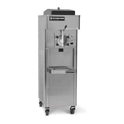
Stoelting SO218B User manual


This manual provides basic information about the machine. Instructions and suggestions are
given covering its operation and care.
The illustrations and specifications are not binding in detail. We reserve the right to make
changes to the machine without notice, and without incurring any obligation to modify or pro-
vide new parts for machines built prior to date of change.
DO NOTATTEMPT to operate the machine until instructions and safety precautions in this
manual are read completely and are thoroughly understood. If problems develop or questions
arise in connection with installation, operation, or servicing of the machine, contact Stoelting.
Stoelting Foodservice Equipment
502 Highway 67
Kiel, WI 53042-1600
U.S.A.
Main Tel: 800.558.5807
Fax: 920.894.7029
Customer Service: 888.429.5920
Fax: 800.545.0662
© 2014 PW Stoelting, LLC
stoeltingfoodservice.com

Safety Alert Symbol:
This symbol Indicates danger, warning or caution.
Attention is required in order to avoid serious per-
sonal injury. The message that follows the symbol
contains important information about safety.
Signal Word:
Signal words are distinctive words used throughout
this manual that alert the reader to the existence and
relative degree of a hazard.
CAUTION
The signal word “CAUTION” indicates a potentially
hazardous situation, which, if not avoided, may result
in minor or moderate injury and equipment/property
damage.
A Few Words About Safety
Safety Information
Read and understand the entire manual before
operating or maintaining Stoelting equipment.
This manual provides the operator with information
for the safe operation and maintenance of Stoelting
equipment. As with any machine, there are hazards
associated with their operation. For this reason safety
is emphasized throughout the manual. To highlight
specific safety information, the following safety defini-
tions are provided to assist the reader.
The purpose of safety symbols is to attract your at-
tention to possible dangers. The safety symbols, and
their explanations, deserve your careful attention
and understanding. The safety warnings do not by
themselves eliminate any danger. The instructions
or warnings they give are not substitutes for proper
accident prevention measures.
If you need to replace a part, use genuine Stoelting
parts with the correct part number or an equivalent
part. We strongly recommend that you do not use
replacement parts of inferior quality.
WARNING
The signal word “WARNING” indicates a potentially
hazardous situation, which, if not avoided, may result
in death or serious injury and equipment/property
damage.
CAUTION
The signal word “CAUTION” not preceded by the
safety alert symbol indicates a potentially hazardous
situation, which, if not avoided, may result in equip-
ment/property damage.
NOTE (or NOTICE)
The signal word “NOTICE” indicates information or
procedures that relate directly or indirectly to the
safety of personnel or equipment/property.

Section Description Page
1 Description and Specifications
1.1 Description..................................................................................................1
1.2 Specifications .............................................................................................2
2 Installation Instructions
2.1 Safety Precautions .....................................................................................5
2.2 Shipment and Transit..................................................................................5
2.3 Machine Installation....................................................................................5
3 Initial Set-Up and Operation
3.1 Operator’s Safety Precautions....................................................................7
3.2 Operating Controls and Indicators..............................................................7
3.3 Sanitizing....................................................................................................8
3.4 Freeze Down and Operation ......................................................................9
3.5 Mix Information...........................................................................................9
3.6 Removing Mix From Machine.....................................................................10
3.7 Cleaning the Machine.................................................................................10
3.8 Disassembly of Machine Parts...................................................................10
3.9 Cleaning the Machine Parts .......................................................................11
3.10 Sanitize Machine and Machine Parts.........................................................11
3.11 Assembly of Machine .................................................................................11
3.12 Routine Cleaning........................................................................................12
3.13 Preventative Maintenance..........................................................................12
3.14 Extended Storage.......................................................................................15
4 Troubleshooting
4.1 Light Indicators...........................................................................................17
4.2 Troubleshooting..........................................................................................17
5 Replacement Parts
5.1 Decals and Lubrication...............................................................................19
5.2 Auger Shaft and Faceplate Parts ...............................................................20
5.3 Hopper Parts ..............................................................................................22
5.4 Autofill Options ...........................................................................................23
TABLE OF
CONTENTS


Operators Manual #513679 Rev.1 1 SO218B Model Machine
SECTION 1
DESCRIPTION AND SPECIFICATIONS
1.1 DESCRIPTION
TheStoelting SO218Bmachineisgravityfed.Itisequipped
withfullyautomaticcontrolstoprovideauniformproduct.
Itoperateswithalmostanytypefrozenbeveragemix.This
manualisdesignedtohelpqualifiedservicepersonneland
operatorswiththeinstallation,operationandmaintenance
of the Stoelting SO218B gravity machine.
Figure 1-1 Model SO218B

Operators Manual #513679 Rev.1 2 SO218B Model Machine
Model SO218B
Dimensions Machine with crate
width 17-1/2’’ (44,5 cm) 25’’ (63,5 cm)
height 64-1/2’’ (163,8 cm) 66’’ (167,6 cm)
depth 26-3/8’’ (67,0 cm) 51’’ (129,5 cm)
Weight 315 lbs (142,8 kg) 410 lbs (185,9 kg)
Electrical 1 Phase, 208-240 VAC, 60Hz
running amps 12A
connection type NEMA6-20P power cord provided
Compressor 14,000 Btu/hr
Drive Motor 1/2 hp
Air Flow Air cooled units require 3” (7,6 cm) air space at front and back.
Plumbing Fittings Water cooled units require 3/8” N.P.T. water and drain fittings.
Hopper Volume 7 gallon (26,50 liters)
Freezing Cylinder
Volume 2 gallon (7,57 liters)

Operators Manual #513679 Rev.1 3 SO218B Model Machine
SECTION 2
INSTALLATION INSTRUCTIONS
2.1 SAFETY PRECAUTIONS
Do not attempt to operate the machine until the safety
precautionsand operating instructionsin this manualare
read completely and are thoroughly understood.
Take notice of all warning labels on the machine. The la-
bels have been put there to help maintain a safe working
environment.Thelabelshavebeendesignedtowithstand
washing and cleaning. All labels must remain legible for
thelifeofthemachine.Labelsshouldbecheckedperiodi-
callytobesuretheycanberecognizedaswarninglabels.
If danger, warning or caution labels are needed, indicate
thepartnumber,typeoflabel,locationoflabel,andquantity
required along with your address and mail to:
STOELTING
ATTENTION: Customer Service
502 Hwy. 67
Kiel, Wisconsin 53042
2.2 SHIPMENT AND TRANSIT
Themachinehasbeenassembled,operatedandinspected
at the factory. Upon arrival at the final destination, the
entire machine must be checked for any damage which
may have occurred during transit.
With the method of packaging used, the machine should
arriveinexcellentcondition.THECARRIERISRESPON-
SIBLE FOR ALL DAMAGE IN TRANSIT, WHETHER
VISIBLE OR CONCEALED. Do not pay the freight bill
until the machine has been checked for damage. Have
the carrier note any visible damage on the freight bill. If
concealeddamageand/orshortage is found later, advise
the carrier within 10 days and request inspection. The
customermustplaceclaimfordamagesand/orshortages
in shipment with the carrier. Stoelting, Inc. cannot make
any claims against the carrier.
2.3 MACHINE INSTALLATION
Installation of the machine involves moving the machine
close to its permanent location, removing all crating, set-
ting in place, assembling parts, and cleaning.
A. Uncrate the machine.
B. Accuratelevelingisnecessaryforcorrectdrainage
of machine barrel and to ensure correct overrun.
Placeabubblelevelontopofthemachineateach
corner to check for level condition. If adjustment
is necessary, level the machine by turning the
bottom part of each leg in or out.
C. Correct ventilation is required. The SO218B
requires 3” clearance at the front and back.
D. Place the CLEAN-ON-OFF switch in the OFF
position.
E. Connect the power cord to the proper power
supply.Theplugisdesignedfor208-240VAC/20
ampduty.Checkthenameplateonyourmachine
forpropersupply.Theunitmustbeconnectedtoa
properlygroundedreceptacle.Theelectricalcord
furnishedaspartofthemachinehasathreeprong
grounding type plug. The use of an extension
cord is not recommended, if necessary use one
withasize12 gauge or heavier withground wire.
Do not use an adapter to get around grounding
requirement.
CAUTION
Failure to provide adequate ventilation will void
warranty.
WARNING
Do not alter or deform electrical plug in any way.
Alteringthe plug tofit intoan outletof different con-
figuration may cause fire, risk of electrical shock,
product damage and will void warranty.
Operators Manual #513679 Rev.1 5 SO218B Model Machine
SECTION 3
INITIAL SET-UP AND OPERATION
3.1 OPERATOR’S SAFETY PRECAUTIONS
SAFE OPERATION IS NO ACCIDENT; observe these
rules:
A. Know the machine. Read and understand the
Operating Instructions.
B. Notice all warning labels on the machine.
C. Wearproperclothing.Avoidloosefittinggarments,
and remove watches, rings or jewelry that could
cause a serious accident.
D. Maintain a clean work area. Avoid accidents by
cleaning up the area and keeping it clean.
E. Stay alert at all times. Know which switch, push
button or control you are about to use and what
effect it is going to have.
F. Disconnectelectricalcordformaintenance.Never
attempt to repair or perform maintenance on the
machineuntilthemainelectricalpowerhas been
disconnected.
G. Donotoperateunderunsafeoperatingconditions.
Neveroperatethemachineifunusualorexcessive
noise or vibration occurs.
3.2 OPERATING CONTROLS AND INDICATORS
Before operating the machine, it is required that the op-
erator know the function of each operating control. Refer
to Figure 3-1 for the location of the operating controls on
the machine.
A. Spigot Switch
The spigot switch automatically starts the auger
driveandrefrigerationsystemswhenthespigotis
opened to dispense product. When the spigot is
closed,thedrivemotorandcompressorremainon
until the product in the freezing cylinder reaches
the proper consistency..
B. CLEAN-OFF-ON Switch
The CLEAN-OFF-ON switch is used to supply
powerto the controlcircuit. Whenthe switchis in
the OFF (middle) position, power is not supplied
tothecontrolboardorrefrigerationsystem.When
WARNING
High voltage will shock, burn or cause death. The
OFF-ONswitchmust be placed inthe OFF position
priorto disassembling forcleaning orservicing. Do
notoperate machine withcabinet panelsremoved.
Figure 3-1 Controls
Diagnostic
Light
Add Mix
Indicator
Clean/Off/On
Switch

Operators Manual #513679 Rev.1 6 SO218B Model Machine
the switch is in the ON position, the machine
operates in the freezing mode. When the switch
is in the CLEAN position, all refrigeration stops
and the auger starts rotating.
C. ADD MIX Light
The ADD MIX light flashes to alert the operator
to a low mix condition. It does so by monitoring
the mix level in the hopper. When the ADD MIX
light is flashing, refill hopper immediately.
NOTE
Failure to refill hopper immediately may result in
operational problems.
D. Diagnostic Light
The Diagnostic Light is on during defrost mode
and flashes if an error occurs. The light flashes
onceifthereisacompressorerror.Therearetwo
quick flashes if there is an auger error.And there
are three quick flashes if the machine is left in
clean mode for more than 20 minutes. Refer to
the troubleshooting section for details.
E. Front Door Safety Switch
The front door safety switch prevents the auger
fromturning when the frontdoorisremoved.The
switch is open when the door is not in place and
closed when the door is properly installed.
3.3 SANITIZING
Sanitizingmustbedone afterthemachineiscleanedand
justbeforethehopperisfilledwithmix.Sanitizingthenight
beforeisnoteffective.However,youshouldalwaysclean
the machine and parts after each use.
The United States Department of Agriculture and
the Food and Drug Administration require that all
cleaning and sanitizing solutions used with food
processing equipment be certified for this use.
Whensanitizingthemachine,refertolocalsanitaryregu-
lationsforapplicablecodesandrecommendedsanitizing
products and procedures. The frequency of sanitizing
must comply with local health regulations.
Mix sanitizer according to manufacturer’s instructions to
providea100partspermillion(ppm)strengthsolutionand
check the solution with chlorine test strips. Mix sanitizer
in quantities of no less than 2 gallons (7.5 liters) of 90°
to 110°F (32° to 43°C) water. Allow sanitizer to contact
the surfaces to be sanitized for 5 minutes. Any sanitizer
mustbe used only in accordancewiththemanufacturer’s
instructions.
In general, sanitizing may be conducted as follows:
A. Prepare Stera-Sheen Green Label Sanitizer
or equivalent according to manufacturer’s
instructionstoprovidea100ppmstrengthsolution.
Mix the sanitizer in quantities of no less than
2 gallons of 90° to 110°F (32° to 43°C) water.
Checkthestrengthofthesanitizingsolution.Use
a chlorine test strip and color chart to make sure
the solution has 100 ppm.Any sanitizer must be
usedonly in accordancewith themanufacturer’s
instructions.
B. Pour the sanitizing solution into the hopper and
place the switch in the CLEAN position. Check
for leaks.
C. Clean sides of hopper and underside of hopper
cover using a soft bristle brush dipped in the
sanitizing solution.
D. Afterfiveminutes,placeabucketunderthespigot
andopenspigottodrainmostsanitizingsolution.
Leave a small amount of the sanitizing solution
in the freezing cylinder. Place the switch in the
OFF (middle) position.
E. Collect the remaining sanitizing solution in a cup
andtestthechlorinecontentswithanewteststrip.
A reading of 100 ppm or more is acceptable.
If the reading is less than 100 ppm, sanitize the
machine again.
Ifthereadingislessthan100ppmaftersanitizing
the second time, disassemble and wash the
machine again.
3.4 FREEZE DOWN AND OPERATION
This section covers the recommended operating proce-
dures for the safe operation of the machine.
A. Sanitize just prior to use.
B. Place the switch in the OFF (middle) position.
C. Fill the hopper with mix.
D. Open spigot and drain a small amount of mix to
remove any remaining sanitizer.
E. Place the switch in the ON position.
NOTE
After the drive motor starts, there is a delay before
the compressor starts.
F. After 8 to 12 minutes the product will be at
consistency and ready to serve. Freeze down
time may vary depending on the type of product
used and the starting product temperature.
G. To dispense, pull the spigot handle down to open
the spigot.
CAUTION
Do not allow sanitizer to remain in contact with
stainless steel parts for prolonged periods. Pro-
longedcontactofsanitizerwithmachinemaycause
corrosion of stainless steel parts.

Operators Manual #513679 Rev.1 7 SO218B Model Machine
H. Themachineisdesignedtodispensetheproduct
at a reasonable draw rate. If the machine is
overdrawn,theresultisasoftproductoraproduct
that does not dispense at all. If this occurs, allow
themachinetorunforapproximately30 seconds
before dispensing additional product.
I. Do not operate the machine when the ADD MIX
light is on. Refill the hopper immediately.
3.5 DEFROST MODE
If the spigot has not been opened in 3 hours, defrost
mode begins. During defrost mode the drive motor runs
for 90 seconds every 7 minutes and the diagnostic light
remains lit.
Enddefrost modeby turningtheCLEAN-OFF-ON switch
OFF then back ON or by opening the spigot.
3.5 MIX INFORMATION
Mix can vary considerably from one manufacturer to an-
other.Differencesinthequantityandqualityofingredients
have a direct bearing on the finished frozen product. A
changeinmachineperformancethatcannotbeexplained
by a technical problem may be related to the mix.
Proper product serving temperature varies from one
manufacturer’s mix to another. Stackable slush mixes
generally provide satisfactory product from 24° to 28°F
(-4° to -2°C).
When checking the temperature, stir the thermometer in
the frozen product to obtain an accurate reading.
3.6 REMOVING MIX FROM MACHINE
To remove the mix from the machine, refer to the follow-
ing steps:
A. Place the switch in the CLEAN position to rotate
the auger. Allow the mix to agitate in freezing
cylinder until the mix has become liquid, about 5
minutes.
B. Drain the liquid mix by opening the spigot. A
container should be placed under the spigot to
collect the liquid mix.
C. Place the switch in the OFF (middle) position.
3.7 CLEANING THE MACHINE
NOTE
The frequency of cleaning the machine and ma-
chine parts must comply with local health regula-
tions.
After the mix has been removed from the machine, the
machine must be cleaned. To clean the machine, refer
to the following steps:
A. Closethespigot and fill thehopperwith2gallons
(8 liters) of tap water.
B. Place the switch in the CLEAN position to rotate
the auger.
C. Allow the water to agitate for approximately 30
seconds.
D. Openthespigottodrainthewater.Rememberto
place a container under the spigot to catch the
water. When the water has drained, place the
switch in the OFF (middle) position. Allow the
freezing cylinder to drain completely.
E. Prepare sanitizing solution according to
manufacturer’sinstructionstoprovidea100ppm
strength solution. Mix the sanitizer in quantities
of no less than 2 gallons of 90° to 110°F (32° to
43°C) water. Check the strength of the sanitizing
solution. Use a chlorine test strip and color chart
to make sure the solution has 100 ppm. Repeat
steps A through D using the sanitizing solution.
3.8 DISASSEMBLY OF MACHINE PARTS
Inspect for worn or broken parts each time the machine
is disassembled. Replace all worn or broken parts to
ensure safety to both the operator and the customer and
to maintain good machine performance and a quality
product. Frequency of cleaning must comply with the
local health regulations.
To disassemble the machine, refer to the following steps:
A. Remove hopper cover.
B. Pull out the spigot pin by its ring.
CAUTION
Hazardous Moving Parts.
Revolving auger shaft can grab and cause injury.
PlacetheswitchintheOFF(middle)positionbefore
disassembling for cleaning or servicing.

Operators Manual #513679 Rev.1 8 SO218B Model Machine
C. Remove the spigot handle.
D. Remove front door by turning the circular knobs
and then pulling door off the studs.
E. Remove the auger assembly from the freezing
cylinder.
F. Remove o-ring from groove in front door.
H. Remove auger support bushing.
J. Remove spigot body from the front door.
K. Removeo-rings(2)fromthespigotbyfirstwiping
off the lubricant using a clean paper towel.Then
squeezetheo-ringupwardwithadrycloth.When
a loop is formed, roll the o-ring out of the groove.
M. Remove rear seal and o-ring from auger.
N. Disassemble the rear seal assembly.
N. Remove drain tray, drip tray and drip tray grid.
3.9 CLEANING AND SANITIZING THE
MACHINE PARTS
Place all loose parts in a pan or container and take to
the wash sink for cleaning. Local and state health codes
dictatetheprocedurerequired.Somehealthcodesrequire
a four-sink process (pre-wash, wash, rinse, sanitize, and
air-dry), while other codes require a three-sink process
(without the pre-wash step). The following procedures
are a general guideline only. Consult your local and state
health codes for procedures required in your location.
A. Prepare Stera-Sheen or equivalent cleaner in
2 gallons of 90° to 110°F (32° to 43°C) water
following manufacturers instructions.
B. Prepare sanitizing solution according to
manufacturer’sinstructionstoprovidea100ppm
strength solution. Mix the sanitizer in quantities
of no less than 2 gallons of 90° to 110°F (32° to
43°C) water. Check the strength of the sanitizing
solution. Use a chlorine test strip and color chart
to make sure the solution has 100 ppm.
D. Place all parts in the cleaning solution and clean
the parts with the provided brushes. Rinse all
partswith clean90°to110°F(32°to 43°C)water.
Place the parts in the sanitizing solution.
E. Wash the hopper and freezing cylinder with the
90° to 110°F (32° to 43°C) cleaning solution and
brushes provided.

Operators Manual #513679 Rev.1 9 SO218B Model Machine
F. Clean the rear seal surfaces from the inside of
the freezing cylinder with the 90° to 110°F (32°
to 43°C) cleaning solution.
3.10 SANITIZE MACHINE
A. UseStera-Sheenorequivalentsanitizingsolution
mixed according to manufacturer’s instructions
toprovide100 parts per million strength solution.
Mixsanitizerinquantitiesofnolessthan2gallons
(7.5 liters) of 90° to 110°F (32° to 43°C) water.
Any sanitizer must be used only in accordance
with the manufacturer’s instructions.
B. With the large brush provided, sanitize the rear
of the freezing cylinder by dipping the brush in
the sanitizing solution and brushing the rear of
the cylinder.
3.11 ASSEMBLY OF MACHINE
Toassemblethemachineparts,refertothefollowingsteps:
NOTE
Petrol Gel sanitary lubricant or equivalent must be
used when lubrication of parts is specified.
NOTE
The United States Department of Agriculture and
theFoodand DrugAdministration require that lubri-
cants used on food processing equipment be certi-
fied for this use. Use lubricants only in accordance
with the manufacturer’s instructions.
A. Assemble all o-rings onto the parts dry, without
lubrication. Then apply a thin film of sanitary
lubricationtotheexposedsurfacesoftheo-rings.
Also apply a thin film of sanitary lubricant to the
inside and outside of the front auger support
bushing.
B. Assemble the rear seal adapter onto the auger
with the spring facing towards the front. Be sure
theo-ringisinplacebeforeinstallingtheassembly.
C. Assemble the o-ring into the rear seal and
assemble the seal onto the auger. DO NOT
lubricate the rear seal o-ring.
CAUTION
Do not allow sanitizer to remain in contact with
stainless steel parts for prolonged periods. Pro-
longedcontactofsanitizerwithmachinemaycause
corrosion of stainless steel parts.
Clean Rear
Seal Surface
Do Not
Lubricate
O-Ring

Operators Manual #513679 Rev.1 10 SO218B Model Machine
D. Put a small amount of spline lubricant on the hex
endoftheaugershaft.Asmallcontainerofspline
lubricant is shipped with the machine.
D. Install the plastic auger blades onto the auger.
E. Push the auger into the freezing cylinder and
rotate it slowly until the auger engages the drive
shaft.
F. Insert the spigot body into the front door.
G. Install the support bushing onto the auger.
H. Install the front door onto the machine.
I. Install the knobs on the machine studs.
J. Look for the proper seal between the freezing
cylinder, o-ring, and front door.
K. Insert the spigot handle so the hole lines up and
insert the spigot pin.
L. Install the hopper cover, drain tray, drip tray, and
drip tray grid.
The machine is assembled and ready to be sanitized.
3.12 CONSISTENCY ADJUSTMENT
The consistency adjustment screw is located behind the
right side panel near the back. Remove the black plug to
access the screw. To adjust consistency use a flat head
screwdriver.Turnclockwiseforthickerproduct and coun-
terclockwise for thinner product.Allow 15-30 minutes for
the consistency change to show up in the product.
3.13 ROUTINE CLEANING
To remove spilled or dried mix from the machine exterior,
wash in the direction of the finish with warm soapy water
and wipe dry. Do not use highly abrasive materials as
they mar the finish.

Operators Manual #513679 Rev.1 11 SO218B Model Machine
3.14 PREVENTIVE MAINTENANCE
Stoelting recommends that a maintenance schedule be
followedtokeepthemachinecleanandoperatingproperly.
A. DAILY
1. The exterior should be kept clean at all times to
preserve the luster of the stainless steel. A mild
alkalinecleanerisrecommended.Useasoftcloth
or sponge to apply the cleaner.
B. WEEKLY
1. Check o-rings and rear seal for excessive wear
and replace if necessary.
2. Remove the drip tray by gently lifting up to
disengagefromthesupportandpullingout.Clean
behindthedriptray and front of themachine with
warm soapy water.
C. QUARTERLY
Air Cooled
Theair-cooledcondenserisacoppertubeandaluminum
fin type. Condensing is totally dependent upon airflow. A
plugged condenser filter, condenser, or restrictionsin the
louveredpanel restrict airflow.Thislowersthecapacityof
the system and damages the compressor.
Thecondensermustbekeptcleanofdirtandgrease.The
machinemusthave3”(7.6cm)ventilation.Makesurethe
machine is not pulling over 100° F (37° C) air from other
equipment in the area.
Thecondenserandcondenserfilterrequireperiodicclean-
ing. To clean, refer to the following procedures.
NOTE
If the condenser is not kept clean, refrigeration ef-
ficiency is lost.
Air Cooled Condenser Cleaning
A. Slide the condenser filter out of the holding
bracket. Visually inspect it for dirt. If the filter is
dirty, shake or brush excess dirt off the filter and
wash it in warm, soapy water. Once the filter is
clean rinse thoroughly in warm, clear water and
shake dry, taking care not to damage the filter in
any way.
C. Visually inspect the condenser for dirt by shining
a light through the coil from the back (inside) of
the condenser.
D. If the condenser is dirty, place a wet towel over
the front (outside) of the condenser.
E. Using a vacuum, carefully clean the condenser
coil from the inside and outside of the machine.
Astiff bristled brush may help in releasing debris
from between the condenser coils.
Water Cooled
Thewater-cooledcondenserisatubeandshelltype.The
condenserneedsacool,cleansupplyofwatertoproperly
cool the machine. Inlet and discharge lines must be 3/8”
I.D. minimum. Make sure the machine is receiving an
unrestricted supply of cold, clean water.
E. SEMI-ANNUALLY
1. Disconnect the machine from the power source.
2. Lubricate the condenser fan motor with S.A.E.
20 weight oil. Three to six drops are required.
3.15 EXTENDED STORAGE
Refer to the following steps for storage of the machine
over any long period of shutdown time:
A. Place the CLEAN-OFF-ON switch in the OFF
(middle) position.
B. Disconnect (unplug) from the electrical supply
source.
C. Clean all parts that come in contact with mix
thoroughly with a warm water cleaning solution
Rinseincleanwateranddryparts.Donotsanitize.
NOTE
Do not let the cleaning solution stand in the hop-
per or in the freezing cylinder during the shutdown
period.
D. Remove, disassemble and clean the front door
and auger parts.
E. In a water cooled machine, disconnect the water
linesanddrainwater.Withaflatheadscrewdriver,
hold the water valve open and use compressed
air to clear the lines of any remaining water.

Operators Manual #513679 13 SO218B Model Machine
Indication On One Blink Two Blinks Three Blinks
Conditions Defrost Mode Torque is not
met after 20
minutes Drive current is not sensed Machine left in clean
mode for over 20
minutes
Self
Correction N/A N/A
The machine attempts to sense drive
current with a 3 second pre-stir. If current
is sensed, the machine returns to normal
operation. If current is not sensed, the
machine waits 7 minutes and tries to
sense current with another 3 second
pre-stir. After the third attempt, the
compressor runs on timers.
N/A
Operation Every 7 minutes
the auger runs
for 90 seconds.
Timers or until
torque switch
remains closed
for 3 seconds.
Timers Off
Corrective
Action
End Defrost
Mode by turning
Clean/Off/On
switch OFF then
turning it back
ON. Opening
the spigot also
ends Defrost
Mode.
Contact Service
Technician Contact Service Technician
Turn CLEAN-OFF-
ON switch to OFF
(middle) position then
turn the switch to ON.
SECTION 4
TROUBLESHOOTING
4.1 LIGHT INDICATORS
The machine has two lights that alert the user if a problem occurs: an ADD MIX light and a Diagnostic Light.
The ADD MIX light flashes to alert the operator to a low mix condition. It does so by monitoring the mix level in the
hopper. When the ADD MIX light is flashing, refill hopper immediately.
The Diagnostic Light flashes if an error occurs. Refer to the chart below for details.
4.2 TROUBLESHOOTING
PROBLEM POSSIBLE CAUSE REMEDY
Machine does not
run.
1 Power to machine is off. 1 Supply power to machine.
2 Blown fuse or tripped circuit. 2 Replace or reset.
3 Freeze-up (auger will not turn). 3 Turn Clean/Off/On switch Off for 15 minutes,
then restart.
4 Front door not in place. 4 Assemble front door in place.
Machine will not
shut off.
1 Drive belt failure. 1 Replace drive belt.
2 Consistency temperature setting is too
firm. 2 Turn Consistency Adjustment screw counter-
clockwise.
3 Refrigeration problem. 3 Check system. (Call distributor for service)
Product is too firm. 1 Consistency temperature setting is too
firm. 1 Turn Consistency Adjustment knob counter-
clockwise.

Operators Manual #513679 14 SO218B Model Machine
4.2 TROUBLESHOOTING - CONTINUED
PROBLEM POSSIBLE CAUSE REMEDY
Product is too thin.
1 No vent space for free flow of cooling
air. 1 A minimum of 3” of air space at the rear of the
machine
2 Condenser is dirty. 2 Clean. (See Section 3)
3 Consistency setting too soft. 3 Turn Consistency Adjustment knob clockwise.
4 Auger is assembled incorrectly. 4 Remove mix, clean, reassemble, sanitize and
freeze down.
5 Refrigeration problem. 5 Check system. (Call distributor for service)
Product does not
dispense.
1 No mix in hopper. 1 Fill hopper with mix
2 Drive motor overload tripped. 2 Wait for automatic reset. (If condition
continues, call distributor for service.)
3 Drive belt failure. 3 Replace drive belt.
4 Freeze-up (Auger will not turn). 4 Turn Clean/Off/On switch Off for 15 minutes,
then restart.
Drive belt slipping
or squealing.
1 Worn drive belt. 1 Replace drive belt.
2 Freeze-up (Auger will not turn). 2 Turn Clean/Off/On switch Off for 15 minutes,
then restart.
3 Not tensioned properly. 3 Adjust belt tension
Rear auger seal
leaks.
1 Outside surface of rear auger seal is
lubricated. 1 Clean lubricant from outside of rear seal,
lubricate inside of seal and reinstall.
2 Rear seal missing or damaged. 2 Check or replace.
3 Seal o-ring missing, damaged or
installed incorrectly. 3 Check. or replace.
4 Worn or scratched auger shaft. 4 Replace auger shaft.
Front door leaks.
1 Front door knobs are loose. 1 Tighten knobs.
2 Spigot parts are not lubricated. 2 Remove spigot and lubricate o-rings.
3 Chipped or worn spigot o-rings. 3 Replace o-rings.
4 O-rings or spigot installed wrong. 4 Remove spigot and check o-rings.
5 Inner spigot hole in front door nicked
or scratched. 5 Replace front door.
Table of contents
Other Stoelting Beverage Dispenser manuals
Popular Beverage Dispenser manuals by other brands

Continental Refrigerator
Continental Refrigerator KC50-CT Specification sheet

PEGAS
PEGAS CRAFTAP 3 Brief manual

lancer
lancer FLAVOR SELECT 22 Installation and service manual

Flavor Burst
Flavor Burst TS 44BEV user manual

Nostalgia Electrics
Nostalgia Electrics KEG7000SS instruction manual

Taylor
Taylor C302NP Operator's manual

Cornelius
Cornelius FCB - 2 Flavor Service manual

Electrolux
Electrolux BEVERAGE CENTER II Service manual

By The Glass
By The Glass Standard user manual

Narvon
Narvon 378SMM1B user manual

Vinotemp
Vinotemp VT-WINEDISP2 owner's manual

Cornelius
Cornelius Impulse Non-Carbonated Post-Mix Beverage... Installation and operation manual