STOKES VACUUM 148-10 User manual

5500 TABOR ROAD PHILADELPHIA , PA 19120
EST. 1895
M ICROVAC PUM PM ICROVAC PUM P
OPERATINGOPERATING
INSTRUCTIONSINSTRUCTIONS
Rev. 1.0Rev. 1.0
9-989-98
ISO 9 00 1ISO 9 00 1
QUALITY SYSTEMQUALITY SYSTEM
CERTIFIEDCERTIFIED
ACCREDITED BY THEACCREDITED BY THE
DUTCH COUNCILDUTCH COUNCIL
FOR CERTIFICATIONFOR CERTIFICATION
19941994
M OD EL 146 -H1 3
M ICROVAC PU M P
M OD EL 148 -H10
M ICROVAC PU M P
M OD EL 149 -H11
M ICROVAC PU M P
M OD EL 21 2 -H11
M ICROVAC PU M P
M OD EL 412 -H11
M ICROVAC PU M P
M ICROVAC PUM PM ICROVAC PUM P
OPERA TIN G INSTRUCTION SOPERATING IN STRUCTIONS
SERIA L NO. __-________SERIA L NO. __-________

STOKES VACUUM M ICROVACSTOKES VACUUM M ICROVAC
®
VACUUM PUM PVACUUM PUM P
NOTE:NOTE:
"THE INFORM ATION HEREIN SHALL BE TREATED IN THE
STRICTEST CONFIDENCE,
AND SHALL NOT BE
DISCLOSED TO ANY THIRD PARTY WITHOUT THE PRIOR
WRITTEN PERM ISSION OF
STOKES VACUUM , INC.STOKES VACUUM , INC.
THIS INFORM ATION SHALL BE USED SOLELY FOR THE
PURPOSE FOR WHICH IT HAS BEEN SUPPLIED AND FOR
NO OTHER PURPOSE
WHATSOEVER."
STOKES VACUUM , INC., PHILA DELPHIA, PASTOKES VACUUM , INC., PHILA DELPHIA, PA

STOKES VACUUM M ICROVACSTOKES VACUUM M ICROVAC
®
VACUUM PUM PVACUUM PUM P
Sect ionSect ion PagePage
1.01.0 D ESCRIPTIONDESCRIPTION
1.1 General 1-1
1.2 Gas Ballast 1-1
1.3 Water System 1-2
1.4 Electrical System 1-2
1.5 Lubricants 1-2
1.6 Guards 1-2
1.7 Vacuum Break & Gage Ports 1-2
2.02.0 IN STA LLA TIONIN STA LLA TION
2.1 Locating and Mounting 2-1
2.2 Vacuum Piping 2-1
2.3 Exhaust Piping 2-2
2.4 Electrical Connections 2-3
2.5 Cooling 2-4
2.6 Lubrication of Pump 2-4
3.03.0 OPERA TIONOPERA TION
3.1 Pre-Start Check 3-1
3.2 Pump Start 3-2
3.3 Checking Oil Level 3-2
3.4 Operation of Gas Ballast 3-2
3.5 Pump Stop 3-3
3.6 Operating Notes 3-4
4.04.0 CHECKINGCHECKIN G
4.1 Poor Vacuum 4-1
4.2 Localizing Leakage 4-1
4.3 Repairing Small Leaks 4-1
4.4 Pump Activity Record 4-2
5.05.0 TROU BLESHOOTING GUID ETROU BLESHOOTING GUID E 5-15-1
6.06.0 SPECIFICATIONS AN D PARTS LISTSPECIFICA TION S AND PA RTS LIST
7.07.0 M A IN TEN A NCEM AIN TEN A N CE
8.08.0 STOKES SU PPLEM EN TA RY D ATASTOKES SUPPLEM ENTARY DATA
Parts Ordering Information
Recommended Replacement Parts Kit
Stokes M icrovac 2-Year Warranty
Pumping Hazardous Gases Sheet
Pumping Fluids, Lubricants and Grease Bulletin

STOKES VACUUM M ICROV A CSTOKES VACUUM M ICROV A C
®
VACU U M PUM PVACU U M PUM P
BULLETINBULLETIN
CHECK YOUR M ICROVAC PUM PCHECK YOUR M ICROVAC PUM P
RESERVOIR SIGHT GLASS GAGE TO SEE IFRESERVOIR SIGHT GLASS GAGE TO SEE IF
YOUR PUM P WAS SHIPPED WITH ANYOUR PUM P WAS SHIPPED WITH AN
INITIAL CHARGE OF OIL AND/OR IF THE OILINITIAL CHARGE OF OIL AND/OR IF THE OIL
WAS SHIPPED IN SEPARATEWAS SHIPPED IN SEPARATE
CONTAINERS.CONTAINERS.
REFER TO PAGE 2-4 INITIAL FILLREFER TO PAGE 2-4 INITIAL FILL
1-11-1
STOKES VACUUM M ICROVACSTOKES VACUUM M ICROVAC® VACUUM PUM PVACUUM PUM P
SECTION 1.0
SECTION 1.0 DESCRIPTION
DESCRIPTION
1.01.0 D ESCRIPTIONDESCRIPTION
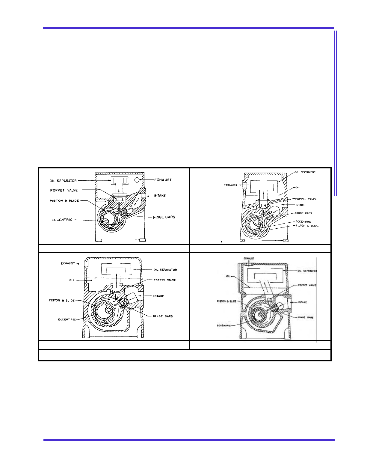
1.11 .1 GEN ERAL (Principle of Operation)GEN ERAL (Principle of Operation)
The Stokes Microvac Pump is a self-contained, rotary, oil sealed piston type unit. The piston is driven by an
eccentric mounted on the drive shaft and the piston slided is guided by tw o floating hinge bars that are free
to oscillate in the pump housing. Facing the drive end, the piston assembly rotates clockw ise. Air enters the
pump through the intake and then through the piston slide until the piston completes its stroke. At this point
all air previously entrapped is in front of the piston as it begins another stroke. As the piston continues to
rotate, the air in front of it is compressed and discharged through the exhaust valve and finally out the
exhaust outlet. As the piston nears the top center position the intake port is closed, separating the system
from the pump (See Figure 1). The exhaust valves are of the corrosion-resistant, heavy duty, poppet type.
When the pump is in operation, lubrication of the internal parts is completely automatic. Oil is forced by
atmospheric pressure from the reservoir through the oil lines to the shaft bearings. The oil is then fed into
the pump to provide the necessary piston-to-cylinder oil seal. Finally, the oil is forced out through the
exhaust valve with the air and returns to the reservoir. A solenoid valve automatically prevents oil from
flooding the pump in the event of a power failure, or when the pump is accidentally shutdown w ithout
vacuum being broken.
1.21 .2 GA S BALLA STGA S BALLA ST
The pump is provided w ith a manually operated gas ballast valve to overcome the adverse affect on vacuum
resulting from oil contamination. Contamination occurs when w ater vapor or other gaseous components
enter the pump and condense within the pump mixing with the oil as emulsified droplets. The condensate
w ill mix w ith the oil and “ flash” into vapor again as the oil circulates into high vacuum in the pump cylinder
limiting the vacuum to the vapor pressure of the condensed water. Gas Ballast is a controlled bleed of air
from the atmosphere. This air caries the w ater vapor through the compression cycle w ithout it condensing
to liquid and mixing w ith oil. Thus, the w ater vapors are exhausted without contaminating the pump oil.
Other contaminates are also removed by ballasting except those that dissolve in the oil.
FIGU RE 1 PUM P CROSS SECTIONFIGU RE 1 PUM P CROSS SECTION
M OD EL 146 -13M OD EL 146 -13 M OD EL 148 -10M OD EL 148 -10
M OD EL 1 49 -1 1 & 21 2 -11M OD EL 1 49 -1 1 & 21 2 -11 M OD EL 412 -11M OD EL 412 -11

1-21-2
STOKES VACUUM M ICROVACSTOKES VACUUM M ICROVAC® VACUUM PUM PVACUUM PUM P
SECTION 1.0
SECTION 1.0 DESCRIPTION
DESCRIPTION
NOTE:NOTE: N ever use gas ballast w hen pumping gases or gas m ixtures that are
explosive or f lam mable.
1.3 WA TER SY STEM (1 49-1 1, 2 1 2-1 1, 41 2-1 1 ON LY)1.3 WA TER SY STEM (1 49-1 1, 2 1 2-1 1, 41 2-1 1 ON LY)
A supply of cooling w ater at 85oF. and * G.P.M . maximum is needed at the water inlet for efficient perfor-
mance. See Section 2.5 for additional information.
* 149-011 1 GPM M AXIM UM
* 212-011 1-1/2 GPM M AXIM UM
* 412-011 2 GPM M AXIM UM
1.41 .4 ELECTRICAL SY STEMELECTRICAL SYSTEM
The main pow er supply is 230/460V., 60 Cy., 3 Ph. and should be wired through a suitable fused motor
starter. Pow er for the oil solenoid is taken from any tw o of the motor leads. Check both motor and sole-
noid nameplates to insure proper voltage.
1.51 .5 LU BRICA NTSLUBRICAN TS
Refer to Section 2 for recommended high vacuum grease and pumping fluids.
1.61 .6 GU ARD SGU ARD S
The standard pump is w ith a totally enclosed belt guard to cover the motor pulley, pump pulley and belts.
14 6, 14 8, 1 4 9 NOTE:146, 1 48 , 1 49 N OTE: ALSO ENCLOSED FLYWHEEL GUARDS ARE INCLUDED ASALSO ENCLOSED FLYWHEEL GUARDS ARE INCLUDED AS
STANDARD EQUIPM ENT.STANDARD EQUIPM ENT.
1.71 .7 V ACU UM BREA K & GAGE PORTSVA CU UM BREAK & GA GE PORTS
The pump is provided w ith a: 146-13 & 148-10 1/4" FPT Gage Port; 149-11,
212-11 & 412-11 l/2" FPT Vacuum Break & a l/4" FPT
Gage Port, as shown in Fig. 11.
IM PORTA N T:IM PORTA N T: When using Gage Port, provided a 9 0When using Gage Port, provided a 9 0 oo elbow and at least 1 2"elbow and at least 1 2"
of vert ical pipe t o the gage sensor.of vert ical pipe t o the gage sensor.
2-12-1
STOKES VACUUM M ICROVACSTOKES VACUUM M ICROVAC® VACUUM PUM PVACUUM PUM P
SECTION 2.0
SECTION 2.0 INSTALLATION
INSTALLATION
2.02.0 IN STA LLA TIONINSTA LLA TION
2.12 .1 LOCATING AN D M OU NTINGLOCA TIN G AN D M OUN TIN G
Locate the pump as near as possible to the equipment being evacuated so that the Vacuum, Water and
Exhaust connections can be conveniently made. Provide for adequate space for convenient servicing where
possible.
2.1.2 The pump should be mounted on a rigid foundation, such as a concrete floor, and made level by
shimming or grouting, if necessary. Bolt pump to foundation without putting a strain or tw ist in the pump
housing. See Figure 12 for foundation bolting dimensions.
2.1.3 Remove cap from exhaust and intake openings only w hen ready to make a pipe connection. Also
remove the plastic plug (by unscrew ing) from the Gas Ballast valve. When pump is to be subjected to
temperatures below freezing, drain w ater jacket through the housing drain plug to prevent cracking the
housing, then blow out w ater jacket. Follow this same procedure for storage.
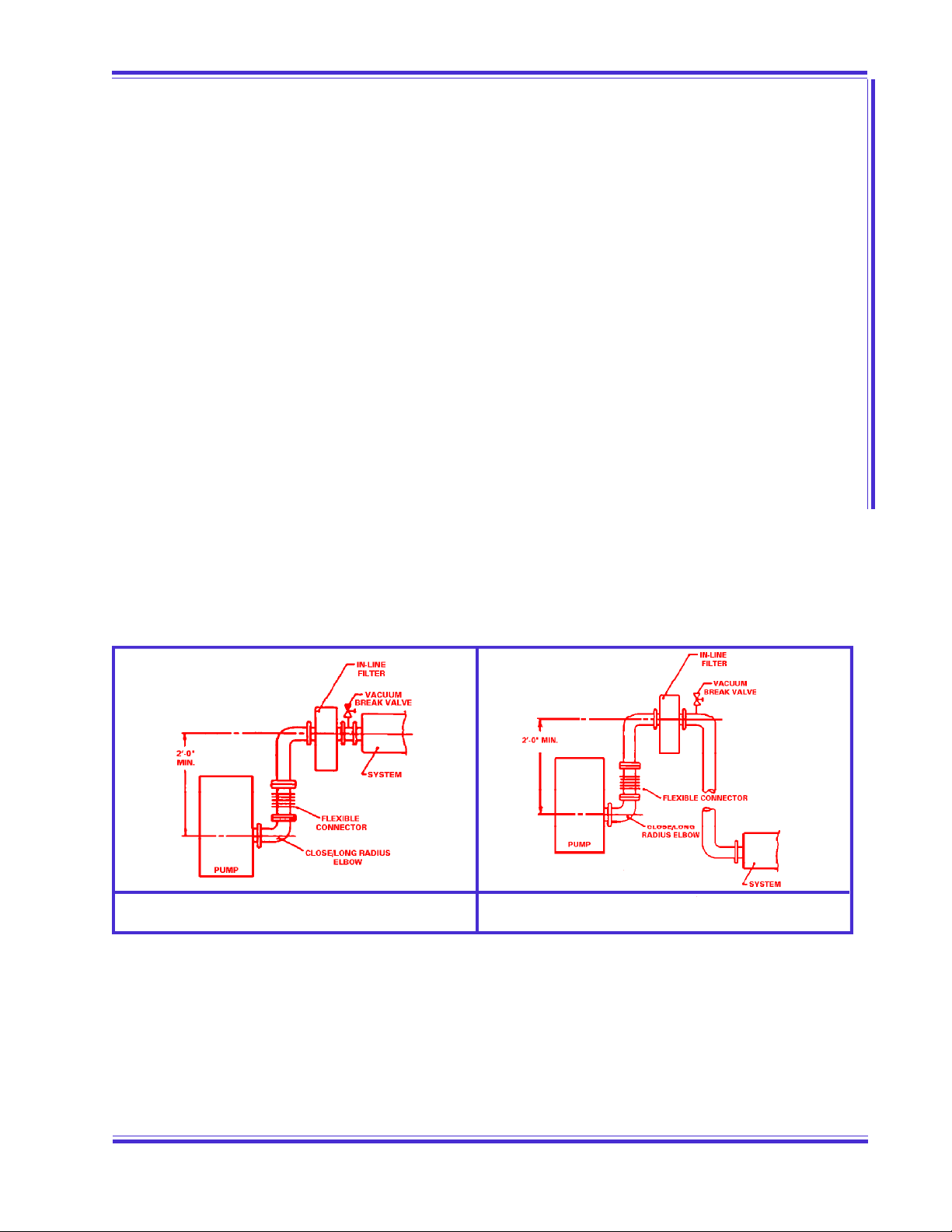
2.22 .2 V ACU UM PIPIN GVA CU UM PIPIN G
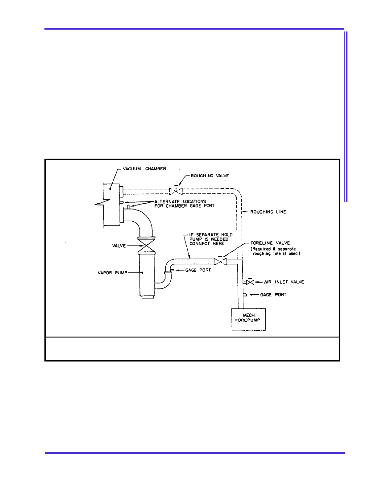
Be sure all vacuum piping is tight.Be sure all vacuum piping is tight. All pipe lines should be as short as possible and should be no smaller
than the inlet to the pump. (If it is absolutely necessary to run a long line, the pipe size should be increased
50% in diameter, or more, than the inlet to the pump.) Conductance of long lines must be checked and the
line sized large enough or pumping speed of system w ill be seriously decreased. When connecting pump to
the system, provide a vertical pipe at least 2 ft. long betw een the pump and the system, if the pump is
below the system inlet. If the pump is above or level w ith the system inlet, provide an inverted “ U” pipe to
serve as a trap for dirt from the system and to prevent migration of pump oil tow ard the system inlet. Be
sure all vacuum piping is tight. If an inline filter is being used it should be installed as noted below . It is
advisable to install a flexible connection betw een pump intake and vacuum piping to eliminate vibration.
(See Figures 2 &3).
A high vacuum valve (full opening type preferred) is recommended to facilitate start-up and for checking
pump blank off pressure.
CA U TION:CA U TION: M ak e sure t he syst em t o be evacuated and connect ing lines areM ake sure the syst em t o be evacuated and connect ing lines are
clean and f ree of w eld splat ter, dirt, or grit . Foreign mat terclean and f ree of w eld splat ter, dirt, or grit . Foreign mat ter
ent ering t he pum p can cause f ailure and possibly damage theent ering t he pum p can cause f ailure and possibly damage the
int ernal parts. To prevent this it is recom mended that a 1 6 meshint ernal parts. To prevent this it is recom mended that a 1 6 mesh
w ire screen be inst alled at the inlet connection. Af ter 20 hours ofw ire screen be inst alled at the inlet connection. Af ter 20 hours of
operat ion t he screen m ust be rem oved.operat ion t he screen m ust be rem oved.
FIGU RE 2FIGU RE 2
PU M P BELOW SYSTEMPU M P BELOW SYSTEM
FIGU RE 3FIGU RE 3
PU M P ABOV E SYSTEMPUM P A BOV E SY STEM
2-22-2
STOKES VACUUM M ICROVACSTOKES VACUUM M ICROVAC® VACUUM PUM PVACUUM PUM P
SECTION 2.0
SECTION 2.0 INSTALLATION
INSTALLATION
2.2.12.2.1 TYPES OF PIPING JOINTSTYPES OF PIPING JOINTS
A. Standard w rought piping with w elded joints makes the best vacuum piping system.
B. Copper piping w ith sw eated fittings and joints can also be made vacuum tight and has the
advantage of providing a neat, clean vacuum installation.
C. Standard threaded piping, how ever, is satisfactory and more readily installed. The piping
should be carefully hammered to loosen any scales or chips. Blow out the resultant w ith
compressed air prior to installation. All male threaded joints should be carefully doped,
screw ed up tight and NEVER “ backed-off” to make parts align - this is apt to cause a leak.
Paint the joints w hile the system is under vacuum until the paint is no longer drawn in, G.E.
1201-B, Glyptal or equivalent is recommended for painting all connections.
2.2.22.2.2 LOCATION OF GAGE PORTLOCATION OF GAGE PORT
A vacuum gage connection is located at the upper left hand side of intake side of pump. (See Figure
12). The pipe plug found at this location should be replaced with a small vacuum ball valve to w hich
the gage can be connected. When a Stokes McLeod Gage is used a synthetic, thick w all, smooth
bore tubing, such as Tygon, makes a very satisfactory flexible connection.
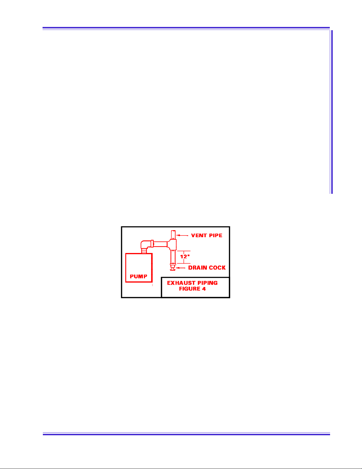
2.32 .3 EX HA UST PIPIN GEX HA UST PIPIN G
2.3.1 It is recommended that the exhaust be piped horizontally as short distance and tied into a vertical
exhaust pipe. The vertical exhaust pipe must be at least 1 ft. (12 inches) long and the bottom end of the
vertical exhaust pipe terminated w ith a plug or a drain cock to allow removal of moisture and contaminated
oil before it can accumulate sufficiently to drain back into pump oil reservoir. See Figure 4.
2.3.2 The exhaust pipe should be no smaller than the exhaust outlet and as short as possible. Run the
pipe outside the building w here the pump exhaust vapors w ill not be objectionable. Point the outside end of
the exhaust pipe downw ard to prevent the entrance of rain water.
2.3.3 Closed circuit Oil M ist Separators are available from Stokes which can eliminate oil fog in the
majority of applications. The separator will not remove noxious or toxic gases and must be run outside the
building. For operating continually under conditions of higher pressure an electro-static precipitator is
recommended. Contact Stokes for specifics.
CA U TION:CA U TION: NEVER PLACE A V ALV E IN THE EX HAU ST LIN E. IF A VALV ENEV ER PLA CE A VA LVE IN THE EX HA U ST LINE. IF A V ALV E
M UST BE INSTA LLED IN THE LIN E, A RELIEF V ALV E M U ST A LSOM UST BE INSTA LLED IN THE LIN E, A RELIEF V ALV E M U ST A LSO
BE IN SERTED IN THE LIN E BETWEEN THE RESERVOIR AN D THEBE IN SERTED IN THE LIN E BETWEEN THE RESERVOIR AN D THE
VA LVE. THE RELIEF VA LVE SHOULD BE EQU AL IN SIZE TO THEVA LVE. THE RELIEF VA LVE SHOULD BE EQU AL IN SIZE TO THE
LIN E, AN D SET TO OPEN A T 2 PSIG.LIN E, AN D SET TO OPEN A T 2 PSIG.

2-32-3
STOKES VACUUM M ICROVACSTOKES VACUUM M ICROVAC® VACUUM PUM PVACUUM PUM P
SECTION 2.0
SECTION 2.0 INSTALLATION
INSTALLATION
2.42 .4 ELECTRICAL CONN ECTIONS (See Figure 5)ELECTRICAL CONN ECTIONS (See Figure 5 )
CA U TION:CA U TION: BE SURE PU M P IS PROPERLY LU BRICA TED BEFORE STARTING.BE SU RE PUM P IS PROPERLY LUBRICATED BEFORE STARTING.
2.4.1 Install a motor starter w ith safety device within easy reach of the operator.
2.4.2 Connect the solenoid valve as in Figure 5.
2.4.3 Connect motor so that pump shaft rotates clockwise w hen view ed from driven end. See 3.1 for
Pre-Start Check.
NOTE:NOTE: M AKE SU RE THE PROPER VOLTAGE, STA RTERS AN D OV ERLOA DSM AKE SURE THE PROPER V OLTA GE, STA RTERS AN D OVERLOA DS
ARE SUPPLIED TO THE M OTOR. M AKE SU RE THA T THE SOLENOIDARE SUPPLIED TO THE M OTOR. M AKE SU RE THA T THE SOLENOID
COIL LEAD S ARE CONN ECTED FOR PROPER V OLTA GE. BOTH M AYCOIL LEAD S ARE CONN ECTED FOR PROPER V OLTA GE. BOTH M AY
FAIL TO OPERA TE IF V OLTA GE IS LESS THA N 90 % OF RATED .FAIL TO OPERA TE IF V OLTA GE IS LESS THA N 90 % OF RATED .
FIGU RE 5FIGU RE 5
WIRIN G D IAGRAMWIRIN G D IAGRAM

2-42-4
STOKES VACUUM M ICROVACSTOKES VACUUM M ICROVAC® VACUUM PUM PVACUUM PUM P
SECTION 2.0
SECTION 2.0 INSTALLATION
INSTALLATION
2.52 .5 COOLIN GCOOLIN G
FOR PUM P M ODELS 146-13 AND 148 -10 USE 2.5.1 THAT FOLLOWS. F0R 149-11, 212-11, AND 412-11FOR PUM P M ODELS 146-13 AND 148 -10 USE 2.5.1 THAT FOLLOWS. F0R 149-11, 212-11, AND 412-11
USE 2.5.1 THRU 2.5.5.USE 2.5.1 THRU 2.5.5.
2.5.1 This pump is air cooled and no w ater connections are necessary.
149-11, 212-11 & 412-11ONLY149-11, 212-11 & 412-11ONLY
2.5.1 This pump is w ater cooled and must be connected to a w ater supply.
2.5.2 The 1/2" w ater inlet connection is located in the pump housing on the drive side near the bottom.
2.5.3 Insert a valve in the w ater inlet line and regulate the water flow so that the temperature of the oil in
the reservoir is betw een 140 Deg. and 160 Deg. F. Oil temperature kits are available that automatically
control the w ater flow to maintain the proper oil temperature (Consult factory). If pump is outside and
subjected to freezing temperatures, w ater tank and circulating pump should be installed with anti-freeze in
the w ater.
CA U TION:CA U TION: DO NOT STA RT PU M P WHEN OIL TEM PERATU RE IS BELOW 5 5DO N OT START PU M P WHEN OIL TEM PERATU RE IS BELOW 5 5 oo F.F.
2.5.4 The 1/2" w ater outlet is located in the pump housing on the opposite side of the w ater inlet.
2.5.5 The w ater outlet SHOULDSHOULD be connected to an open drain to permit the operator to check the flow
and temperature of the outlet water periodically. There SHOULD NOTSHOULD NOT be a valve or back pressure in this
line. In some cases, cooling w ater must be discharged to a pressure drain. In such cases, discharge
pressure must not exceed 50 P.S.I.G. and no block valve should be placed in discharge line unless a 50#
relief valve is provided to protect pump from high inlet pressure.
NOTE:NOTE: IF COND ENSA BLES A RE PRESEN T IN GAS BEING PU M PED AN DIF COND EN SA BLES A RE PRESEN T IN GAS BEING PU M PED AND
GA S BALLA ST IS USED THROTTLE THE COOLING WA TER TO RA ISEGA S BALLA ST IS U SED THROTTLE THE COOLIN G WA TER TO RAISE
OPERA TIN G TEM PERA TU RE TO THE LEV EL N EEDED FOR GA SOPERA TIN G TEM PERA TU RE TO THE LEV EL N EEDED FOR GA S
BALLA ST (SEE SECT. 3 ).BALLA ST (SEE SECT. 3 ).
2.62 .6 LU BRICA TION OF PUM PLUBRICATION OF PU M P
The successful operation of this pump depends largely on the type of oil used. An initial charge of oil is
included w ith each pump. This standard oil is V-Lube (Label F) which is recommended for general operating
conditions in a relatively clean environment. The oil is a multigrade petroleum oil, fortified for oxidation
protection, containing detergent dispersants, w ith excellent flow characteristics at low temperature. It has
a viscosity of 430 SSU at 100 Deg. F., and 82 SSU at 210 Deg. F., with a vapor pressure of 0.0001 mm Hg.
at 145 Deg. F.
If the pump is to be operated at vacuum levels that cause the oil temperature to exceed 160 Deg. F. for
extended periods of time, a heavier grade oil should be used, Stokes V-lube (Label G) is available for oil
temperatures up to 200 Deg. F.
Special operating conditions may require the use of Special oils. We have listed the most used special
lubricants on the back page of the Bulletin enclosed, Greasing and Pumping Fluids for Vacuum Components.
Consult Stokes for specific recommendations when other than regular petroleum oils are being used.
2.6.12.6.1 INITIAL FILLINITIAL FILL
The microvac pump is shipped w ith an Initial charge of oil (* gallons) in the reservoir. Before connecting the
suction manifold slow ly rotate the pump thru tw o revolutions. This will distribute the oil throughout the
pump interior.

2-52-5
STOKES VACUUM M ICROVACSTOKES VACUUM M ICROVAC® VACUUM PUM PVACUUM PUM P
SECTION 2.0
SECTION 2.0 INSTALLATION
INSTALLATION
146-13 2 QUARTS
148-10 1-1/2 GALLONS
149-11 2-1/2 GALLONS
212-11 4 GALLONS
412-11 12 GALLONS
NOTE:NOTE: STARTING THE M ICROVA C PU M P WHEN OIL TEM PERA TU RE ISSTA RTIN G THE M ICROV A C PUM P WHEN OIL TEM PERA TURE IS
BELOW 5 5 D EG. F., CAN RESULT IN EX CESSIVE WEAR AN DBELOW 5 5 D EG. F., CAN RESULT IN EX CESSIVE WEAR AN D
GA LLIN G DAM A GE TO THE M OVIN G PA RTS.GA LLIN G DAM A GE TO THE M OVIN G PA RTS.

3-13-1
STOKES VACUUM M ICROVACSTOKES VACUUM M ICROVAC® VACUUM PUM PVACUUM PUM P
SECTION 3.0
SECTION 3.0 OPERATION
OPERATION
3.03.0 OPERA TIONOPERATION
3.13 .1 PRE-START CHECKPRE-START CHECK
NOTE:NOTE: REM OV E BELT GU ARD COV ER. TURN PUM P OV ER BY HA ND A TREM OV E BELT GU ARD COV ER. TURN PUM P OV ER BY HA ND AT
LEAST TWO REVOLU TIONS.LEAST TWO REVOLU TIONS.
A. Jog the motor momentarily w hile observing pump rotation. If the pump does not rotate in a
clockwise direction, interchange any tw o of the three-phase leads.
B. M ake sure the oil solenoid valve operates properly by checking the oil flow indicator. The
ball in the Oil Flow Indicator bowl should rise after system pressure is below 600 mm Hg.
(6" Hg. Suction).
C. The oil solenoid valve is normally closed, and must be energized when the pump starts.
The differential pressure betw een the oil reservoir (atmospheric pressure) and the pump
cavity (vacuum) forces the oil to the bearings and into the pump cavity. The oil lubricates
the moving parts and also creates an oil seal.
Oil starts to flow at 600 Torr. At 400 Torr the flow is approximately 50% . From 100% Torr
to blank-off (15u), flow is 100% .
NOTE:NOTE: Y OU M UST REACH 400 TORR IN 10 M INUTES OR A FORCEYOU M UST REA CH 400 TORR IN 10 M INUTES OR A FORCE
FEED LUBRICA TION SYSTEM IS REQU IRED TO PROV ID EFEED LUBRICA TION SYSTEM IS REQU IRED TO PROV ID E
ADEQUATE OIL FLOW TO THE PU M P CAVITY.ADEQUATE OIL FLOW TO THE PU M P CAVITY.
NOTE:NOTE: IF IN DICATOR BA LL DOES N OT RISE, STOP PUM P IM M ED IA TELY.IF INDICA TOR BALL D OES NOT RISE, STOP PU M P IM M EDIATELY .
(1) CHECK OPERA TION OF SOLENOID. (2) CHECK OIL LIN ES FOR(1) CHECK OPERA TION OF SOLENOID. (2) CHECK OIL LIN ES FOR
BLOCKAGEBLOCKAGE
3.1.23.1.2 DRIVE BELT TENSIONDRIVE BELT TENSION
A. At approximately the center of the span, betw een drive and driven pulleys, apply * pounds
pressure on the belt. If tension is correct, the resulting deflection should be * * .
M ODEL * LBS. * * DEFLECTION
146-13 1 TO 2 1/2"
148-10 3 TO 5 5/16 TO 3/8"
149-11 2 TO 3 7/16"
212-11 3 TO 5 7/16"
412-11 5 TO 7 1/2"
B. Adjust, if necessary, by raising or low ering the location nuts on the motor support eyebolt.
Tighten these nuts securely after adjustments.
NOTE:NOTE: M AINTEN AN CE OF PROPER BELT TEN SION IS IM PORTAN T. TOOM AIN TEN ANCE OF PROPER BELT TENSION IS IM PORTA NT. TOO
TIGHT A NY AD JUSTM ENT IS HA RM FUL TO THE SHA FT BEARINGS.TIGHT A NY AD JUSTM ENT IS HA RM FUL TO THE SHA FT BEARINGS.
TOO LOOSE A N AD JU STM ENT A LLOWS THE BELT TO SLIP.TOO LOOSE A N AD JU STM ENT A LLOWS THE BELT TO SLIP.

3-23-2
STOKES VACUUM M ICROVACSTOKES VACUUM M ICROVAC® VACUUM PUM PVACUUM PUM P
SECTION 3.0
SECTION 3.0 OPERATION
OPERATION
3.23 .2 PU M P STA RTPU M P STA RT
3.2 .1 f or 14 9 -11 , 2 12-1 1 & 41 2 -11 ON LY3.2 .1 f or 14 9 -11 , 2 12-1 1 & 41 2 -11 ON LY, Turn cooling w ater ONON..
CA U TION:CA U TION: DO NOT STA RT PU M P WHEN OIL TEM PERATU RE IS BELOW 5 5DO N OT START PU M P WHEN OIL TEM PERATU RE IS BELOW 5 5 oo F.F.
NOTE:NOTE: REM OV E PLA STIC PLU G FROM EX HAUST PORT BEFOREREM OV E PLA STIC PLUG FROM EX HA UST PORT BEFORE
OPERA TIN G PU M POPERA TIN G PU M P
3.2.1 Depress “ start” button and check solenoid valve for proper operation.
3.2.2 Be sure the equipment being evacuated is properly cleaned and all openings closed. Open intake
valve.
3.33 .3 CHECKIN G OIL LEV ELCHECKIN G OIL LEV EL
3.3.1 Check oil level each day.
3.3.2 The oil level should be at center of sight glass or in low er half w hile pump is operating at high
vacuum. Level will change depending on suction pressure. In most cases, oil is added after
operating the pump for a short w hile.
3.3.3 To avoid blow ing oil out the fill hole, do not add oil to the pump w hen in operation unless the pump
is at 1 torr or less w ithout Gas Ballast.
NOTE:NOTE: When pum ping gases t hat cont ain w at er vapor it may be necessaryWhen pum ping gases t hat contain w at er vapor it may be necessary
to remove the w ater t hat condenses in the pump reservoir sum p.to remove the w ater t hat condenses in the pump reservoir sum p.
This can be done by opening the oil drain valve and draining outThis can be done by opening the oil drain valve and draining out
w ater, and closing valve w hen oil starts t o flow . The int erval f orw ater, and closing valve w hen oil starts t o flow . The int erval f or
this must be det erm ined for each specif ic operation and depends onthis must be det erm ined for each specif ic operation and depends on
the amount of w ater vapor and oil t em perature. Operating t hethe amount of w ater vapor and oil t em perature. Operating t he
pum p w ith t he oil t em perature in the 1 60 Deg. F., t emperat urepum p w ith t he oil t em perature in the 1 60 Deg. F., t emperat ure
range w ill tend to minim ize f orm at ion of w ater, but w ill notrange w ill tend to minim ize f orm at ion of w ater, but w ill not
eliminat e it.elim inate it .
3.43 .4 OPERATION OF GA S BA LLASTOPERA TION OF GA S BA LLAST
3.4.1 Open the Gas Ballast valve fully for maximum efficiency. For a lesser degree of ballasting, turn
valve tow ard close position. Full gas ballast w ill cause pump temperature to rise but this is normal.
For maximum effect of gas ballast, pump should be run approximately at l60 Deg. F.
149-11, 212-11, & 412-11ONLY149-11, 212-11, & 412-11ONLY Operating temperature can be raised by throttling cooling water. Oil
Temperature Control Kits are available, consult factory.
NOTE:NOTE: Be sure to remove the plast ic plug in the Gas Ballast air int ak eBe sure to remove the plast ic plug in the Gas Ballast air intake
lines. This plug is used f or shipping and storage purposes ON LYlines. This plug is used f or shipping and storage purposes ON LY
3.4.2 If pumping water vapor in excessive quantities and the oil has become contaminated, it can be
purified by running the pump w ith Gas Ballast valve full open while the pump is shut-off from the
system. When excessive contaminants are present, indicated by high oil level, or thinning,
formation of varnish, etc., the oil should be replaced.
3-33-3
STOKES VACUUM M ICROVACSTOKES VACUUM M ICROVAC® VACUUM PUM PVACUUM PUM P
SECTION 3.0
SECTION 3.0 OPERATION
OPERATION
CA U TION:CA U TION: Gas Ballast should never be used if vapors being pum ped areGas Ballast should never be used if vapors being pumped are
explosive, e.g. M ethane Gas, Hydrogen, and certain solvent vapors.explosive, e.g. M ethane Gas, Hydrogen, and certain solvent vapors.
When gases of an explosive nature are being handled, the safestWhen gases of an explosive nat ure are being handled, the saf est
procedure is t o rem ove t he gas ballast valve ent irely and plug orprocedure is t o rem ove the gas ballast valve entirely and plug or
cap t he pipe to w hich t he gas ballast valve is at tached.cap t he pipe to w hich t he gas ballast valve is at tached.
Opening the gas ballast slightly w ill quiet valve noise when pump is blanked-off, but w ill prevent
reaching the low est final pressure.
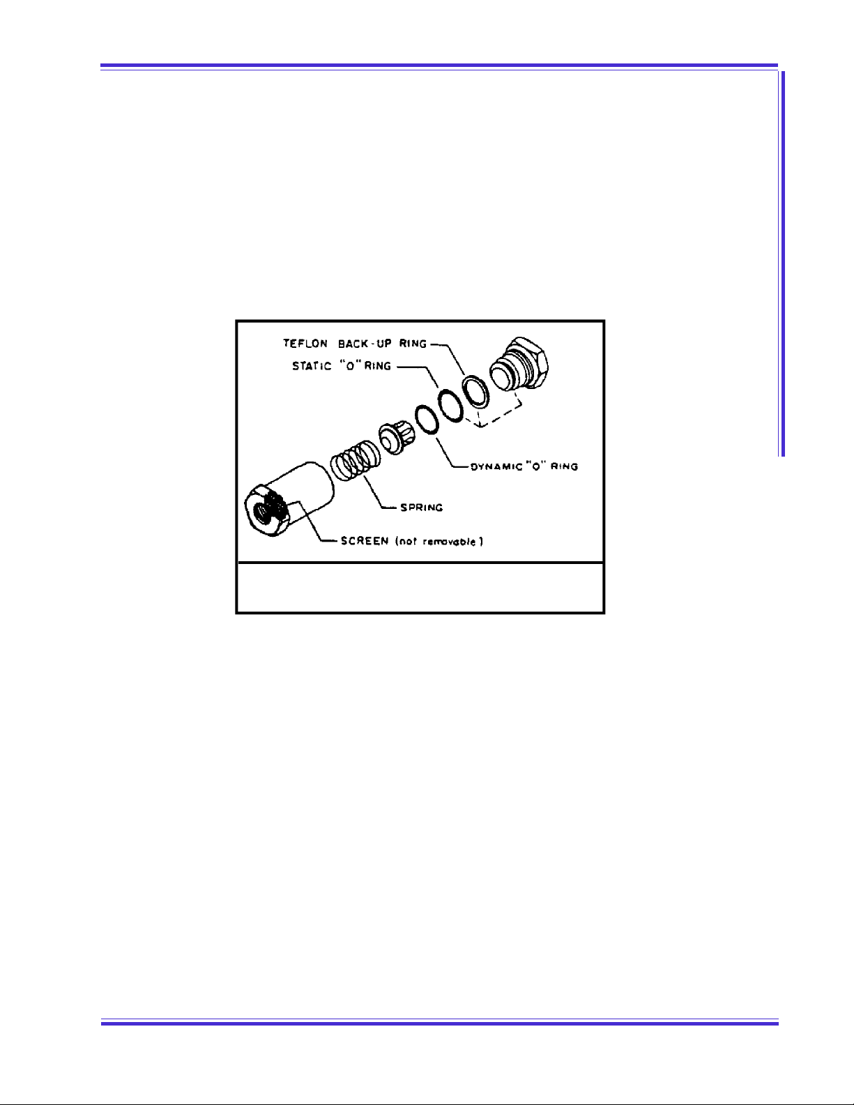
3.4.3 The check valve used for Gas Ballast should be inspected at least every six months for w ear or a
broken spring w hen operating on an (8) hour a day basis; every 3 months for (24) hour a day
operation.
3.4.4 The gas ballast valve should be closed w hen the pump is stopped. If the valve is open, gas will be
sucked into the pump through the valve and the vacuum manifold will be pressurized w ith
atmospheric air. This air going through the pump w ill carry the oil in the pump cylinder system. A
solenoid valve attached to the gas ballast piping can be used to operate the gas ballast
automatically. Contact local Stokes representative for additional information.
3.4.5 When a pressurized gas is used to ballast the pump, the pressure must be reduced to 2 psi
maximum. The use of higher pressures may damage the pump.
3.4.6 When pumping an explosive gas, (i.e. hydrogen, silane, methane) or corrosive gas, (cl, f, ccl4, etc.)
the pump must be ballasted w ith an inert gas (nitrogen, argon). The used of air for ballasting under
the above conditions can result in an explosion or excessive corrosion inside the pump.
3.53 .5 PU M P STOPPU M P STOP
3.5.1 Close intake valve to system.
3.5.2 Stop the motor and break vacuum unless system dictates otherwise.
FIGU RE 6FIGU RE 6
GA S BA LLA ST CHECK V ALVEGA S BA LLA ST CHECK V ALVE

3-43-4
STOKES VACUUM M ICROVACSTOKES VACUUM M ICROVAC® VACUUM PUM PVACUUM PUM P
SECTION 3.0
SECTION 3.0 OPERATION
OPERATION
NOTE:NOTE: The solenoid valve closes aut omat ically w hen the pump is stoppedThe solenoid valve closes aut omatically w hen the pump is stopped
or in case of pow er f ailure, thus prevent ing pum p and vacuumor in case of pow er f ailure, thus prevent ing pum p and vacuum
syst em from being flooded w it h oil.syst em from being flooded w it h oil.
3.63 .6 OPERATING NOTESOPERA TIN G NOTES
3.6.1 If large amounts of air pass through the pump, it may become w arm and under severe conditions
may become hot. This does not indicate trouble. The pump is designated for high vacuum w ork
and should not be operated at pressures above 600 mm Hg. for more than 15 minutes or at
intermediate vacuums for periods w hich cause oil temperature to exceed 200 Deg. F. For optimum
pump operation the oil temperature of the oil in the reservoir should be betw een 140 Deg. F. and
160 Deg. F. w ith the pump operating on the system or process. Oil temperature can be measured
by inserting a thermometer in the fill hole or by contact pyrometer on oil line near the solenoid. If
the pump is to be operated with oil temperature in excess of 160 Deg. F. the use of a heavier
viscosity oil is recommended. (See Section 2.6.)
3.6.2 When starting the pump or when handling large amounts of air, oil vapor in the form of smoke w ill
issue from the exhaust. Again this is no indication of trouble, as the volume of smoke w ill decrease
as the vacuum in the system improves.
NOTE:NOTE: St ok es closed type oil m ist separat or is available to alleviat eSt okes closed t ype oil mist separator is available t o alleviate
exhaust oil sm og.exhaust oil sm og.
3.6.3 If the pump has been shut dow n for an extended period, alw ays turn over at least tw o (2)
revolutions by hand before starting to insure free movement of parts.
3.6.4 Low oil temperature can cause overloading w hen starting the pump and possibly prevent the pump
from sealing. M icrovac pumps should not be started w hen the oil temperature is below 55 Deg. F.*
Optimum operating oil temperature after starting is betw een 140 Deg. F. to 160 Deg. F. Opening
the Gas Ballast valve will help w arm-up the oil.
A Water M iser is recommended to automatically control the oil temperature.
* THIS APPLIES ON LY IF STOKES V-LUBE “ F” IS USED. CONSU LT FACTORY IF OTHER* THIS APPLIES ON LY IF STOKES V-LUBE “ F” IS USED. CONSU LT FACTORY IF OTHER
OILS ARE USED.OILS A RE U SED .
4-14-1
STOKES VACUUM M ICROVACSTOKES VACUUM M ICROVAC® VACUUM PUM PVACUUM PUM P
SECTION 4.0
SECTION 4.0 CHECKING
CHECKING
4.04.0 CHECKINGCHECKING
4.14 .1 POOR VA CU UMPOOR V ACU UM
No pump w ill give good results on a poor vacuum system. If the vacuum in the system is unsatisfactory,
the usual cause is leakage. To check for this condition, a methodical approach w ill usually resolve the
problem in the least amount of time.
4.24 .2 LOCALIZING LEA KA GELOCALIZING LEA KA GE
A leak rate w ill help localize a vacuum leak. Such a test is easily made by successively isolating and evacu-
ating each section of the system. The in-leakage rate of the isolated section is then noted.
4.2.1 A vacuum leak detector w ill speed up the process of the locating leaks.
4.34 .3 REPAIRING SM ALL LEA KSREPA IRIN G SM A LL LEAKS
To repair small leaks or to close pores, use Sealing Compound, Stokes Part No. 4-927. When replacing plug
type valves (if used) use Locktite Pipe Sealer No. 7l4-l to help seal them. Gate, Ball or Butterfly type high
vacuum valves are preferred for high vacuum service.
NOTE:NOTE: U se of Teflon Tape f or sealing is not recom mended. M aterial isUse of Teflon Tape f or sealing is not recom mended. M aterial is
of ten draw n into system , causing prem at ure w ear and dam age t oof ten draw n into system , causing prem at ure w ear and dam age t o
moving part s.moving part s.
FIGU RE 7FIGU RE 7
STAND A RD VACU U M SY STEM PIPINGSTAND A RD VACU U M SY STEM PIPING

4-24-2
STOKES VACUUM M ICROVACSTOKES VACUUM M ICROVAC® VACUUM PUM PVACUUM PUM P
SECTION 4.0
SECTION 4.0 CHECKING
CHECKING
4.44.4 PU M P ACTIVITY RECORDPUM P A CTIV ITY RECORD
A record of oil changes, work done on pump, and changes or additions to the system will be of value in
checking for leaks or poor vacuum.
NOTE:NOTE: A sample mechanical vacuum pum p prevent ive m aintenance checkA sam ple m echanical vacuum pump preventive maint enance check
list along w ith a sum mary of major at tention items is enclosed forlist along w ith a sum mary of major at tention items is enclosed for
your review .your review .

5-15-1
STOKES VACUUM M ICROVACSTOKES VACUUM M ICROVAC® VACUUM PUM PVACUUM PUM P
SECTION 5.0
SECTION 5.0 TROUBLESHOOTING GUIDE
TROUBLESHOOTING GUIDE
5.05.0 TROU BLESHOOTING GUID ETROU BLESHOOTING GUID E
VA CU UM AT PUM P ISVA CU UM A T PUM P IS
UN SA TISFACTORYUN SA TISFACTORY
PROBABLE CA U SE POSSIBLE REM EDY
A. CONTAM INATED OR INSUFFICIENT OIL. 1. CHECK OIL LEVEL; UTILIZE GAS
BALLAST.
2. DRAIN AND WIPE OUT RESERVOIR AND
VALVE CHAM BER. REFILL WITH
PROPER OIL.
B. SOLENOID OIL VALVE NOT OPERATING
PROPERLY OR INOPERATIVE.
CHECK AND, IF NECESSARY CLEAN AND
OR REPLACE SOLENOID VALVE OR COIL.
C. LOOSE INTAKE FLANGE OR COVER
BOLTS.
TIGHTEN FALNGE AND SIDE COVER
BOLTS AT REGULAR INTERVALS.
D. OIL M ANIFOLD OR INTERGRAL OIL
DISTRIBUTION LEAKING.
TIGHTEN PLUGS AND M ANIFOLD
SCREWS.
E. OIL LEVEL SIGHT GLASS LEAKING CAREFULLY TIGHTEN SCREWS
F. EXHAUST VALVE NOT SEALING 1. DISASSEMBLE, CLEAN AND CHECK ALL
PARTS THOROUGHLY.
2. REPLACE ANY DAM AGED OR WORN
PARTS.
G. PUM P SEIZES OR KNOCKS
EXCESSIVELY; INTERNAL PARTS BADLY
WORN OR BROKEN
DISASSEM BLE PISTON ASSEM BLY.
REPLACE WORN, BROKEN OR BADLY
SCORED PARTS.
H. LEAKAGE IN VACUUM SYSTEM CHECK SYSTEM AS DESCRIBED IN
SECTION 4.0.
VA CU UM PU M P EX CESSIV ELYVA CU UM PU M P EX CESSIV ELY
NOISYNOISY
PROBABLE CA U SE POSSIBLE REM EDY
A. PUM P KNOCKING 1. CHECK OIL LEVEL, AND OIL SOLENOID
VALVE FOR PROPER OPERATION.
2. BROKEN PARTS OR FOREIGN M ATERIAL
IN THE PUM P.
3. DISASSEM BLE AND REM OVE FOREIGN
M ATERIAL IN THE PUM P.
4. REPLACE BROKEN PARTS AS
REQUIRED.
B. PUM P SEIZES DUE TO LACK OF
LUBRICATION, OR PRESENCE OF
FOREIGN M ATERIAL.
1. CHECK SOLENOID VALVE FOR PROPER
OPERATION.
2. DISASSEM BLE AND REM OVE FOREIGN
M ATERIAL. M AKE SURE OIL LINES ARE
NOT CLOGGED.
3. SM OOTH M INOR SCORING WITH #500
EM ERY CLOTH AND WASH
THOROUGHLY THEN OIL BEFORE
INSTALLING. (A CERTAIN AM OUNT OF
SCORING TO THE PISTON AND
CYLINDER AND OTHER PARTS USUALLY
WILL NOT SERIOUSLY AFFECT THE
VACUUM OBTAINABLE SO LONG AS
SCORING IS NOT IN A CONTINUOUS
GOUGE AROUND THE CIRCUM FRENCE
OF THE PISTON SURFACE.)

5-25-2
STOKES VACUUM M ICROVACSTOKES VACUUM M ICROVAC® VACUUM PUM PVACUUM PUM P
SECTION 5.0
SECTION 5.0 TROUBLESHOOTING GUIDE
TROUBLESHOOTING GUIDE
M OTOR STOPS OR WILL NOTM OTOR STOPS OR WILL NOT
STA RTSTA RT
PROBABLE CA USE POSSIBLE REM ED Y
A. THERM AL OVERLOAD UNITS IN MOTOR
STARTER FAIL.
CHECK CAPACITY OF THERM AL
OVERLOAD UNITS BY COM PARING
AM PERE RATING ON M OTOR
NAM EPLATE WITH OVERLOAD TABLE
INSIDE STARTER BOX. IF NECESSARY
USE 1 SIZE LARGER THAN STANDARD.
B. POSSIBLE INTERNAL SEIZURE. DISASSEM BLE AND CORRECT.
PU M P D OES N OT TU RN WHENPU M P D OES N OT TU RN WHEN
M OTOR STA RTSM OTOR STA RTS
PROBABLE CA USE POSSIBLE REM ED Y
A. V-BELTS TOO LOOSE. TIGHTEN V-BELTS. SEE SECTION 3.1.2
PARAGRAPH B.
B. CYLINDER M AY BE FLOODED WITH
EXCESSIVE OIL DUE TO DEFECTIVE
SOLENOID VALVE. (THE VALVE M AY
HAVE STUCK IN THE OPEN POSITION AT
THE M OM ENT OF PREVIOUS SHUT
DOWN, OR FOREIGN M ATERIAL M AY BE
IN VALVE SEAT.)
TURN PUM P OVER BY HAND TO
REM OVE EXCESS OIL. DISASSEM BLE
VALVE, CLEAN AND REPLACE ANY
WORN PARTS. CHECK SOLENOID.
C. OIL VISCOSITY IS TOO HIGH OR OIL
TEM PERATURE M AY BE TOO LOW.
1. CHANGE TO LIGHTER GRADE OIL, OR
WARM OIL BEFORE POURING INTO
PUM P (ESPECIALLY WITH LOW
AM BIENT TEM PERATURES.) PUM P
SHOULD NOT BE STARTED WHEN OIL
TEMPERATURE IS LESS THAN 70
DEGREES F. (WHEN USING V-LUBE “ F” .)
2. TURN PUM P OVER BY HAND BEFORE
STARTING.
PU M P TURNS BA CKWARDS FORPU M P TURNS BA CKWARDS FOR
SEV ERAL REVOLUTIONS WHENSEV ERAL REVOLUTIONS WHEN
M OTOR IS TURNED OFF.M OTOR IS TURNED OFF.
PROBABLE CA USE POSSIBLE REM ED Y
A. GAS BALLAST VALVE IN OPEN POSITION
WHEN PUM P WAS SHUT DOWN.
CLOSE GAS BALLAST VALVE BEFORE
SHUTTING OFF PUM P. THIS PREVENTS
ATMOSPHERIC AIR FROM REVERSING
DIRECTION OF PUM P PISTON WHEN
PUM P IS SHUTDOWN. THIS
PROCEDURE ALSO PREVENTS OIL FROM
BEING PUSHED INTO THE INLET PIPING.
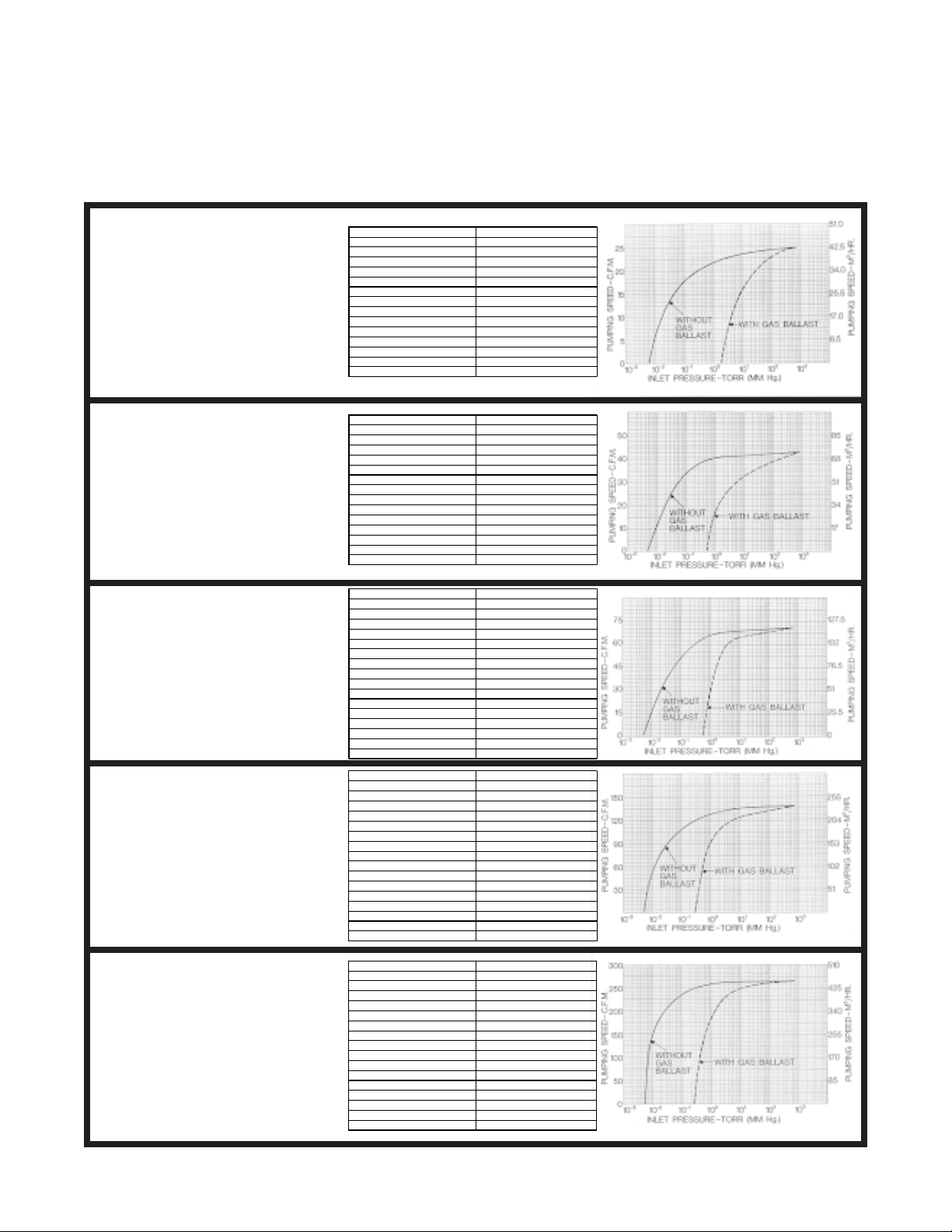
SPECIFICATIONS AND PERFORMANCE CURVES
UL TIMA TE VACU UM 10 MICRONS HG. OR LESS
DISPLACE MENT - CU. FT. 30 CFM
PUMP SPEED 800 RPM
MOTOR 1.5 HP
MOTOR SPE ED 1800 RPM SYNC.
ST D. ELECTRICAL SPECS. 3/60/230/460
PIPE CONNECTIONS
SUCTION 2" STD. FLG.
DISCHARG E 1-1/4" NPT
OIL CAPA CITY 1/2 GAL. (2 LITERS)
NET WEIG HT 315 LBS. (143 KG.)
SHIPPING WE IGHT 390 LBS. (177 KG.)
HEIGHT 30" (762 MM)
FLOOR SPACE 15-1/2" X 16 -3/4" (394 X 425 MM)
COOLING AIR COOLED
MODEL 146H-13
UL TIMA TE VACU UM 10 MICRONS HG. OR LESS
DISPLACE MENT - CU. FT. 50 CFM
PUMP SPEED 610 RPM
MOTOR 2 HP
MOTOR SPE ED 1800 RPM SYNC.
ST D. ELECTRICAL SPECS. 3/60/230/460
PIPE CONNECTIONS
SUCTION 1-1/2" S TD FLG.
DISCHARG E 1-1/2" NPT
OIL CAPA CITY 1-1/4 GAL. (5 LITERS)
NET WEIG HT 345 LBS. (157 KG.)
SHIPPING WE IGHT 435 LBS. (197 KG.)
HEIGHT 32" (813 MM)
FLOOR SPACE 27-1/4" X 18 -7/8" (421 X 486 MM)
COOLING AIR COOLED
UL TIMA TE VACU UM 10 MICRONS HG. OR LESS
DISPLACE MENT - CU. FT. 80 CFM
PUMP SPEED 490 RPM
MOTOR 3 HP
MOTOR SPE ED 1800 RPM SYNC.
ST D. ELECTRICAL SPECS. 3/60/230/460
PIPE CONNECTIONS
SUCTION 2" STD FLG.
DISCHARG E 1-1/2" NPT
WATER INLET 1/2" NPT
WATER OUTLET 1/2" NPT
OIL CAPA CITY 2-1/2 GAL. (10 LITERS)
NET WEIG HT 565 LBS (256 KG.)
SHIPPING WE IGHT 675 LBS. (306 KG.)
HEIGHT 38 -7 /8" (987 MM)
FLOOR SPACE 23-1/2" X 20 -1/8" (597 X 511 MM)
COOLING WATER
UL TIMATE VACUUM10 MICRONS HG. OR LESS
DISPLACE MENT - CU. FT. 150 CFM
PUMP SPEED500 RPM
MOTOR 7-1/2 HP
MOTOR SPEED1800 RPM SYNC.
ST D. ELECTRICAL SPECS. 3/60/230/460
PIPE CONN ECT IO NS
SUCTION 3" FLANGED
DISCHA R GE 2" SCREWED
WATER INL ET 1/2" NPT
WATER OUTLET 1/2" NPT
OIL CAPA CITY 4 GAL. (15 LITERS)
NET WEIG HT 950 LBS (431 KG.)
SHIPPING WE IG HT 1075 LBS. (488 KG.)
HEIGHT 43-1/2" (1105 MM)
FLOOR SPACE 26-1/4 X 24 (667 X 610 MM)
COOLIN G WATER
UL TIMA TE VACU UM 10 MICRONS HG. OR LESS
DISPLACE MENT - CU. FT. 300 CFM
PUMP SPEED 490 RPM
MOTOR 10 HP
MOTOR SPE ED 1800 RPM SYNC.
ST D. ELECTRICAL SPECS. 3/60/230/460
PIPE CONNECTIONS
SUCTION 4" FLANGED
DISCHARG E 3" SCREWED
WATER INLET 1/2" NPT
WATER OUTLET 1/2" NPT
OIL CAPA CITY 12 GAL. (46 LITERS )
NET WEIG HT 1750 LBS. (794 KG.)
SHIPPING WE IGHT 19 75 LBS. (896 KG.)
HEIGHT 51 -3 /4" (1314 MM )
FLOOR SPACE 40-1/4" X 25-5/8" (1022 X 6 51 MM)
COOLING WATER
MODEL 148H-10
MODEL 149H-11
MODEL 212H-11
MODEL 412H-11
This manual suits for next models
4
Table of contents
Popular Water Pump manuals by other brands

SKC
SKC 210-1000 Series operating instructions

Waspper
Waspper WP20/B instruction manual

ProMinent
ProMinent DULCO Trans 41/1000 PVDF Assembly and operating instructions

Crane
Crane Barnes EcoTRAN Installation & operation manual

Liberty Pumps
Liberty Pumps HT40 Series installation manual

Speck
Speck BADU translation of original operation manual

GORMAN-RUPP
GORMAN-RUPP AMT 489 Series Specifications information and repair parts manual

AMT
AMT 4410-95 Specifications information and repair parts manual

AquaCare
AquaCare 402-100 instruction manual

BUSCH
BUSCH Fossa FO 0015 A instruction manual

KSB
KSB Omega Installation & operating manual

INTERSOL
INTERSOL ARO 66615 C Series Operator's manual


