INTERSOL ARO 66615 C Series User manual
INGERSOLL RAND COMPANY LTD
209 NORTH MAIN STREET - BRYAN, OHIO 43506
(800) 495-0276 FAX (800) 892-6276 © 2015 CCN 81660219
arozone.com
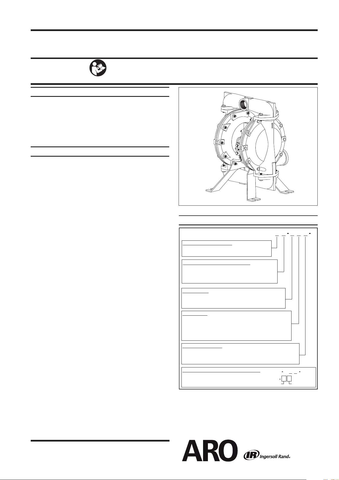
OPERATOR’S MANUAL 66615X-X-C
INCLUDING: OPERATION, INSTALLATION & MAINTENANCE RELEASED: 5-31-88
REVISED: 5-11-15
(REV. AE)
1-1/2” DIAPHRAGM PUMP
1:1 RATIO (METALLIC)
READ THIS MANUAL CAREFULLY BEFORE INSTALLING,
OPERATING OR SERVICING THIS EQUIPMENT.
It is the responsibility of the employer to place this information in the hands of the operator. Keep for future reference.
SERVICE KITS
Refer to the Model Description Chart to match the pump material op-
tions.
637118-C for air section repair (see page 6).
637124-XX for uid section repair (see page 4).
637155 Abrasion Resistant Conversion Kit is available for use in heavy
and abrasive material applications (see page 4).
PUMP DATA
Models. . . . . . . . . .see “Model Description Chart” for“-XXX”
Pump Type. . . . . .Metallic Air Operated Double Diaphragm
Materialsee . . . . .“Model Description Chart”
Weight . . . . . . Aluminum . . . . . . 51.54 lbs (23. 4 kgs)
Cast Iron. . . . . . . . 79.54 lbs (36.1 kgs)
Stainless Steel . . 84.54 lbs (38.3 kgs)
[add 23 lbs (10.4 kgs) for cast iron air motor section]
Maximum Air Inlet Pressure ........ 120 psig (8.3 bar)
Maximum Material Inlet Pressure. . . 10 psig (0.69 bar)
Maximum Outlet Pressure ......... 120 psig (8.3 bar)
Maximum Flow Rate (ooded inlet) 90 gpm (340.7 lpm)
Displacement / Cycle @ 100 psig
Standard Diaphragm . . . . . . 0.64 gal. (2.42 lit.)
Composite PTFE Diaphgram 0.40 gal. (1.52 lit.)
Maximum Particle Size ............. 1/4” dia. (6.4 mm)
Maximum Temperature Limits (diaphragm / ball / seat
material)
Acetal . . . . . . . . . . . . . . . . . . 10º to 180º F (-12º - to 82º C)
E.P.R . . . . . . . . . . . . . . . . . . -60º to 280º F (-51º - to 138º C)
Hytrel® ................. -20º to 180º F (-29º - to 82º C)
Kynar® PVDF. . . . . . . . . . . . 10º to 200º F (-12º- to 93º C)
Neoprene . . . . . . . . . . . . . . 0º to 200º F (-18º- to 93º C)
Nitrile . . . . . . . . . . . . . . . . . . 10º to 180º F (-12º- to 82º C)
Polypropylene . . . . . . . . . . 35º to 175º F (2º- to 79º C)
Polyurethane . . . . . . . . . . . 10º to 150º F (-12º- to 66º C)
PTFE . . . . . . . . . . . . . . . . . . 40º to 225º F (4º- to 107º C)
Santoprene®. . . . . . . . . . . . -40º to 225º F (-40º- to 107º C)
Viton® . . . . . . . . . . . . . . . . . . -40º to 350º F (-40º- to 177º C)
Dimensional Data............ seepage8
Noise Level @ 70 psig- 60 cpm. . . . 80.5 dB(A)
Tested with 350-568 muer installed.
The pump sound pressure levels published here have been updated to an Equivalent Con-
tinuous Sound Level (LA
eq
) to meet the intent of ANSI S1.13-1971, CAGI-PNEUROP S5.1 using
four microphone locations.
NOTICE: All possible options are shown in the chart. However, certain
combinations may not be recommended, consult a representative or the
factory if you have questions concerning availability.
MODEL DESCRIPTION CHART
6661
X
X
X
X
X
C
6661XX X X X C
637124
X X
DiaphragmBall
FLUID SECTION SERVICE KIT SELECTION
EXAMPLE: MODEL # 666150-361-C
Fluid Section Service Kit # 637124-61
CENTER BODY MATERIAL
FLUID CAP / MANIFOLD MATERIAL
5 - Aluminum, NPTF 7 - Aluminum, BSP
6 - Cast Iron, NPTF 8 - Cast Iron, BSP
Seat Material
1 - Aluminum 4 - Kynar PVDF
2 - 316Stainless Steel 5 - Carbon Steel
3 - Polypropylene
Ball Material
8 - 440 Stainless Steel
0 - Aluminum A - Aluminum
(Steel Hardware) (Stainless Steel Hardware)
1 - Stainless Steel B - Stainless Steel
2 - CastIron C - Cast Iron
1 - Neoprene 6 - Acetal
2 - Nitrile 8 - Polyurethane
3 - Viton A - Stainless Steel
4 - PTFE C - Hytrel
5 - E.P.R. E - Santoprene
Diaphragm Material
1 - Neoprene
2 - Nitrile
4 - PTFE / Santoprene
3 - Viton
5 - E.P.R.
6 - Composite PTFE
9 - Hytrel
B - Santoprene
66615X-XXX-C
1-1/2” DIAPHRAGM PUMP
Figure 1
Page 2 of 8 66615X-X-C (en)66615X-X-C (en)
OPERATING AND SAFETY PRECAUTIONS
READ, UNDERSTAND, AND FOLLOW THIS INFORMATION TO AVOID INJURY AND PROPERTY DAMAGE.
EXCESSIVE AIR PRESSURE
STATIC SPARK
HAZARDOUS MATERIALS
HAZARDOUS PRESSURE
WARNING
EXCESSIVE AIR PRESSURE. Can cause personal
injury, pump damage or property damage.
Do not exceed the maximum inlet air pressure as stated on
the pump model plate.
Be sure material hoses and other components are able to
withstand uid pressures developed by this pump. Check
all hoses for damage or wear. Be certain dispensing device
is clean and in proper working condition.
WARNING
STATIC SPARK. Can cause explosion resulting
in severe injury or death. Ground pump and pumping
system.
Sparks can ignite ammable material and vapors.
The pumping system and object being sprayed must be
grounded when it is pumping, flushing, recircula ing or
spraying ammable materials such as paints, solvents, lac-
quers, etc. or used in a location where surrounding atmo-
sphere is conducive to spontaneous combustion. Ground
the dispensing valve or device, containers, hoses and any
object to which material is being pumped.
Use the pump grounding screw terminal provided. Use ARO
®part no. 66885-1 ground kit or connect a suitable ground
wire (12 ga. minimum) to a good earth ground source.
Secure pump, connections and all contact points to avoid
vibration and generation of contact or static spark.
Consult local building codes and electrical codes for spe-
cic grounding requirements.
Aftergrounding, periodically verify continuity of electrical-
path to ground. Test with an ohmmeter from each compo-
nent (e.g., hoses, pump, clamps, container, spray gun, etc.)
to ground to ensure continuity. Ohmmeter should show 0.1
ohms or less.
Submerse the outlet hose end, dispensing valve or device
in the material being dispensed if possible. (Avoid free
streaming of material being dispensed.)
Use hoses incorporating a static wire.
Use proper ventilation.
Keep inflammables away from heat, open flames and
sparks.
Keep containers closed when not in use.
WARNING
Pump exhaust may contain contaminants.
Can causesevere injury. Pipe exhaust away from work are a
and personnel.
In the event of a diaphragm rupture, material can be forced
out of the air exhaust muer.
Pipe the exhaust to a safe remote location when pumping
hazardous or inammable materials.
Use a grounded 3/4” minimum i.d. hose between the pump
and the muer.
WARNING
HAZARDOUS PRESSURE. Can result in serious
injury or property damage. Do not service or clean pump,
hoses or dispensing valve while the system is pressurized.
Disconnect air supply line and relieve pressure from the
system by opening dispensing valve or device and / or
carefully and slowly loosening and removing outlet hose or
piping from pump.
WARNING
HAZARDOUS MATERIALS.
Can cause serious
injury or property damage. Donot attempt to return
a pump to the factory or service center that contains
hazardous material. Safe handling practices must comply
with local and national laws and safety code requirements.
Obtain Material Safety Data Sheets on all materials from
the supplier for proper handling instructions. Obtain Mate-
rial Safety Data Sheets on all materials from the supplier
for proper handling instructions.
WARNING
EXPLOSION HAZARD. Models containing
aluminum wetted parts cannot be used with
1,1,1-trichloroethane, methylene chloride or other
halogenated hydrocarbon solvents which may react
and explode.
Check pump motor section, fluid caps, manifolds and all
wetted parts to assure compatibility before using with sol-
vents of this type.
CAUTION
Verify the chemical compatibility of the pump
wetted parts and the substance being pumped, ushed
or recirculated. Chemical compatibility may change with
temperature and concentration of the chemical(s) within
the substances being pumped, ushed or circulated.
For specic uid compatibility, consult the chemical
manufacturer.
CAUTION
Maximum temperatures are based on
mechanical stress only. Certain chemicals will signicantly
reduce maximum safe operating temperature. Consult
the chemical manufacturer for chemical compatibility and
temperature limits. Refer to PUMP DATA on page 1 of this
manual.
CAUTION
Be certain all operators of this equipment
have been trained for safe working practices, understand
it’s limitations, and wear safety goggles / equipment when
required.
CAUTION
Do not use the pump for the structural
support of the piping system. Be certain the system
components are properly supported to prevent stress on
the pump parts.
Suction and discharge connections should be flexible con-
nections (such as hose), not rigid piped, and should be com-
patible with the substance being pumped.
CAUTION
Prevent unnecessary damage to the pump.
Do not allow pump to operate when out of material for
long periods of time.
Disconnect air line from pump when system sits idle for
long periods of time.
CAUTION
Use only genuine ARO replacement parts to
assure compatible pressure rating and longest service life
.
NOTICE
Replacement warning labels are available
upon request: “Static Spark” (93616-1) &“Diaphragm
Rupture” (93122).
WARNING
=
Hazards or unsafe practices which
could result in severe personal injury,
death or substantial property damage.
CAUTION
=Hazards or unsafe practices which
could result in minor personal in-
jury, product or property damage.
NOTICE
=Important installation, operation or
maintenance information.

66615X-X-C (en) Page 3 of 8Page 3 of 8
Viton®and Hytrel®are registered trademarks of the DuPont Company. Kynar®is a registered trademark of Penwell Corp. ARO®is a registered trademark of Ingersoll Rand Company
Santoprene®is a registered trademark of Monsanto Company, licensed to Advanced Elastomer Systems, L.P. Key-Lube®is a registered trademark of Key Industries
GENERAL DESCRIPTION
The ARO diaphragm pump oers high volume delivery even at
low air
pressure and a broad range of material compatibility
options available. Refer to the model and option chart. ARO
pumps feature stall resistant design, modular air motor /
uid sections. Air operated double diaphragm pumps utilize
a pressure dierential in the air chambers to alternately cre-
ate suction and positive uid pressure in the uid chambers,
valve checks ensure a positive ow of uid. Pump cycling will
begin as air pressure is applied and it will continue to pump
and keep up with the demand. It will build and maintain line
pressure and will stop cycling once maximum line pressure is
reached (dispensing
device closed) and will resume pumping
as needed.
AIR AND LUBE REQUIREMENTS
EXCESSIVE AIR PRESSURE. Can cause personal injury, pump
damage or property damage.
A filter capable of filtering out particles larger than 50
microns should be used on the air supply. There is no lu-
brication required other than the “O” ring lubricant which
is applied during assembly or repair.
If lubricated air is present,makesure that it is compatible
with the “O” rings and seals in the air motor section of the
pump.
OPERATING INSTRUCTIONS
Always flush the pump with a solvent compatible with
the material being pumped if the material being pumped
is subject to “setting up” when not in use for a period of
time.
Disconnect the air supply from the pump if it is to be inac-
tive for a few hours.
The outlet material volume is governed not only by the
air supply, but also by the material supply available at the
inlet. The material supply tubing should not be too small
or restrictive. Be sure not to use hose which might co
lapse.
When the diaphragm pump is used in a forced-feed
(ooded inlet) situation, it is recommended that a “Check
Valve” be installed at the air inlet.
Secure the diaphragm pump legs to a suitable surface to
ensure against damage by vibration.
MAINTENANCE
Refer to the part views and descriptions as provided on pages
4 through 7 for parts identification and service kit informa-
tion.
Certain ARO “Smart Parts” are indicated which should be
available for fast repair and reduction of down time.
Service kits are divided to service two separate diaphragm
pump functions: 1. AIR SECTION, 2. FLUID SECTION. The
FLUID SECTION is divided further to match typical part
MATERIAL OPTIONS.
Provide a clean work surface to protect sensitive internal
moving parts from contamination from dirt and foreign
matter during service disassembly and reassembly.
Keep good records of service activity and include pump
in preventive maintenance program.
Before disassembling, empty captured material in the
outlet manifold by turning the pump upside down to
drain material from the pump.
FLUID SECTION DISASSEMBLY
Remove top manifold(s).
Remove (22) balls, (19) “O” rings and (21) seats.
Remove (15) uid caps.
NOTE: Only PTFE diaphragm models use a primary dia-
phragm (7) and a backup diaphragm (8). Refer to the auxiliary
view in the Fluid Section illustration.
For 6661XX-XX6-C:
4. Remove (7)diaphragm,(5)washers and (30)shims.
For other models:
5. Remove the (14) screws, (6) washers, (7) or (7 / 8)
diaphragms and (5) washers.
6. Remove (3) “O” rings.
NOTE: Do not scratch or mar the surface of (1) diaphragm
rod.
FLUID SECTION REASSEMBLY
Reassemble in reverse order.
Clean and inspect all parts. Replace worn or damaged
parts with new parts as required.
Lubricate (1) diaphragm rod and (2) “O” ring with Key-
Lube “O” ring lube.
Use AROpn / 98931-T bullet (installation tool) to aid in
installation of (2) “O” ring on (1) diaphragm rod.
For 6661XX-XX6-C:
Attach a regulated airline to the pump inlet; gradually
increasing the air pressure (6-8 psi) to check which side of
the pump with air blowing out, and then shut down the
air supplier.
Fasten (7) diaphragm with (5) washer into (1) diaphragm
rod, and insert them into (101) Center body from the
chamber identied with blowing air in the previous step.
Install (15) uid cap.
Thread the other side of (7) diaphragm with (5) washer
into (1) diaphragm rod, but do not tighten it.
Record the angle for the misalignment between (7) dia-
phragm hole and (101) center body holes, then unthread
the (7) diaphragm and place proper Qty. of (30) shims
between (5) washer and (1) diaphragm rod.
Attach a regulated airline to the pump inlet, gradually
increasing the air pressure (6-8 psi) until the diaphragm
shift to the other site, shut down the air supply.
Install the second (15) uid cap.
NOTE: For details, refer to service kits manual 48495949.
For other models:
Be certain (7) or (7 / 8) diaphragm(s) align properly with
(15) uid caps before making nal torque adjustments on
bolt and nuts to avoid twisting the diaphragm.
For models with PTFE diaphragms: Item (8) Santoprene
diaphragm is installed with the side marked “AIR SIDE”
towards the pump center body. Install the PTFE
diaphragm with the side marked “FLUID SIDE” towards the
uid cap.
Check all torque settings after pump has been re-started
and run a while.
1.
2.
3.
Page 4 of 8 66615X-X-C (en)66615X-X-C (en)
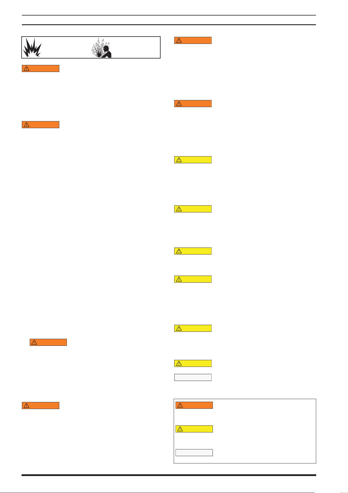
PARTS LIST / 66615X-X-C FLUID SECTION
MATERIAL CODE
[A] = Aluminum
[B] = Nitrile
[C] = Carbon Steel
[CI] = Cast Iron
[Co]= Copper
[CP] = Composite PTFE
[D] = Acetal
[E] = E.P.R.
[H] = Hytrel
[K] = Kynar PVDF
[P] = Polypropylene
[SH] = Hard Stainless Steel
[Sp] = Santoprene
[SS] = Stainless Steel
[T] = PTFE
[U] = Polyurethane
[V] = Viton
637155
ABRASION RESISTANT
CONVERSION KIT
Includes:
93266 (4) [SH] Seat
92757-8 (4) [U] Ball
COMMON PARTS
The quantity is between 0 to 5, shims are not shown in the exploded view.
"Smart Parts” keep these items on hand in addition to the Service Kits for fast repair and
reduction of down time.
# For service, shim pack 48499339 can be purchased. Refer to service kits manual 48495949
for details.
For 6661XX-XX6-C, on the uid side, washer (6), (9) and screw (14) are not needed.
Service Note: Part no. 98931-T installation tool is available separately for use with items 1 and 2.
Item Description (size in inches) Qty Part No. [Mtl]
1 Rod (6661XX-XX6-C) (1) 48489819 [C]
(other models) (1) 98720-1 [C]
2 ‘‘O” Ring (3/32” x 1” o.d.) (1) Y330-117 [B]
6 Plate (uid side)(2) 92775 [SS]
(models 6661X0 only) (2) 92752 [C]
Item Description (Size in inches) Qty Part No. [Mtl]
9 Washer (0.630” i.d.)(2) 93065 [SS]
14 Screw (5/8” - 18 x 1-1/2”)(2) Y5-107-T [SS]
43 Ground Lug (see page 7) (1) 93004 [Co]
30 Shim (6661XX-XX6-C) () 48499875 # [C]
637124-XX Fluid Section Service Kits include: BALLS (see Ball Option, refer to -XX in chart below), DIAPHRAGMS (see Diaphragm Option,
refer to -XX in chart below), 93706-1 Key-Lube grease packet, plus items: 2, 3, 9 and 19.
SEAT OPTIONS
6661XX-XXX-C
BALL OPTIONS
6661XX-XXX-C
“21”
“22” (1-1/4” dia.)
-XXX Seat Qty [Mtl] -XXX Ball Qty [Mtl] -XXX Ball Qty [Mtl]
-1XX 92760 (4) [A] -X1X 92757-1 (4) [N] -X8X 92757-8 (4) [U]
-2XX 92776 (4) [SS] -X2X 92757-2 (4) [B] -XAX 94804 (4) [SS]
-3XX 92924 (4) [P] -X3X 92757-3 (4) [V] -XCX 92757-C (4) [H]
-4XX 94514 (4) [K] -X4X 92757-4 (4) [T] -XEX 92757-A (4) [Sp]
-5XX 95676 (4) [C] -X5X 92757-5 (4) [E]
-8XX 93266 (4) [SH] -X6X 92757-6 (4) [D]
DIAPHRAGM OPTIONS 6661XX-XXX-C
SERVICE KIT
“7”
“8”
“3” (1/16” x 3/4” o.d.)
“19”
-XX = (Ball)
-XXX -XX = (Diaphragm) Diaphragm [Qty] [Mtl] Diaphragm [Qty] [Mtl] "O” Ring [Qty] [Mtl] "O” Ring [Qty] [Mtl]
-XX1 637124-X1 92755-1 (2) [N] --- [B] Y325-16 (4) [B] Y325-230 (4) [B]
-XX2 637124-X2 92755-2 (2) [B] --- [B] Y325-16 (4) [B] Y325-230 (4) [B]
-XX3 637124-X3 92755-3 (2) [V] --- [T] Y328-16 (4) [T] Y327-230 (4) [V]
-XX4 637124-X4 94617 (2) [T] 94616 (2) [Sp] Y328-16 (4) [T] Y220-230 (4) [T]
-XX5 637124-X5 92755-5 (2) [E] --- [T] Y328-16 (4) [T] 92761 (4) [E]
-XX6 48496806 48490064 (2) [CP] --- --- --- --- --- Y220-230 (4) [T]
-XX9 637124-X9 94615-9 (2) [H] --- [T] Y328-16 (4) [T] Y327-230 (4) [V]
-XXB 637124-XB 94615-A (2) [Sp] --- [T] Y328-16 (4) [T] 92761 (4) [E]
WETTED PARTS OPTIONS 6661XX-XXX-C
Aluminum
6661X0-X, 6661XA-X
Stainless Steel
6661X1-X, 6661XB-X
Cast Iron
6661X2-X, 6661XC-X
NPTF BSP NPTF BSP NPTF BSP
Item Description (Size) Qty Part No. Part No. [Mtl] Part No. Part No. [Mtl] Part No. Part No. [Mtl]
15 Fluid Cap (2) 92750 92750 [A] 92773 92773 [SS] 92778 92778 [CI]
16 Manifold (2) 92749 92749-1 [A] 92774 92774-1 [SS] 92777 92777-1 [CI]
HARDWARE OPTIONS 6661XX-XXX-C
Item Description (Size) Qty
Carbon Steel
6661X0-, 1-, 2-
Stainless Steel
6661XA-, B-, C
Part No. [Mtl] Part No. [Mtl]
5Plate (air side) (6661XX-XX6-C) (2) 48496673 [C] 48496673 [SS]
(Other models) (2) 92752 [C] 92775 [SS]
26 Bolt (3/8” - 16 x 1-1/4”) (8) Y6-66-C [C] Y6-66-T [SS]
27 Bolt (5/16” - 18 x 2-1/4”) (4) Y6-510-C [C] Y6-510-T [SS]
29 Nut (5/16” - 18) (20) Y12-5-C [C] Y12-5-S [SS]
32 Leg (2) 92759 [C] 92759-1 [SS]
59 Bolt (5/16” - 18 x 2”)(6661XX-XX6-C)
(16) 47512837001 [C] 47510437001 [SS]
(Other models) (16) 93608 [C] Y6-59-T [SS]
66615X-X-C (en) Page 5 of 8Page 5 of 8
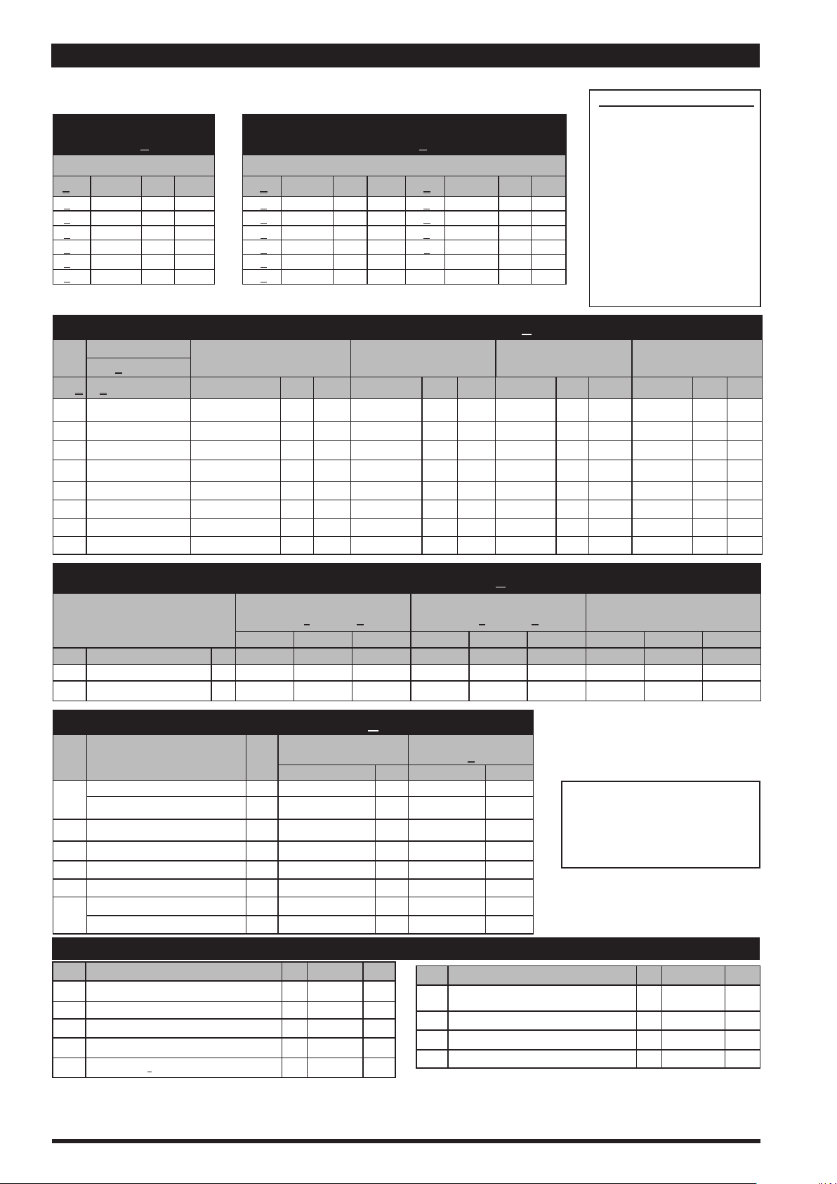
PARTS LIST / 66615X-X-C FLUID SECTION
1
29 ,U
FOR THE
AIR MOTOR SECTION
SEE PAGES 6&7
.,
NOTE: DO NOT OVERTIGHTEN FASTENERS.
(14) Diaphragm screw, 65 - 70 ft lbs (88.1 - 94.9 Nm.).
(26) Bolts, 240 - 280 in. lbs (27.1 - 31.6 Nm).
(29) Nuts, 120 - 140 in. lbs (13.6 - 15.8 Nm).
k
Apply Key-Lubetoall“O”rings,“U” Cups & mating parts.
z
Apply Loctite
271 to threads
U
Apply anti-seize compound to threads and bolt and nut
ange heads which contact pump case when using
stainless steel fasteners.
View for 6661XX-XX4 -C (PTFEdiaphragm) congurationonly.
Tab
7
k3
COLOR CODE
�See item 8 in inset below.
21
19k
22
26 ,U
16
59U
15
22
21
19k
16
27U
32
14,z
9
6
5
2k
Tab
7
PTFE
(white)
Santoprene
8
(Green when used as backer)
Air Side
Fluid Side
Fluid Side
Air Side
Cross Section View of Diaphragms
5
7
2
3
4
1
8
6
TorqueSequence
901
3k
26,U
Figure 2
Acetal
E.P.R.
Hytrel
Neoprene
Nitrile
Santoprene
PTFE
Polyurethane
Viton
N/A
Blue(-)
Cream
Green(-)
Black
Tan
�
White
N/A
Yellow(-)
(-)Stripe
Orange
Blue(•)
Cream
Green(•)
Red(•)
Tan
White
Red
Yellow(•)
(•)Dot
Material
Diaphragm
color
Ball
Color
LUBRICATION / SEALANTS
TORQUE REQUIREMENTS
Page 6 of 8 66615X-X-C (en)66615X-X-C (en)
“Smart Parts” Keep these items on hand in addition to the Service Kits for fast repair and reduction of down time.
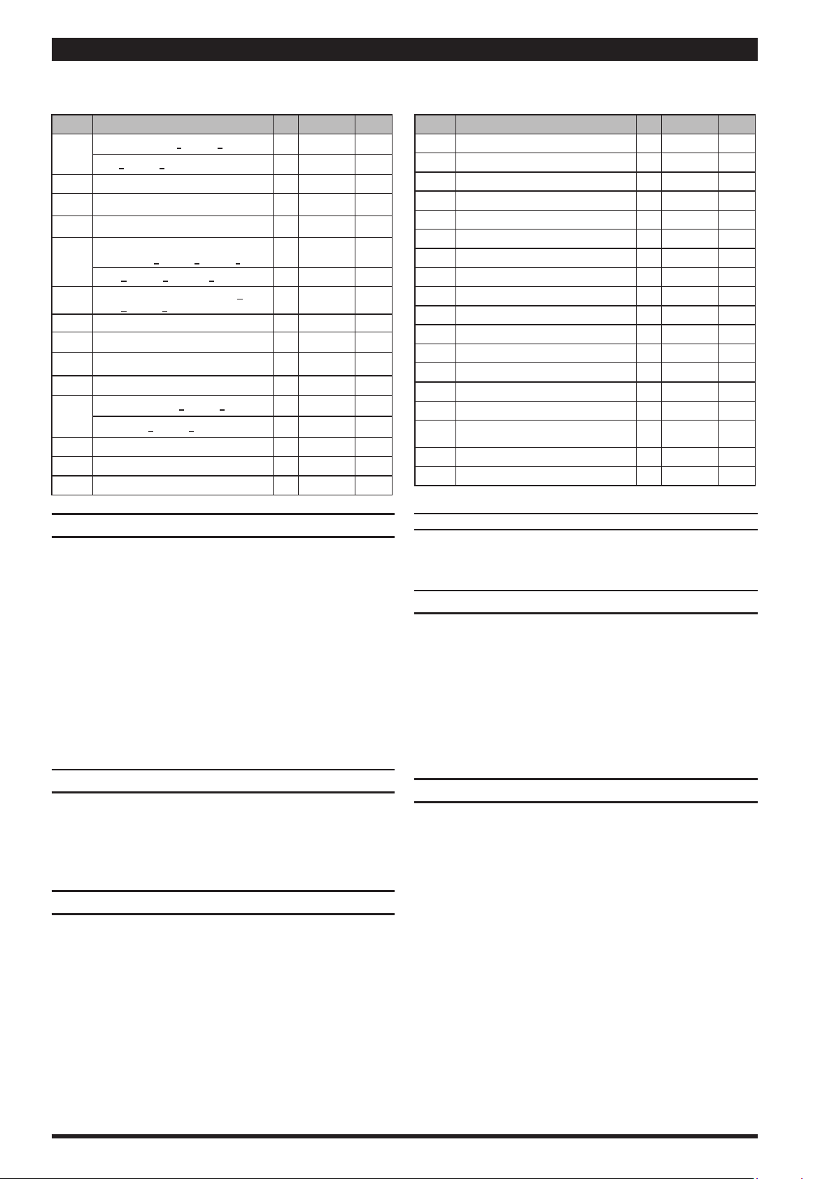
PARTS LIST / 66615X-X-C AIR SECTION
Indicates parts included in 637118-C Air Section Service Kit.
SERVICE KIT NOTE: Service Kit 637118-C is a general repair kit for all 1” and larger ARO diaphragm pump air motors. It contains extra “O” Rings and other
parts that may not be needed to service this model.
Item Description (size) Qty Part No. [Mtl]
101 Motor Body(66615X-X, 66617X-X) (1) 94744 [A]
(66616X-X, 66618X-X) (1) 94742 [CI]
102 ‘‘O” Ring(1/16” x 1-1/4” o.d.) (2) Y325-24 [B]
103 Sleeve (1) 94528 [D]
104 Retaining Ring, TruArc (1-5/32” i.d.) (2) Y145-26 [C]
105
Screw / Lockwasher (1/4”- 20 x 5/8”)
(models 6661X0-X, 6661X1-X, 6661X2-X) (8) 93860 [C]
6661XA-X, 6661XB-X, 6661X5C-X) (8) Y6-42-T [SS]
106 Lockwasher (1/4”) (models 6661XA-X,
6661XB-X, 6661XC-X only) (8) Y14-416-T [SS]
107 Plate (2) 93707-1 [SS]
108 Gasket (with notch) (1) 92878 [B/Ny]
109 Piston (1) 92011 [D]
110 “U” Cup (3/16” x 1-3/8” o.d.) (1) Y186-51 [B]
111 Spool (models 66615X-X, 66617X-X) (1) 92005 [A]
(models 66616X-X, 66618X-X) (1) 93047 [C]
112 Washer (1.557” o.d.) (5) 92877 [Z]
113 “O” Ring (small) (1/8” x 1-1/4” o.d.) (5) Y325-214 [B]
114 “O” Ring (large) (3/32” x 1-9/16” o.d.) (6) Y325-126 [B]
Item Description (size) Qty Part No. [Mtl]
115 Spacer (4) 92876 [Z]
116 Spacer (1) 92006 [Z]
117 Gasket (1) 92004 [B/Ny]
118
Pilot Rod (1) 93309-2 [C]
119 “O” Ring (1/8” x 3/4” o.d.) (4) 93075 [U]
120 Spacer (3) 115959 [Z]
121 Sleeve Bushing (2) 98723-2 [Bz]
122
“O” Ring (3/32” x 9/16” o.d.) (2) 94820 [U]
123 Screw (#8 - 32 x 3/8”) (4) Y154-41 [C]
126 Pipe Plug (1/2 - 14 P.T.F. x 17/32”) (1) Y227-5-L [C]
127 90º Street Elbow (3/4 - 14 NPTF) (1) Y43-5-C [C]
128 Pipe Plug (1/8 - 27 P.T.F. x 1/4”) (1) Y227-2-L [C]
197 Button Head Screw (1/4” - 20 x 1/4”) (2) 94987 [SS]
198 Button Head Screw (1/4” - 20 x 3/8”) (1) 94987-1 [SS]
201 Muer (1) 350-568
231 Pipe Plug (1/4 - 18 NPTF x 0.41”) (models
66616X-X and 66618X-X only) (2) Y17-51-S [SS]
Key-Lube “O” Ring Lubricant (1) 93706-1
10 Pack of Key-Lube 637175
AIR MOTOR SECTION SERVICE
Service is divided into two parts - 1. Pilot Valve, 2. Major Valve.
GENERAL REASSEMBLY NOTES:
Air Motor Section Service is continued from Fluid Section
repair.
Inspect and replace old parts with new parts as
necessary. Look for deep scratches on metallic surfaces,
and nicks or cuts in “O” rings.
Take precautions to prevent cutting“O” rings upon
installation.
Lubricate“O” rings with Key-Lube.
Do not over-tighten fasteners, refer to torque specica-
tion block on view.
Make sure to torque all fasteners following restart.
PILOT VALVE DISASSEMBLY
Remove (104) retaining ring.
Remove (123) screws and (122) “O” rings.
Remove (118) piston rod, (121) sleeve bushing, (119)“O”
rings and (120) spacers from the (101) motor body.
Remove (103) sleeve and (102) “O” rings.
PILOT VALVE REASSEMBLY
Replace two (102) “O” rings if worn or damaged and re-
install (103) sleeve.
Install one of the (121) sleeve bushings, (119) “O” rings,
(120) spacers and the remaining (121) bushing.
3. Carefully push (118) pilot rod into bushings etc. and
retain on each end with the two (122) “O” rings, retain
with (123) screws.
4. Replace (104) retaining rings.
1.
2.
3.
4.
1.
2.
MATERIAL CODE
[A] = Aluminum [CI] = Cast Iron [SS] = Stainless Steel
[B] = Nitrile [D] = Acetal [U]= Polyurethane
[Bz] = Bronze [Ny] = Nylon [Z] = Zinc
[C] = Carbon Steel
MAJOR VALVE DISASSEMBLY
Remove (107) plate (or leg depending on model), (108
and 117) gaskets.
On the side opposite the air inlet, push on the inner di-
ameter of (111) spool. This will force the (109) piston out.
Continue pushing the (111) spool and remove. Check for
scratches and gouges.
Reach into the air section (exhaust side) and remove
(116) spacer, (115) spacers, (113)“O”rings, (114)“O”rings,
(112) washers, etc. Check for damaged“O” rings.
MAJOR VALVE REASSEMBLY
Replace (112) washer, (114) “O” ring and (113) “O” ring
onto (115) spacer and insert etc.
NOTE: Be careful to orient spacer legs away from block-
ing internal ports.
2. Lubricate and carefully insert (111) spool.
3. Install (117) gasket and (107).
4. Lubricate and install (110) packing cup and insert (109)
piston into (air inlet side) cavity, the (110) packing cup
lips should point outward.
5. Install (108) gasket and replace (107).
1.
2.
3.
1.
66615X-X-C (en) Page 7 of 8Page 7 of 8
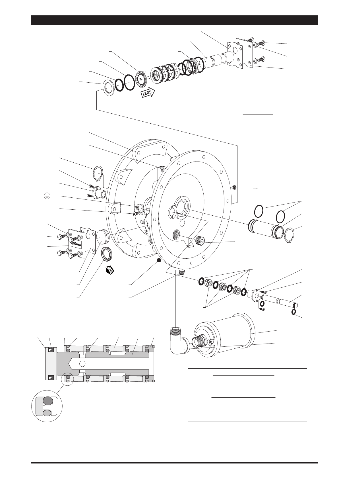
PARTS LIST / 66615X-X-C AIR SECTION
MAJOR VALVE
PILOT VALVE
118
111
112
113
114
116115
117
119
122
102
104
123
121
120
108
109
110
106
105
NOTE: DO NOT OVERTIGHTEN FASTENERS.
(105) 40 - 50 in. lbs (4.5 - 5.6 Nm).
LUBRICATION / SEALANTS
Apply Key-Lube to all “O” rings, “U” Cups & mating parts.
Apply Loctite 262 to threads.
Apply Loctite 271 to threads.
Apply Loctite 572 to threads.
See cross section detail, gure 4.
128
MAJOR VALVE CROSS SECTION DETAIL
109 110112 114113 115 111 116
Figure 4
107
126
BE CERTAIN TO ORIENT (115) SPACER LEGS
AWAY FROM BLOCKING INTERNAL PORTS
WHEN REASSEMBLING AIR SECTION.
197
198
101
231
104
103
107
106
105
123
121
197
43
201
127
Figure 3
TORQUE REQUIREMENTS
IMPORTANT

Page 8 of 8 66615X-X-C (en)
PN 97999-96
(Dimensions shown are for reference only, they are displayed in inches and millimeters (mm).
11-1/2” (292mm)
19-5/8”
(498mm)
18-3/8”
(467mm)
13-1/8” (333mm)
10-3/4” (273 mm)
12” (305 mm)
2-3/4”
(70mm)
9” (229mm)
1/2”Slot (14mm)
Material Outlet
Figure 5
7-5/8”
(194mm)
Air Inlet
1/2-14NPTF-1
Air Exhaust Thread
3/4-14NPTF-1
14-13/16” (376mm)
Material Outlet
1-1/2 - 11-1/2 NPTF - 1 (66615X-X-C, 66616X-X-C)
Rp 1-1/2 (1-1/2 - 11 BSP parallel) (66617X-X-C, 66618X-X-C)
1-1/2 - 11-1/2 NPTF - 1 (66615X-X-C, 66616X-X-C)
Rp 1-1/2 (1-1/2 - 11 BSP parallel)(66617X-X-C,66618X-X-C)
DIMENSIONAL DATA
Product discharged from exhaust outlet.
Check for diaphragm rupture.
Check tightness of (14) diaphragm screw.
Air bubbles in product discharge.
Check connections of suction plumbing.
Check “O” rings between intake manifold and uid caps.
Check tightness of (14) diaphragm screw.
Low output volume, erratic ow, or no ow.
Check air supply.
Check for plugged outlet hose.
Check for kinked (restrictive) outlet material hose.
Check for kinked (restrictive) or collapsed inlet material
hose.
Check for pump cavitation - suction pipe should be sized
at least as large as the inlet thread diameter of the pump
for proper ow if high viscosity uids are being pumped.
Suction hose must be a non-collapsing type, capable of
pulling a high vacuum.
Check all joints on the inlet manifolds and suction con-
nections. These must be air tight.
Inspect the pump for solid objects lodged in the dia-
phragm chamber or the seat area.
TROUBLE SHOOTING
Table of contents
Popular Water Pump manuals by other brands

Grundfos
Grundfos CRN MAGdrive Installation and operating instructions

ETATRON D.S.
ETATRON D.S. BT Operating instructions and maintenance

Pumpex
Pumpex K 80 Starting and operating instructions

Otto Bock
Otto Bock Harmony P3 4R147 Instructions for use

KitchenAid
KitchenAid 4176199 installation instructions

Saci
Saci OPTIMA Installation and maintenance manual


EINHELL
EINHELL GE-SP 18 LL Li Original operating instructions

SAMES KREMLIN
SAMES KREMLIN REXSON 2B225 user manual

ITT
ITT Bornemann SLH-4U operating instructions

Salamander Pumps
Salamander Pumps CT FORCE 15 PT Installation and warranty guide

Polaris
Polaris TBM 150 MH Series Installation, operation and maintenance manual

Sibata
Sibata LVS-30 Operation manual