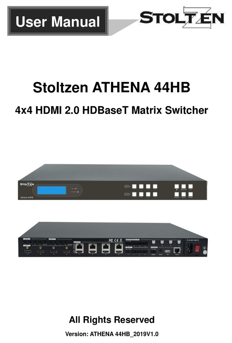
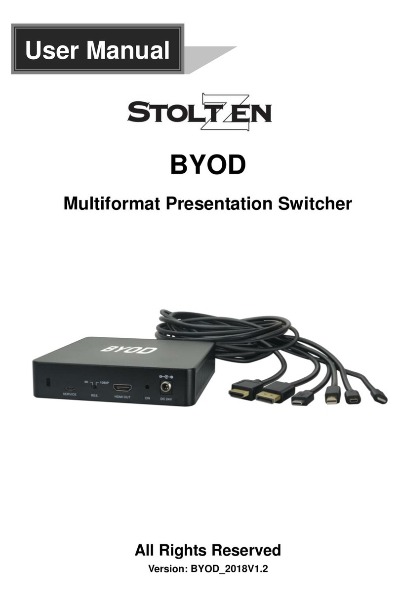
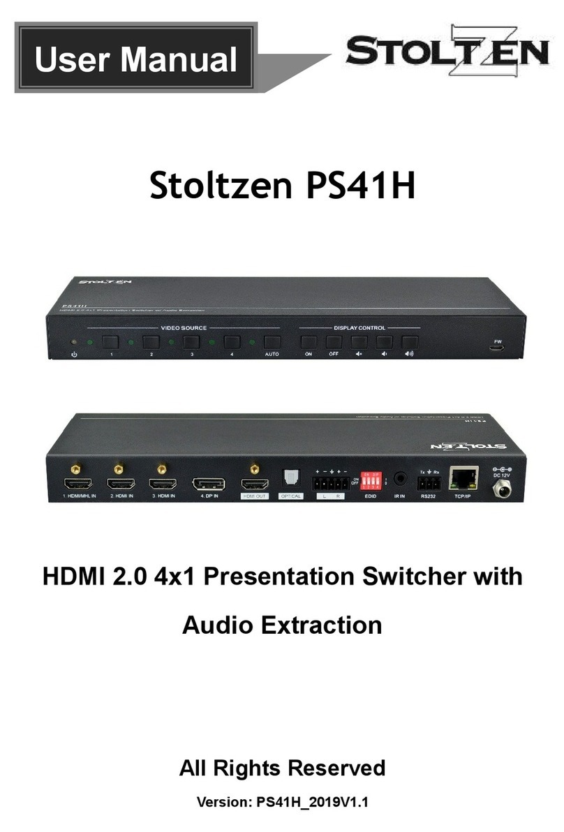
Stoltzen HuddleBox User manual

HuddleBox
All Rights Reserved
Version: HuddleBox_2023V1.13

All-in-one Meeting Room Switcher with USB-C & USB Hub
Preface
Read this user manual carefully before using the product. Pictures shown in this
manual are for reference only. Different models and specifications are subject to real
product.
This manual is only for operation instruction, please contact the local distributor for
maintenance assistance. In the constant effort to improve the product, we reserve the
right to make functions or parameters changes without notice or obligation. Please refer
to the dealers for the latest details.
FCC Statement
This equipment generates, uses and can radiate radio frequency energy and, if not
installed and used in accordance with the instructions, may cause harmful interference
to radio communications. It has been tested and found to comply with the limits for a
Class B digital device, pursuant to part 15 of the FCC Rules. These limits are designed
to provide reasonable protection against harmful interference in a commercial
installation.
Operation of this equipment in a residential area is likely to cause interference, in which
case the user at their own expense will be required to take whatever measures may be
necessary to correct the interference.
Any changes or modifications not expressly approved by the manufacturer would void
the user’s authority to operate the equipment.

All-in-one Meeting Room Switcher with USB-C & USB Hub
SAFETY PRECAUTIONS
To ensure the best from the product, please read all instructions carefully before using
the device. Save this manual for further reference.
1) Unpack the equipment carefully and save the original box and packing
material for possible future shipment.
2) Follow basic safety precautions to reduce the risk of fire, electrical shock,
and injury to persons.
3) Do not dismantle the housing or modify the module. It may result in
electrical shock or burn.
4) Using supplies or parts not meeting the products specifications may cause
damage, deterioration, or malfunction.
5) Refer all servicing to qualified service personnel.
6) To prevent fire or shock hazard, do not expose the unit to rain, moisture or
install this product near water.
7) Do not put any heavy items on the extension cable in case of extrusion.
8) Do not remove the housing of the device as opening or removing housing
may expose you to dangerous voltage or other hazards.
9) Install the device in a place with fine ventilation to avoid damage caused
by overheating.
10) Keep the module away from liquids.
11) Spillage into the housing may result in fire, electrical shock, or equipment
damage. If an object or liquid falls or spills on to the housing, unplug the
module immediately.
12) Do not twist or pull by force ends of the cable. It can cause malfunction.
13) Do not use liquid or aerosol cleaners to clean this unit. Always unplug the
power to the device before cleaning.
14) Unplug the power cord when left unused for a long period of time.
15) Information on disposal for scrapped devices: do not burn or mix with
general household waste, please treat them as normal electrical wastes.

All-in-one Meeting Room Switcher with USB-C & USB Hub
Table of Contents
1. Product Introduction ............................................................................................................ 5
1.1. Features .................................................................................................................... 5
1.2. Package List.............................................................................................................. 5
2. Specification ........................................................................................................................ 6
3. Panel Description ................................................................................................................ 8
3.1. Rear Panel ................................................................................................................ 8
3.2. Front Panel ................................................................................................................. 9
4. System Connection ........................................................................................................... 10
4.1. Usage Precaution.................................................................................................... 10
4.2. System Diagram...................................................................................................... 10
5. Button Control ................................................................................................................... 11
5.1. Manual Switching..................................................................................................... 11
6. GUI Control ....................................................................................................................... 11
6.1. Video Switching Setting........................................................................................... 12
6.1.1. Conference Mode .......................................................................................... 12
6.1.2. Manual Mode ................................................................................................ 13
6.1.3. Mirror Mode................................................................................................... 13
6.1.4. Matrix Mode .................................................................................................. 14
6.2. Audio Control Setting .............................................................................................. 15
6.3. Configuration........................................................................................................... 15
6.3.1. EDID Setting.................................................................................................. 15
6.3.2. Down-scaling Setting .................................................................................... 17
6.3.3. Working Status Setting.................................................................................. 17
6.4. CEC Control Setting ................................................................................................ 18
6.4.1. Source Control .............................................................................................. 18
6.4.2. Display Control .............................................................................................. 18
6.4.3. User-defined.................................................................................................. 19
6.5. USB HOST Setting.................................................................................................... 20
6.6. Network Setting........................................................................................................ 20
6.7. Access Setting......................................................................................................... 21
7. RS232 Control................................................................................................................... 22
7.1. RS232 Command.................................................................................................... 23
7.1.1. System Command......................................................................................... 23
7.1.2. Query Command........................................................................................... 24
7.1.3. Setting Command ......................................................................................... 24
7.1.4. EDID Command ............................................................................................ 25
7.1.5. CEC Command ............................................................................................. 26
8. Firmware Upgrade............................................................................................................. 27
9. Panel Drawing ................................................................................................................... 29
10. Troubleshooting and Maintenance .................................................................................. 29
11. Customer Service............................................................................................................ 31

5
All-in-one Meeting Room Switcher with USB-C & USB Hub
1. Product Introduction
The HuddleBox is a dedicated professional all-in-one meeting room switcher with USB-
C & USB Hub for video conference.
It’s an HDMI2.0 4x2 Matrix Switcher, features USB-C connectivity for a simplified
transmission of 4K video, audio, control signals and power providing meeting
participants with easy host switching, utilizing data speeds of up to 5 Gbps under the
USB 3.2 Gen1 providing video resolution capabilities up to 4K@60Hz at 4:4:4.
For the USB-C input ports, one provides up to 65W charging, the other only provides
external 5V 2A charging for mobile phones.
Easy control, it supports TCP/IP(GUI), RS232 and front buttons controlling.
1.1. Features
Multiple USB 3.2 Gen 1 connectivity for any type of USB devices (Camera,
speakerphone, touch monitor, USB-HID devices etc.…)
Separate USB 3.2 Host switching layer for multiple USB hosts and USB devices
Supports HDMI2.0, 4K@60 4:4:4,up to 18G
HDCP2.2 and backward compliant.
Supports USB-C up to 4K/60Hz 4:2:0 with 65W charging (only for the first port).
One USB3.2 (5Gbps) KVM console HUB and control up to 4 directly connected
computers
USB-C supports DP1.2 MST function.
Supports 4K to 1080p down-scaling without frame rate change.
CEC and display control & EDID management
Controllable via front panel, RS232, TCP/IP (GUI) and Auto-switching.
Firmware upgraded by TCP/IP (GUI)
1.2. Package List
Contents
1x Huddle Box
2x Mounting Ears with 4 Screws
4 x Rubber feet
1x RS232 Cable (3-pin to DB9)
1 x 5-pin phoenix connector
1x 100Watt USB-C Power Supply (20V 5A)
1 x User Manual

6
All-in-one Meeting Room Switcher with USB-C & USB Hub
2. Specification
Video Input
Video Input 2 x HDMI, 2 x USB-C
Video Input Connector Type-A female HDMI, Type-C USB 3.2
Video input Video
Resolution
HDMI: Up to 4K@60Hz 4:4:4 8bit
USB-C: Up to 4K@30Hz, DP1.2 MST function
Video Output
Video Output 2 x HDMI
Video Output Connector Type-A Female HDMI
Video output Video
Resolution
HDMI: Up to 4K@60Hz 4:4:4, supports 4K to 1080P down-
scaling
HDMI Version
Up to 2.0
HDCP Version Up to 2.2
Downscaling Capability
Input
Output
Resoluti
on
Refresh rate Color Space Resolution Refresh rate Color Space
4K
60Hz
4:4:4
1080p 60Hz 4:4:4
4K
60Hz
4:2:0
4K
50Hz
4:4:4
1080p 50Hz 4:4:4
4K
50Hz
4:2:0
4K
30Hz
4:4:4
1080p 30Hz 4:4:4
4K
30Hz
4:2:0
4K
25Hz
4:4:4
1080p 25Hz 4:4:4
4K
25Hz
4:2:0
4K
24Hz
4:4:4
1080p 24Hz 4:4:4
4K
24Hz
4:2:0
Audio
Audio formats for pass-
through
LPCM 7.1, Dolby® TrueHD, Dolby Digital® Plus, and DTS-
HD® Master Audio™.
Audio formats for de-
embedding
PCM 2.0 on 5-pin terminal block
Control
USB
2x USB Type C with charging function (one for 65Watt, the
other for 10Watt)
2x USB Type B for user application
4x USB Type A for peripherals
RS-232
1 x 3-pin terminal block
Ethernet 1x 100Base-T on RJ45 port
General

7
All-in-one Meeting Room Switcher with USB-C & USB Hub
Operation Temperature -5°C ~ +55°C
Storage Temperature
-25°C ~ +70°C
Relative Humidity 10%-90%
External Power Supply
Input: AC 100~240V, 50/60Hz; Output: 20V DC 5.0A,
100Watt
Power Consumption 85W (Max)
Dimension (W*H*D)
260 mm x 25mm x 155mm
Net Weight 0.95 KG
Gross Weight 1.75 KG

8
All-in-one Meeting Room Switcher with USB-C & USB Hub
3. Panel Description
3.1. Rear Panel
Name & Description
Remark
INPUT
2 x Type-A HDMI 2.0 ports to connect HDMI sources.
2 x USB-B supports USB3.2.
2 x Type-C ports to connect USB-C sources.
OUTPUT
2 x Type-A HDMI2.0 ports to connect HDMI displays.
1 x 5-pin balanced de-embedded audio.
RS232
1 x 3-pin terminal block for RS232 control
TCP/IP
1 x RJ45 connector for TCP/IP control.
Type-C (PD)
Connects to STOLTZEN 100W USB-C power supply,
ST-PD100W

9
All-in-one Meeting Room Switcher with USB-C & USB Hub
3.2. Front Panel
Name & Description
Remark
USB DEVICE
4 x USB-A, supports USB3.2
Power LED indicator
1 x Power LED, the LED illuminates green when it is
powered on.
OUTPUT 1
1-4: Four input LEDs, one of which illuminates blue to
indicate which source is selected for output 1
Auto LED: Illuminates blue in auto switching mode.
Manual Toggle: Press the button repeatedly to cycle
through the four video inputs.
OUTPUT 2
1-4: Four input LEDs, one of which illuminates blue to
indicate which source is selected for output 2.
Auto LED: Illuminates blue in auto switching mode.
Manual Toggle: Press the button repeatedly to cycle
through the four video inputs.

10
All-in-one Meeting Room Switcher with USB-C & USB Hub
4. System Connection
4.1. Usage Precaution
Make sure all components and accessories are included before installation.
The system should be installed in a clean environment with proper temperature and
humidity.
All the power switches, plugs, sockets, and power cords should be insulated and
safe.
All devices should be connected before power on.
4.2. System Diagram
The following diagram illustrates the typical input and output connection of the switcher:

11
All-in-one Meeting Room Switcher with USB-C & USB Hub
5. Button Control
5.1. Manual Switching
When the switcher is in manual switching mode, the AUTO button LED goes out.
Please follow the below steps to switch input source to output channel.
Press the “Manual Toggle” button to select input source, and the corresponding
button LED turns blue.
It will be switching from USB-C 1, USB-C 2, HDMI 3 to HDMI4 respectively.
6. GUI Control
The switcher can be controlled via TCP/IP. The default IP settings are:
IP Address:
192.168.1.239
Subnet Mask:
255.255.255.0
Type 192.168.1.239 in the internet browser, it will enter the below log-in webpage:
Username: admin
Password: admin
Type the user name and password, and then click LOGIN to enter the section for video
switching.

12
All-in-one Meeting Room Switcher with USB-C & USB Hub
6.1. Video Switching Setting
6.1.1. Conference Mode
Auto
•HDMI Inputs will have one screen each
•USB-C have extended desktop and priority above the HDMI inputs.
HDMI1 & HDMI2 are allocated to each output, when USB-C Connects it uses MST to
take over both outputs, working as a BOYD solution for two screens.
Typical usage is a Windows MTR solution with 2 screen outputs. They will always be
on screen, with access to all USB Devices. When a BYOD client connects to USB-C, it
will get access to 2 external screens with up to 4K30 resolution and all USB peripherals.
Please note:
Configuration and resolution available to USB-C host will depend on the computer’s specifications.
Please refer to the user manual of the computer to check if HBR2 or HBR3 is supported. With
HBR2 you will get 2x1080p, while with HBR3 2x4K@30.
Static Route
An optional setting where the systems is changed from a 4x2 Matrix to a 3x1
AutoSwitcher + a 1 to 1 connection for a preferred input.

13
All-in-one Meeting Room Switcher with USB-C & USB Hub
6.1.2. Manual Mode
MST is optional
No auto switching
The correct setting to use when you have a 3rd party control system. All major
systems can control HuddleBox via LAN or RS232.
6.1.3. Mirror Mode
The latest source connected will be routed to both
outputs.
MST is deactivated as this setting is the one to choose when using it as an
AutoSwitcher with only 1 output active, or you have 1 screen in use + either a projector,
recorder, streaming-device etc.

14
All-in-one Meeting Room Switcher with USB-C & USB Hub
6.1.4. Matrix Mode
•1 source – Duplicate
•2 sources - Matrix
To use the switcher with 4 inputs that has equal priority towards the 2 displays. When
only 1 source is connected it will be duplicated to both screens to prevent having black
screens when the system is in use. When a 2nd source connects the two sources will
have a screen each. For a 3rd connected source the one source that connected first will
be disconnected.

15
All-in-one Meeting Room Switcher with USB-C & USB Hub
6.2. Audio Control Setting
Set the de-embedded audio output from output1 or output2 or none.
6.3. Configuration
6.3.1. EDID Setting

16
All-in-one Meeting Room Switcher with USB-C & USB Hub
Copy the EDID from Output 1 or Output 2 or select built-in 8 EDID for the selected
input source.
Upload user-defined EDID by the below steps:
Step 1: Prepare the EDID file (.bin) on the control PC.
Step 2: Select the User-defined.
Step 3: Click the box , and then select the EDID file (.bin) according to
the tooltip.
Step 4: Click Confirm to upload the user-defined EDID.

17
All-in-one Meeting Room Switcher with USB-C & USB Hub
6.3.2. Down-scaling Setting
To enable or disable the down-scaling function on output 1.
6.3.3. Working Status Setting
Power on the device
Set the device at “Standby” mode at a selected time, from 0-30 minutes

18
All-in-one Meeting Room Switcher with USB-C & USB Hub
6.4. CEC Control Setting
If the input source devices and display devices support CEC, they can be controlled by
the below control button.
6.4.1. Source Control
Select the input source which needs to be controlled, and then press the Function
buttons.
6.4.2. Display Control
Select the output display which needs to be controlled, and then press function
buttons
CEC commands triggered time setting, it will send out the CEC command

19
All-in-one Meeting Room Switcher with USB-C & USB Hub
automatically at a setting time, from one minute to 30 minutes.
6.4.3. User-defined
The switcher also provides user-defined CEC functions, the CEC command can be
edited and saved in the Trigger box.
Select the input source, and then type CEC command in the Trigger 1 or Trigger 2
box to control the selected source.
Select the output display, and then type CEC command in the Trigger 1 or Trigger
2 box to control the selected display.

20
All-in-one Meeting Room Switcher with USB-C & USB Hub
6.5. USB HOST Setting
Set the USB HOST for “Auto Switch”, “Follow the outputs” or “Manual” status.
6.6. Network Setting
Static IP or Dynamic Host Configuration Protocol (DHCP).
Modify the static IP Address, Subnet Mask, and Gateway.
Table of contents
Other Stoltzen Switch manuals
Popular Switch manuals by other brands
AYRSTONE
AYRSTONE AyrMesh Hub Setup manual
Cisco
Cisco MS420-24 installation guide

pass & seymour
pass & seymour RW500U installation instructions
Endress+Hauser
Endress+Hauser Liquiphant FTL31 operating instructions
EUCHNER
EUCHNER STP Series operating instructions
TRENDnet
TRENDnet TEG-448WS - Switch Quick installation guide
