manuals.online logo
Brands
  1. Home
  2. •
  3. Brands
  4. •
  5. Rutenbeck
  6. •
  7. Switch
  8. •
  9. Rutenbeck SR 10TX GB User manual

Rutenbeck SR 10TX GB User manual

REG-Switch SR 10TX GB
Montageanleitung / Installation instructions
Safety Information
Legal Information
These instructions contain information such as important remarks and
warnings that, if not observed, can lead to serious personal injuries or
system damage. Please ensure that you read these instructions carefully
before commissioning the REG-Switch SR 10TX GB (subsequently referred
to as REG-Switch SR). The correct transport, storage and installation as
well as careful operation and maintenance of the device are decisive for
safe operation of the device.
Power supply
The REG-Switch SR has also been designed for 230 V operation.
Work on the power supply network may only be performed by
authorised electricians.
Risk to life from electric current. Ensure that the power supply is
disconnected before performing any assembly work.
Housing temperature
The housing can reach temperatures of above 70 °C if the REG-Switch
SR is used in ambient temperatures in excess of 45 °C. In such cases,
the device must then be operated in a sealed area that may only be
accessed by the service personnel or users that have been informed
of the reasons for this restriction as well as the required precautions
when operating the device in temperatures above 45 °C.
Intended use
The REG-Switch SR may only be used according to the descriptions con-
tained in the instructions. The device may only be used provided that it is
in a flawless condition and in the stated ambient conditions. Do not use the
device for any other purpose and ensure that it is only used indoors.
In accordance with the current data privacy guidelines, ensure
that only authorised personnel is given access to the device or
the connected network.
Only use certified cables. Other cables may cause malfunctions
or lead to the destruction of the devices.
Disposal
The device may not be disposed of with standard domestic waste. The
national and regional disposal regulations must be observed.
General Information
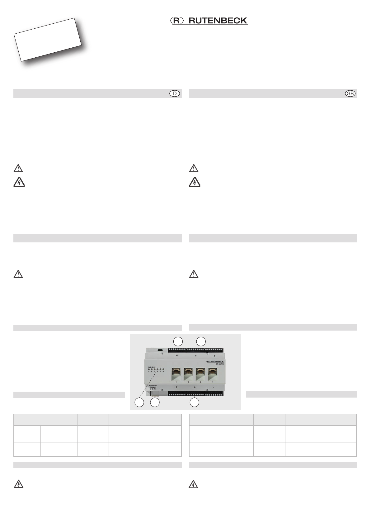
The device is an industrial Ethernet switch
according to DIN 43880 for installation in elec-
trical installation distributors. The 230 V connec-
tion is made via the detachable port (C) with 3
labelled plug-in contacts.
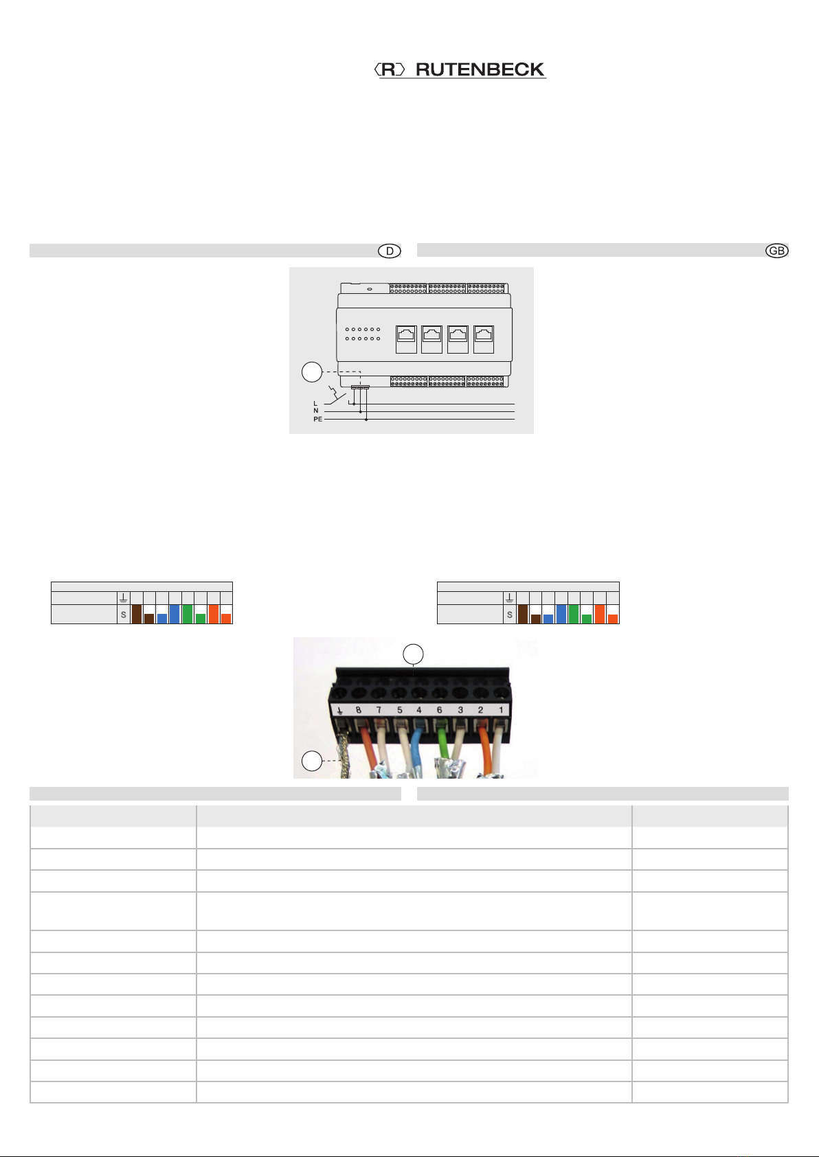
The REG-Switch SR permits the networking of a
total of 10 devices via the four integrated RJ45
bushes on the top side (B) and 2 x three terminal
block connections (A) in the sub-distribution area
that is covered at a later date.
LED
The lamps of the four RJ45 bushes and the LEDs
(D) have the following meaning:
Installation
Power supply connection
Danger to life! Isolate the power supply
prior to connection.
Follow the five safety rules according to DIN VDE 0105 when working
in and on electrical plants.
Sicherheitshinweise
Rechtliche Hinweise
Diese Anleitung enthält u.a. wichtige Anmerkungen und Warnungen,
deren Nichtbeachtung zu ernsthaften Personen- oder Anlageschäden
führen kann. Bitte lesen Sie die Anleitung vor Inbetriebnahme des REG-
Switch SR 10TX GB (im folgenden REG-Switch SR) aufmerksam durch.
Ordnungsgemäßer Transport, korrekte Lagerung und Installation sowie
sorgfältige Bedienung und Instandhaltung der Geräte sind entscheidend
für den sicheren Betrieb.
Spannungsversorgung
Der REG-Switch SR wurde sowohl für den Betrieb mit 230 V konzipiert.
Arbeiten am Versorgungsnetz dürfen nur von autorisiertem
Elektrofachpersonal ausgeführt werden!
Lebensgefahr durch elektrischen Strom! Bei allen Montagear-
beiten schalten Sie zunächst die Netzspannung frei.
Gehäusetemperatur
Wenn der REG-Switch SR bei Umgebungstemperaturen von über 45°C
betrieben wird, kann die Temperatur des Gehäuses mehr als 70°C
betragen. Das Gerät muss dann in einem abgeschlossenen Bereich
betrieben werden, der nur dem Service-Personal zugänglich ist oder
Benutzern, die über die Gründe dieser Einschränkung und über not-
wendige Vorkehrungen beim Betrieb über 45 °C informiert wurden.
Bestimmungsgemäßer Gebrauch
Der REG-Switch SR darf nur wie in der Anleitung beschrieben verwendet
werden. Es darf nur unbeschädigt und unter den angegebenen Umweltbe-
dingungen eingesetzt werden. Betreiben Sie das Gerät zu keinem ande-
ren Zweck und nur in Innenräumen.
Stellen Sie im Sinne der aktuellen Datenschutzrichtlinien sicher,
dass nur autorisiertes Personal Zugang zu dem Gerät bzw. dem
angeschlossenen Netzwerk hat.
Verwenden Sie nur zertifizierte Kabel. Andere Kabel können Fehl-
funktionen verursachen oder zur Zerstörung der Geräte führen.
Entsorgung
Das Gerät darf nicht über den normalen Hausmüll entsorgt werden – halten
Sie die nationalen und regionalen Vorschriften zur Entsorgung ein.
Allgemeines
Das Gerät ist ein industrieller Ethernet-Switch
nach DIN 43880 für den Einbau in Elektroinstalla-
tionsverteilern. Der 230 V Anschluss erfolgt über
die abziehbare Buchse (C) mit 3 gekennzeichne-
ten Steckkontakten.
Das REG-Switch SR erlaubt die Vernetzung von
insgesamt maximal 10 Geräten über vier integ-
rierte RJ45-Buchsen an der Oberseite (B) und
2 x drei Klemmblock-Anschlüsse (A) im später
abgedeckten Bereich der Unterverteilung.
LED
Die Beleuchtung der vier RJ45-Buchsen und die
LEDs (D) haben folgende Bedeutung:
Installation
Anschließen der Netzspannung
Lebensgefahr! Schalten Sie die Netzspannung vor dem
Anschließen frei.
Beachten Sie bei Arbeiten in und an elektrischen Anlagen die fünf
Sicherheitsregeln nach DIN VDE 0105:
Beleuchtung bzw. LED Zustand Bedeutung
RJ45
Buchse oben - grün
- blinkend
Datenverbindung ok
Datenverbindung/-verkehr
Link/Act
(5–10) Reihe links - grün
- blinkend
Datenverbindung ok
Datenverbindung/-verkehr
Technical Support
+49 - 23 55 - 82 111
Commercial Support
+49 - 23 55 - 82 137
kundenservice@rutenbeck.de
Lamp or LED State Meaning
RJ45
bush top - green
- flashing
data connection ok
data connection/traffic
Link/Act
(5–10) left row - green
- flashing
data connection ok
data connection/traffic
1A B
C AD
© Wilhelm Rutenbeck GmbH & Co. KG · 293 799 · Technische Änderungen vorbehalten/Subjected to technical changes · 293 799 · 235 105 05 · Rut059 · Stand/Status 10.17
Klagebach 33
D-58579 Schalksmühle
Telefon +49-(0) 23 55-82-0
Telefax +49-(0) 23 55-82-105
www.rutenbeck.de
[email protected]
REG-Switch SR 10TX GB
Schutzart Polyamid / Polyamide (PA 6/6.6), IP20 Protection Class
Betriebstemperatur -40 bis / to +45 °C Operating temperature
Lagertemperatur -40 bis / to +85 °C Storage temperature
Anschlüsse 6 schraubenlose Steckklemmen (abziehbar) / Screwless plug-in terminal (detachable)
4 RJ45 Buchsen / ports Connections
- Spezifikation 230 V Leitungsdurchmesser max. 2,5 mm2/ Cable diameter max. 2.5 mm2- 230 V Specification
- Spezifikation Ethernet IEEE 802.3U 1G-Base TX und / and 100Base-TX und / and 10Base-TX - Ethernet Specification
Spannungsversorgung 230 V 100–240 V / 50–60Hz / 100mA – 42mA Power supply 230 V
Leistungsaufnahme 10 W max. Power consumption
Luftfeuchtigkeit 5–95 % rHd nicht kondensierend / non-condensing Humidity
EMV EN 61000-6-2 / EN 55022 Klasse A / Class A EMC
Abmessungen H x B x T / H x W x D: 90 x 143 x 64 mm Dimensions
Gewicht 285 g Weight
Installation (Fortsetzung) Installation (Continued)
1 Freischalten
2 Gegen Wiedereinschalten sichern
3 Spannungsfreiheit allpolig feststellen
4 Erden und kurzschließen
5 Benachbarte unter Spannung stehende Teile
abdecken.
Beachten Sie das Anschlussbild 2 und schließen
Sie die Netzspannung (Leitungsdurchmesser
maximal 2,5mm2) mittels Klemmblock (C) ent-
sprechend an.
Um eine Beeinflussung des Netzwerks durch
Störungen/Veränderungen im Bereich der 230 V
Installation zu vermeiden, trennen Sie stets die
Spannungsversorgung aktiver Komponenten sowie der Datenendgeräte
(PC usw.) von denen anderer Verbraucher (z. B. Mikrowelle, Staubsauger).
Verwenden Sie eigene Stromkreise, indem Sie z.B. einen Leitungstrenn-
oder -schutzschalter einsetzen und ggf. einen geeigneten Überspan-
nungsschutz (C-Ableiter). Kennzeichnen Sie den Stromkreis sowie die
zugehörigen Steckdosen eindeutig, z.B. mit ‚EDV/DATA‘.
Anschließen des Netzwerk-Kabels an die Schraubklemmleiste
6 Ziehen Sie den 9-poligen Schraubklemmblock (A) ab und legen Sie die
Adern nach dem folgenden Farbcode auf.
VErhalten Sie die Paarschirmung und die
Verdrillung der Paare so lang wie möglich!
VVerdrillen Sie den Gesamtschirm (E)
und verwenden Sie ggf. eine
1-mm-Aderendhülse.
VBeachten Sie die gleiche Belegung im
Rangierfeld und an der Dose!
7 Setzen Sie den Klemmblock auf die Schraub-
klemme.
Technische Daten
1 Isolate
2 Secure against restart
3 Determine that the equipment is not live on
all poles
4 Earth and short-circuit
5 Cover or cordon off adjacent parts that are live.
Observe connection diagram 2 and connect the
power supply (max. cable diameter 2.5 mm2)
accordingly using the terminal block (C).
In order to prevent network impact caused by
disturbances/changes in the area of the 230 V
installation, always disconnect the power supply
to active components as well as data end devices (PC, etc.) from those to
other consumers (e.g. microwave, vacuum cleaner).
Always use independent circuits by utilising circuit breakers or circuit
switches and, where necessary, a suitable surge protection device
(C-conductor) for instance. Clearly label the circuit as well as the associat-
ed sockets, e.g. ‘EDP/DATA’.
Connection of network cable to the screw terminal block
6 Pull off the 9-pole terminal block (A) and connect the wires according
to the color code below.
VLeave the wire pair shielding and the wire
twist for as long as possible!
VTwist the shielding (E) and, if necessary,
use a 1 mm wire end sleeve.
VMake sure the wires are connected accord-
ing to the color code in the patch panel and
on the jack!
7 Put the terminal block on the screw terminal
block.
Technical Data
8 7 5 4 6 3 2 1
Farbcode
Klemme
Belegung
8 7 5 4 6 3 2 1
Colorcode
Terminal
Assignment
3A
E
230 V
2
C

Other Rutenbeck Switch manuals

Rutenbeck SV USB 50 Series User manual

Rutenbeck

Rutenbeck SV USB 50 Series User manual

Rutenbeck REG-Switch SR 10TX GB PoE User manual

Rutenbeck

Rutenbeck REG-Switch SR 10TX GB PoE User manual

Rutenbeck SR 5TX GB User manual

Rutenbeck

Rutenbeck SR 5TX GB User manual

Rutenbeck USB 4xUp User manual

Rutenbeck

Rutenbeck USB 4xUp User manual

Rutenbeck SR 2TX/2SC User manual

Rutenbeck

Rutenbeck SR 2TX/2SC User manual

Rutenbeck POF Switch REG User manual

Rutenbeck

Rutenbeck POF Switch REG User manual

Rutenbeck REG-Switch SR 5 User manual

Rutenbeck

Rutenbeck REG-Switch SR 5 User manual

Rutenbeck TCR IP 4 User manual

Rutenbeck

Rutenbeck TCR IP 4 User manual

Popular Switch manuals by other brands

D-Link DKVM-210H Quick installation guide

D-Link

D-Link DKVM-210H Quick installation guide

Asante IntraCore 35516 Series Setup guide

Asante

Asante IntraCore 35516 Series Setup guide

DANLERS CEFLA PIR DSIP Installation notes

DANLERS

DANLERS CEFLA PIR DSIP Installation notes

Arista 7500N Series quick start guide

Arista

Arista 7500N Series quick start guide

Pico Macom TSMS-16A Installation and operation manual

Pico Macom

Pico Macom TSMS-16A Installation and operation manual

ifs NS3702-24P-4S-V3 Quick installation guide

ifs

ifs NS3702-24P-4S-V3 Quick installation guide

Digitus 5-Port HDMI Switch manual

Digitus

Digitus 5-Port HDMI Switch manual

Jung A3181-1-01 operating instructions

Jung

Jung A3181-1-01 operating instructions

PCB Piezotronics 691B42 Installation and operating manual

PCB Piezotronics

PCB Piezotronics 691B42 Installation and operating manual

3Com SuperStack II 3C16690 user guide

3Com

3Com SuperStack II 3C16690 user guide

merten 6287 Series operating instructions

merten

merten 6287 Series operating instructions

Intel Express 210T user guide

Intel

Intel Express 210T user guide

AV Access 4KSW41-KVM-Pro user manual

AV Access

AV Access 4KSW41-KVM-Pro user manual

Intermatic ET2105C Installation and setup instructions

Intermatic

Intermatic ET2105C Installation and setup instructions

Rockwell Automation Allen-Bradley Stratix 5400 installation instructions

Rockwell Automation

Rockwell Automation Allen-Bradley Stratix 5400 installation instructions

ATEN Master View CS-1762 user manual

ATEN

ATEN Master View CS-1762 user manual

Allied Telesis AT-IE200-6GT-80 Command reference

Allied Telesis

Allied Telesis AT-IE200-6GT-80 Command reference

Omron D4NS - quick start guide

Omron

Omron D4NS - quick start guide

manuals.online logo
manuals.online logoBrands
  • About & Mission
  • Contact us
  • Privacy Policy
  • Terms and Conditions

Copyright 2025 Manuals.Online. All Rights Reserved.