StoneAge RPT-P8 User manual
RAPTOR
SELF ROTARY SWIVELS
(RPT-P8, RPT-MP9, RPT-M24)
USER MANUAL
PL 543 REV A
(01/2019)

2866-795-1586 • WWW.STONEAGETOOLS.COM
TABLE OF CONTENTS
This manual must be used in accordance with all applicable national laws. The manual shall be
regarded as a part of the machine and shall be kept for reference until the nal dismantling of the
machine, as dened by applicable national law(s). Updated manuals can be downloaded at:
https://www.stoneagetools.com/manuals
MANUFACTURER’S INFORMATION ...........................................................3
SPECIFICATIONS FOR ALL MODELS .....................................................3
KEY FEATURES FOR ALL MODELS .......................................................3
TOOL DESCRIPTION AND INTENDED USE ...............................................3
WARNING AND SAFETY INSTRUCTIONS .....................................................4
RAPTOR (RPT-P8, RPT-MP9, AND RPT-M24) .................................................5
TOOL CONFIGURATION...................................................................5
NOZZLE AND PLUG LOCATIONS .........................................................6
OPERATION ...............................................................................7
TROUBLESHOOTING .....................................................................8
TOOL SERVICE INFORMATION ...........................................................9
FLUID REPLACEMENT ....................................................................9
HIGH PRESSURE SEAL REPLACEMENT..................................................10
DISASSEMBLY ............................................................................11
ASSEMBLY ................................................................................13
PART NAMES/NUMBERS .................................................................17
MAINTENANCE KITS ......................................................................17
RAPTOR ACCESSORIES .......................................................................18
TERMS AND CONDITIONS AND WARRANTY .................................................20

3
866-795-1586 • WWW.STONEAGETOOLS.COM
MANUFACTURER’S INFORMATION
StoneAge Inc.
466 S. Skylane Drive
Durango, CO 81303, USA
Phone: 970-259-2869
Toll Free: 866-795-1586
www.stoneagetools.com
StoneAge Europe
Unit 2, Britannia Business Centre
Britannia Way
Malvern WR14 1GZ
United Kingdom
Phone: +44 (0) 1684 892065
DESCRIPTION OF EQUIPMENT
AND INTENDED USE
The Raptor self-rotating pipe cleaning tool is ideal
for cleaning process drains, totes, closed head
drums, water well screens, ducts and exhaust
stacks.
The Raptor handles ows up to 60 gpm to cut
through heavy deposits in pipes as small as 2.25
inches (57 mm) in diameter. Combined with a
centralizer, it cleans pipes as large as 12 inches (305
mm).
FEATURES
• Wide operating range- Better match your pump
capacity for more versatile cleaning capabilities
of heavy to light deposits with one tool.
• Multiple head options- Same tool pairs with
multiple heads, saving the cost of a purchasing
a second specialized tool.
• Pulling ring option available- Clean vertical or
extra long horizontal lines, a feature not widely
available on similar tools.
• Two speed ranges- Maximize cleaning by
choosing slower speeds for hard to clean or
plugged pipes, and faster speeds for polishing
easy to clean pipes with a single tool.
• Jetting options to match the work required-
Same tool can be re-jetted to match a variety
of cleaning applications — great for when you
need more pulling force vs. forward hitting
power.
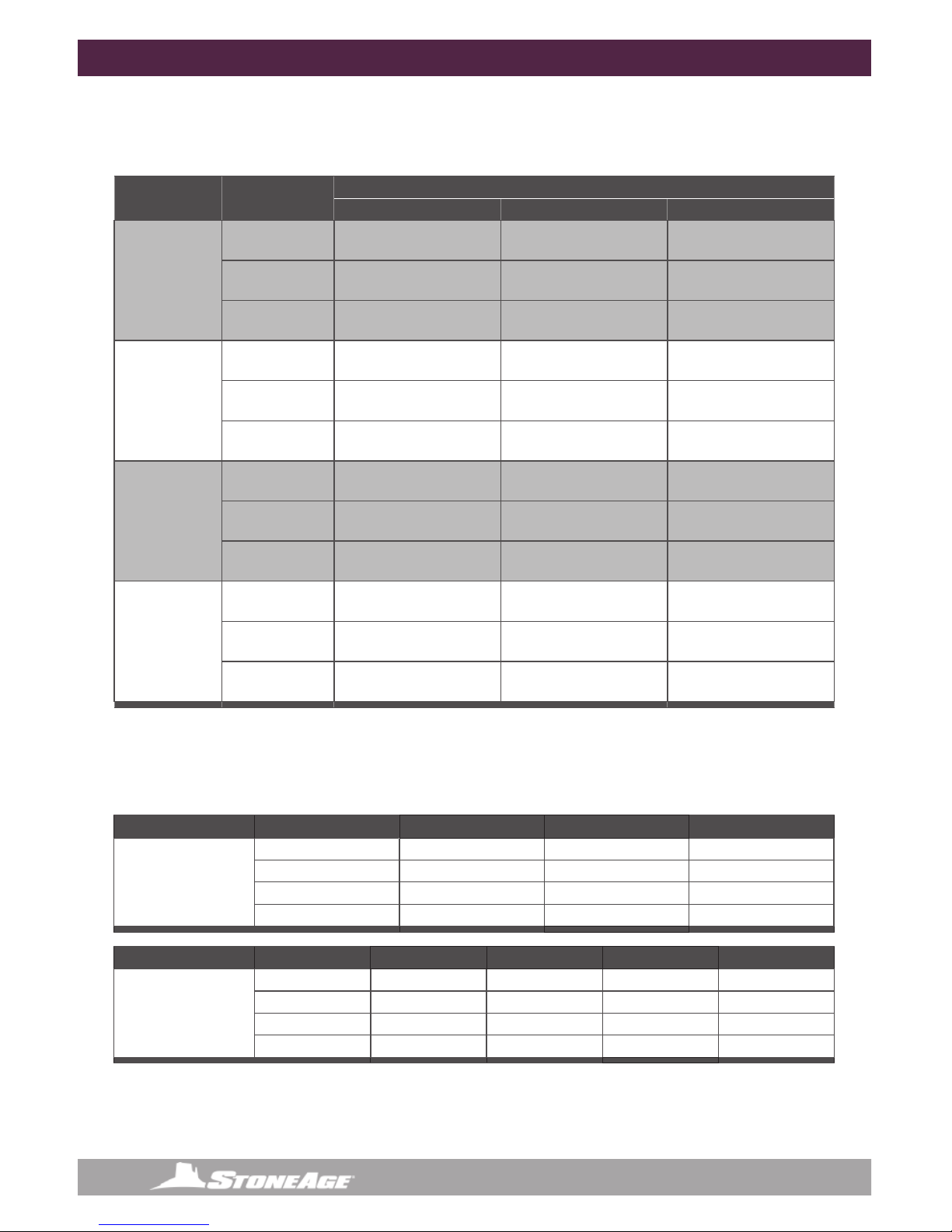
Raptor Model Specifications
Model RPT-P8 RPT-MP9/RPT-M24
Pressure Range 2–15k psi (140–1000 bar) 2–22k psi (140–1500 bar)
Flow Range 10–60 gpm (38–227 l/min) 10–60 gpm (38–227 l/min)
Flow Coefcient 2.3 Cv 2.3 Cv
Rotation Speed 15-60 rpm (Slow Fluid)
50-250 rpm (Fast Fluid)
15-60 rpm (Slow Fluid)
50-250 rpm (Fast Fluid)
Inlet Connection 1/2 NPT 9/16 MP, M24
Port Size 1/8 NPT (P2), 1/4 NPT (P4) 1/8 NPT (P2), 1/4 NPT (P4)
Extension Port Size 1/4 NPT (P4) 1/4 NPT (P4)
Nozzle Type AP2, AP4, APF4 AP2, AP4, APF4
Plug GP 025-P2SS GP 025-P2SS
Extension Plug GP 025-P4SS GP 025-P4SS
Swivel Diameter 2 in. (51 mm) 2 in. (51 mm)
Swivel Length 9.5 in. (240 mm) 9.5 in. (240 mm)
Swivel Weight 4.2 lb (1.9 kg) 4.2 lb (1.9 kg)
Head Diameter 2.0-2.5in (51-64mm) 2.0-2.5in (51-64mm)
Head Weight 1.1–2.4 lb (0.5–1.1 kg) 1.1–2.4 lb (0.5–1.1 kg)
Maximum Water Temperature 160 ºF (70 ºC) 160 ºF (70 ºC)

4866-795-1586 • WWW.STONEAGETOOLS.COM
WARNING AND SAFETY INSTRUCTIONS
WARNING
Raptor Models can turn around in large pipes and come back at the operator at a high rate of
speed. If cleaning larger pipes, a rigid “stinger” should be used between the hose and the tool. It is
recommended that the rigid length of the tool including hose end is 1-1/2 times the inside diameter of
the pipe being cleaned (see below).
Make sure there is an operator controlled dump in the system, operated by the person closest to the
cleaning job. Flush out the high pressure hoses before connecting the Raptor. It is recommended that
the hose be marked a few feet from the end with a piece of tape so the operator knows when to stop
when retracting the tool. Position the tool in the pipe opening. Close the dump and slowly bring up to
pressure the rst time to make sure no nozzles are plugged and the jet thrust is correct. The Raptor
should begin to slowly rotate. Once operating pressure is reached, feed the tool into the pipe to begin
the cleaning job. Allow the jets time to do their work by feeding the hose out at a controlled rate. The
StoneAge ABX-500 Hose Control Device can be used to achieve consistent feed rates for pipe cleaning.
When the work is complete and the tool is disconnected from the hose, blow out all water to prolong
the life of the tool. A small amount of oil can be blown into the tool as well as an added measure to
maximize tool life.
It is strongly recommended to use a backout prevention device. Please see the “Accessories”
section of this manual for a list of backout preventers available through StoneAge Tools.
DANGER
Operations with this equipment can be potentially hazardous. Caution must be exercised prior to and
during machine and water jet tool use. Please read and follow all of these instructions, in addition to
the guidelines in the WJTA Recommended Practices handbook, available online at
www.wjta.org.
Deviating from safety instructions and recommended practices can lead to severe injury and/or death.
Rigid
Stinger
IMPROPER USE:
Raptor will turn around in
large diameter pipe
VERY DANGEROUS!
PROPER USE:
Raptor with rigid “stinger”
to prevent turnaround.
1-1/2 times
pipe ID
Rigid
Stinger

5
866-795-1586 • WWW.STONEAGETOOLS.COM
TOOL CONFIGURATIONS
HEAD SELECTION
There are two standard head congurations for Raptor tools. Custom heads are available on request. The
correct head specication is based on the pressure and ow of the pump and the required port size.
The following table lists head selection approximations of common jetting scenarios.
See the next page for Head and Swivel combinations based on common pressures and ows.
7-PORT
1 @ 15º, 2 @ 45º, 1 @ 80º, 1 @ 100º,
2 @ 135º
45º
45º
15º
100º
135º
135º
80º
6-PORT
2 @ 45º, 1 @ 80º, 1 @ 100º,
2 @ 135º
45º
45º
100º
135º
135º
80º
SWIVEL SELECTION
There are six Raptor swivel options available. The correct swivel is selected based on the maximum working
pressure, inlet connection and required rotation speed.
Maximum Pressure Inlet Connection Swivel Part ID Based on Rotation Speed
SLOW (15-60 rpm) FAST (50-250 rpm)
15k psi
1000 bar 1/2 NPT Female RPT-P8-S RPT-P8-F
22k psi
1500 bar
M24 Female RPT-M24-S RPT-M24-F
9/16 MP Female RPT-MP9-S RPT-MP9-F
RAPTOR TOOL CONFIGURATION
Nozzle HeadSwivelHose Adapter.
if required
6866-795-1586 • WWW.STONEAGETOOLS.COM
NOZZLES AND PLUG LOCATIONS
Raptor tool heads can be congured differently depending on the application. The thrust of the jets can be
used to pull the tool through a pipe. Little or no pull is needed for cleaning vertically downward, but more pull is
needed if cleaning horizontally or climbing upward.
The table below shows suitable nozzle/plug congurations for the Raptor tools.
Head Style 45º Port 80º Port 100º Port 135º Ports
6 Port
2 x Nozzle 1 x Nozzle 1 x Nozzle 2 x Nozzle
2 x Plug 1 x Nozzle 1 x Nozzle 2 x Nozzle
2 x Plug 1 x Nozzle 1 x Nozzle 2 x Plug
2 x Plug 1 x Plug 1 x Plug 2 x Nozzle
Head Style 15º Port 45º Port 80º Port 100º Port 135º Ports
7 Port
1 x Nozzle 2 x Nozzle 1 x Nozzle 1 x Nozzle 2 x Nozzle
1 x Nozzle 2 x Plug 1 x Nozzle 1 x Nozzle 2 x Nozzle
1 x Nozzle 2 x Nozzle 1 x Plug 1 x Plug 2 x Nozzle
1 x Nozzle 2 x Plug 1 x Plug 1 x Plug 2 x Nozzle
The nozzle sizes should be selected based on proportioning the total ow rate between the forward and
backward jets to achieve the pulling force needed, but still applying enough power to the material being
removed ahead of the tool. Use the StoneAge Jetting App to determine the nozzle sizes:
http://jetting.stoneagetools.com
NOZZLE AND PLUG LOCATIONS
RAPTOR TOOL CONFIGURATIONS CONTINUED
PLEASE NOTE: The following table lists head selection approximations of common jetting scenarios for Raptor
swivels:
Pressure Flow Head Type
6 X P2 PORTS 2” Ø 7 X P2 PORTS 2” Ø 6 X P4 PORTS 2.5” Ø
5k psi
350 bar
10–23 gpm
38–87 l/min RPT 043-P2-6-R30 RPT 043-P2-7-R30 RPT 044-P4-6-R30
16–38 gpm
60 –140 l/min RPT 043-P2-6-R18 RPT 043-P2-7-R18 RPT 044-P4-6-R18
25–60 gpm
95–230 l/min RPT 043-P2-6-R11 RPT 043-P2-7-R11 RPT 044-P4-6-R11
10k psi
700 bar
10–18 gpm
38–68 l/min RPT 043-P2-6-R30 RPT 043-P2-7-R30 RPT 044-P4-6-R30
15–31 gpm
57–120 l/min RPT 043-P2-6-R18 RPT 043-P2-7-R18 RPT 044-P4-6-R18
25–51 gpm
95 –190 l/min RPT 043-P2-6-R11 RPT 043-P2-7-R11 RPT 044-P4-6-R11
15k psi
1000 bar
10–17 gpm
38–64 l/min RPT 043-P2-6-R30 RPT 043-P2-7-R30 RPT 044-P4-6-R30
16–28 gpm
60 –110 l/m in RPT 043-P2-6-R18 RPT 043-P2-7-R18 RPT 044-P4-6-R18
26–47 gpm
98 –180 l/min RPT 043-P2-6-R11 RPT 043-P2-7-R11 RPT 044-P4-6-R11
22k psi
1500 bar
10–16 gpm
38–60 l/min RPT 043-P2-6-R30 RPT 043-P2-7-R30 RPT 044-P4-6-R30
17–26 gpm
64–100 l/min RPT 043-P2-6-R18 RPT 043-P2-7-R18 RPT 044-P4-6-R18
27–43 gpm
100–160 l/min RPT 043-P2-6-R11 RPT 043-P2-7-R11 RPT 044-P4-6-R11

7
866-795-1586 • WWW.STONEAGETOOLS.COM
OPERATION
OPERATION:
• Make sure there is an operator controlled dump in the system, operated by the person closest to
the cleaning job.
• Flush out the high pressure hoses before connecting Raptor to hose end or stinger to eliminate
debris.
• When cleaning a pipe, it is recommended that the hose be marked a few feet from the end with a
piece of tape so the operator knows when to stop on the way back out.
• When cleaning a pipe, a stinger is recommended; a stinger is a rigid piece of pipe or tubing used
between the end of the hose and the nozzle. It is typically 2 feet in length, and is primarily a safety
device for hand ex lancing. This is illustrated on the “Warning and Safety Instructions” page of
this manual.
• Position the Raptor in a tube or the pipe while the pressure is being set. The high pressure seal
may leak initially; it should stop when pressure is increased and rotation begins.
• Close the dump and slowly bring up to pressure the rst time, to make sure no nozzles are
plugged and that the jet thrust is correct. The swivel should begin to slowly rotate.
• Once operating pressure is reached, feed the tool into the tube or pipe to begin the cleaning job.
• When using rotating heads in plugged tubes, the Raptor must not be forced into the deposit, as
this may stop the rotation of the tool and impede the cutting ability. When the Raptor contacts
the deposit, allow it to cut away the material and advance at it’s own rate. If it stops advancing,
pull back slightly on the hose to pull the head slightly away from the deposit, in case it is being
stopped from rotating by the deposit. This also allows the angled jets to attack the deposit at
different places.
• When polishing tubes with scale, it is possible to allow the tool to pass through the tube at very
fast rates; unless the deposit is very easy to remove, this will not completely remove the scale.
• The operator needs to be trained to feed the Raptor through the tube at a rate sufcient to clean
the tube.
• Once the work is complete and the Raptor is disconnected from the hose, blow out all water to
prolong the life of the tool. A small amount of oil can be blown into the inlet nut as well.
8866-795-1586 • WWW.STONEAGETOOLS.COM
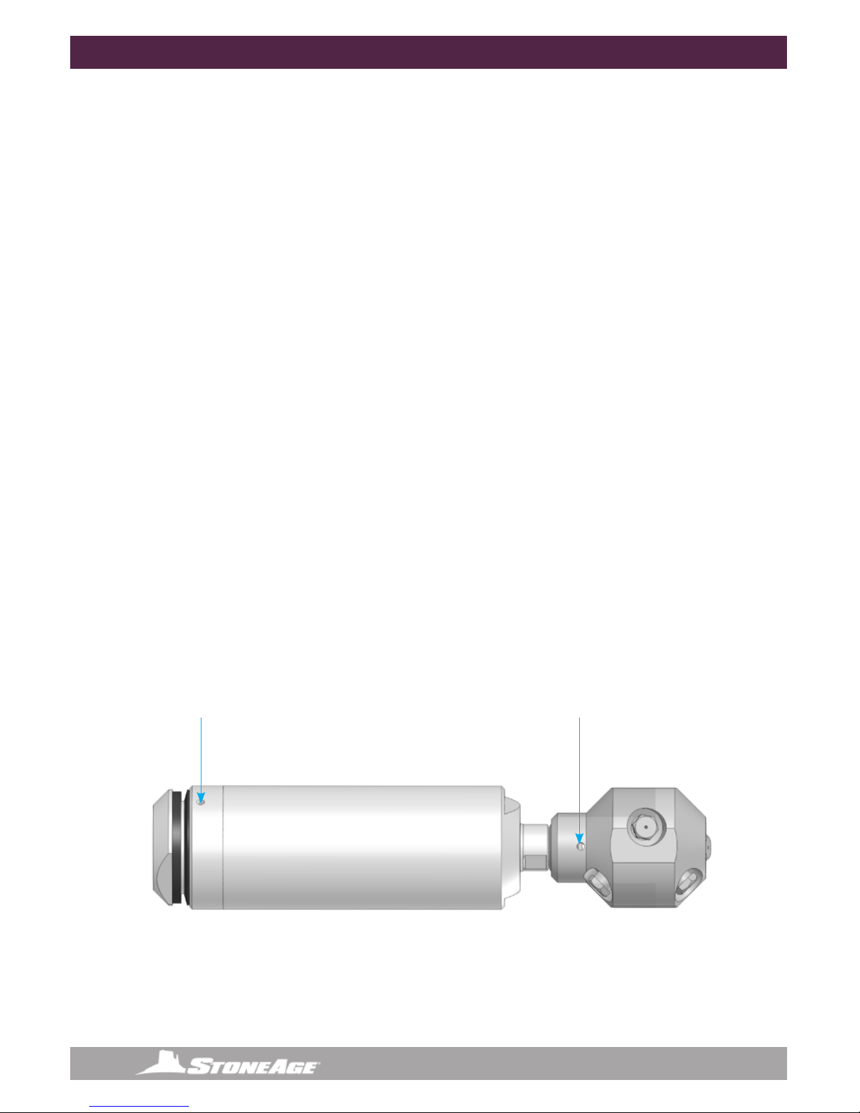
TROUBLESHOOTING
HIGH-PRESSURE WATER SEALS LEAK:
• The high pressure seal may leak initially at lower pressures, but should pop closed as pressure
is increased. A continuous leak at operating pressure from the weep holes indicates the need
to replace the HP Seal and Seat. HP Seals wearing out too quickly can be an indication that the
shaft bore is worn, the HP Seat in the seal assembly is installed upside-down, or the tool is over
spinning. Over spinning is caused by low or contaminated viscous uid, water in the uid chamber
(replace shaft seals), or too much jet torque. Relling the viscous uid every 40-80 hours of
operation is important for proper speed control. Only use StoneAge recommended viscous uid.
SEALS WEAR OUT TOO QUICKLY:
• The tool must be disassembled and inspected. The carbide seat should be checked for being
installed in the right direction, and it should not have any chips or erosion marks on it. The bore
of the shaft where the high pressure seal is located should be checked for grooving. If it is worn
larger than .508”, the shaft will need to be replaced.
HEAD WILL NOT ROTATE:
• First try rotating head by hand and see if it feels rough or gritty to turn. If it does, the tool must
be disassembled and repaired. If the head starts to rotate but as pressure is increased it slows
down and stops, it likely has bad bearings. If the tool feels okay, check to see if any nozzles are
plugged; even if a nozzle is only partially blocked it can keep the head from rotating. Nozzles must
be removed from the head to properly clean them; it does not do any good to poke the material
plugging the nozzle back into the head, as it will just replug a nozzle. If none of these are the
problem, the jets are too small or the head offset is not correct; refer to the above description
about the head offset and double check the nozzle sizes to make sure they are correct for the
expected ow rate.
HEAD SPINS TOO FAST:
• A signicant increase in rotation speed means that the speed control mechanism in the tool has
lost functionality. This can be a result of viscous uid loss or uid contamination. Operation of
the tool in this state can cause damage to other components and accelerated wear of the high
pressure seal. If this occurs, the rst step is to ush the tool with new viscous uid as shown in
the “Lubricant Replacement” instructions in this manual.
LEAKAGE FROM HERE
INDICATES WORN O-RINGS
LEAKAGE FROM HERE
INDICATES A WORN SEAL
9
866-795-1586 • WWW.STONEAGETOOLS.COM
TROUBLESHOOTING TOOL SERVICE INFORMATION
TOOL SERVICE
***Product training and proper tools are required to service this nozzle.
If you are uncomfortable performing the service, send in or bring the tool to your authorized dealer.
StoneAge provides maintenance videos for the Raptor models online.
https://www.youtube.com/watch?v=U2ABW4lcDkE
The use of a bench vice and an arbor press is recommended. Take care throughout the entire
procedure to keep the internals clean and free from grit, lint, and contamination. Failure to do so could
result in premature failure after service.
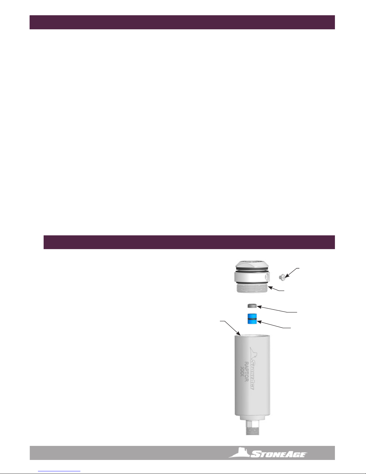
LUBRICANT FILL INSTRUCTIONS
The most important item in maintaining this swivel
is keeping the tool full of viscous uid, which
provides lubrication and speed control. The viscous
uid should be checked when the tool begins to
run faster than usual, and during high pressure seal
replacement. Clamp the ats of the Raptor body in
a vice.
1. Remove the BJ 026 Port Plug from the Inlet Nut
2. With an adjustable end wrench, remove and
retain the nut assembly. Remove and retain the
High Pressure Seal and Carbide.
3. If the uid appears contaminated, it should be
drained and replaced
4. Rell with Viscous uid to covering bearing.
5. Install the High Pressure Seal and Carbide Seat.
6. Install the Inlet Nut onto the body with an
adjustable end wrench.
7. Install the Port Plug.
LUBRICANT REPLACEMENT
BJ 026
Port Plug
Fill with
viscous uid
to cover
bearing
Figure 1: Lubricant Flush
LIST OF TOOLS:
• Bench Vice (recommended)
• Arbor Press (recommended)
• RPT 612 Kit Contains; RPT 105 Seal Press tool
• 18” Adjustable Wrench (such as Crescent®
C718 Automatic Adjustable Pipe Wrench)
• Small size at-head screw driver
• Medium size at-head screw driver
• Pick
• Ball point pen
• 9/64” Hex Wrench
• Snap Ring Pliers
LIST OF MATERIALS:
• Clean lint free rags or blue shop towels
• BJ 048-F Viscous Fluid
• BJ 048-S Viscous Fluid will help slow the
rotation of the Swivel if desired
• Anti-Seize -
StoneAge Part Number GP 043 Blue Goop
• Lithium Soap Grease –
StoneAge Part Number GP 048 Grease
• P-80®Grip-IT Lubricant
Blue Goop® is a registered trademark of the Swagelock®Corporation.
P-80®Grip-IT Lubricant is a registered trademark of the International Products Corporation.
BJ 012-TRO
H.P. Seal and
O-Ring
BJ 011-C
Carbide Seat
RPT 002-P8 or
MP9 or M24x1.5
Inlet Nut
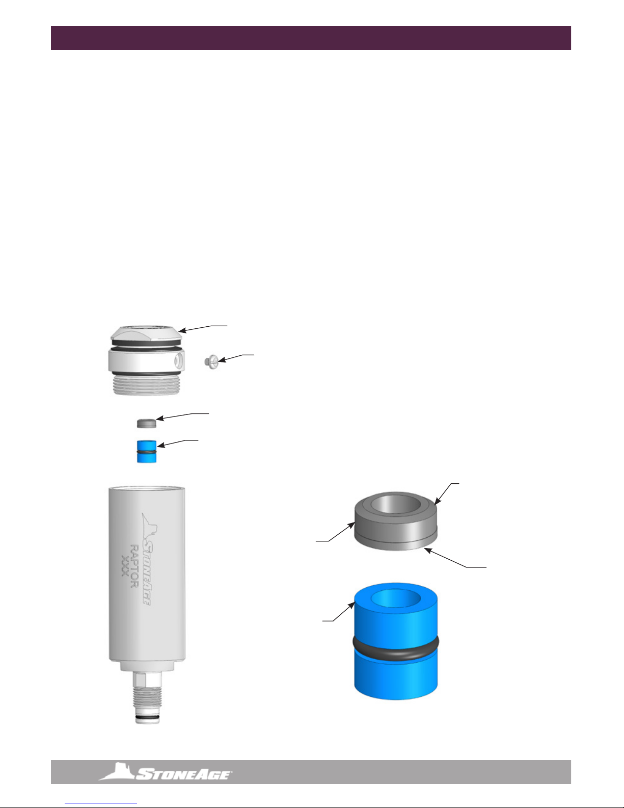
10 866-795-1586 • WWW.STONEAGETOOLS.COM
Chamfered face of
carbide seat
Flat face of
carbide seat
BJ 012-TRO
H.P. Seal and
O-Ring
BJ 012-TRO
H.P. Seal and
O-Ring
BJ 011-C
Carbide Seat
BJ 011-C
Carbide Seat
BJ 026
Port Plug
RPT 002-P8 or MP9 or
M24x1.5 Inlet Nut
Figure 2:
Figure 3: High Pressure
Seal Subassembly
HIGH PRESSURE SEAL REPLACEMENT
TO REPLACE THE HIGH PRESSURE SEAL:
1. Remove the Port Plug (BJ 026).
2. Unscrew the Inlet Nut (RPT 002-P8, MP9 or M24x1.5) from the Body.
3. Pull out the Seat (BJ 011-C) and H.P. Seal (BJ 012-TRO) from the bore of Shaft.
4. Inspect the bore of the Shaft; if it is badly grooved it should be replaced.
5. Inspect the face of the Inlet Nut where the Seat makes contact; if it is pitted or dented, it should be
faced or replaced.
6. Check the viscous uid level and condition; if the uid appears badly contaminated it should be
replaced. Otherwise add uid to cover the Bearing.
7. Apply grease to a new H.P. Seal and install into bore of Shaft. Do not push it all the way in.
8. Place a new Seat (BJ 011-C) on top of H.P. Seal; the at face of the Seat goes against the seal (see
detail). Push it in just far enough so that it will stay in the bore.
9. Apply anti-seize to threads of Inlet Nut and thread into Body; make sure the Seat stays centered in
bore of Shaft. Tighten to 50 ft-lb.
10. Install the Port Plug.
DISASSEMBLY
11
866-795-1586 • WWW.STONEAGETOOLS.COM
RPT 002-P8
or MP9
or M24x1.5
Inlet Nut
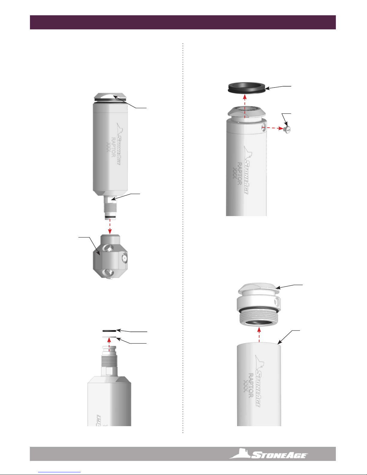
DISASSEMBLY
DISASSEMBLY
1. Locate the ats on the Head and tighten
them in a vice, so that the Inlet Nut end of
the Raptor is facing up.
2. Slide an adjustable wrench onto the Collar
ats and loosen the Head from the Body.
Figure 4: For Steps 1-2
Figure 5: For Steps 3-5 Figure 7: For Step 8
Figure 6: For Steps 6-7
Shaft Flats
Inlet Nut
Flats
Head Flats
in the vice
3. Remove the Raptor from the vice, ip it over
and using a pick, remove the MJ 016 O-Ring
from the Shaft Assembly.
4. Remove the BC 031 Backup Ring.
MJ 016
O-Ring
BC 031
Backup Ring
5. Remove the BJ 021-S Weep Seal with a pick.
6. Remove the BJ 026 Port Plug with a small
at-head screw driver.
7. With and adjustable end wrench remove the
Inlet Nut.
RPT 003
Body
BJ 026
Port Plug
BJ 021-S
Weep Seal

12 866-795-1586 • WWW.STONEAGETOOLS.COM
8. With a pick remove the Carbide Seat and
High Pressure Seal from inside of the Shaft.
Figure 8: For Step 8
Figure 9: For Steps 9-10
9. With a pick remove the remove the O-Ring
from around the Inlet Nut.
10. Gently pry the Shaft Seal out of the Inlet
Nut with a common screwdriver.
11. Slide the Shaft Assembly out of the Body.
12. Remove all the Bearings from the Shaft
DISASSEMBLY / ASSEMBLYDISASSEMBLY
RPT 008
O-Ring
RPT 010
Dual Lip Seal
RPT 003
Body
RPT 001
Shaft
CJSW 009
Bearings
CJ 009
Bearing
Figure 10: For Steps 11-12
TECH TIP: A bearing separator/puller set
and an arbor press will help with the bearing
removal from the Shaft.
BJ 012-TRO
H.P. Seal
BJ 011-C
Carbide Seat
13
866-795-1586 • WWW.STONEAGETOOLS.COM
13. Remove the SL 010 Shaft Seal from the
RPT 003 Body with a pick or Snap Ring
Pliers.
Figure 11: For Steps 13
DISASSEMBLY COMPLETE
RPT 003
Body
NOTICE
Before reassembly of the tool
Wash all parts in solvent and blow dry
and
Inspect wear items, (High Pressure Seal
Assembly, O-Rings, and Port Plug.)
See the “Maintenance Kits” section of this
manual for a complete list of Service, Overhaul,
and, Tool kits.
DISASSEMBLY / ASSEMBLY
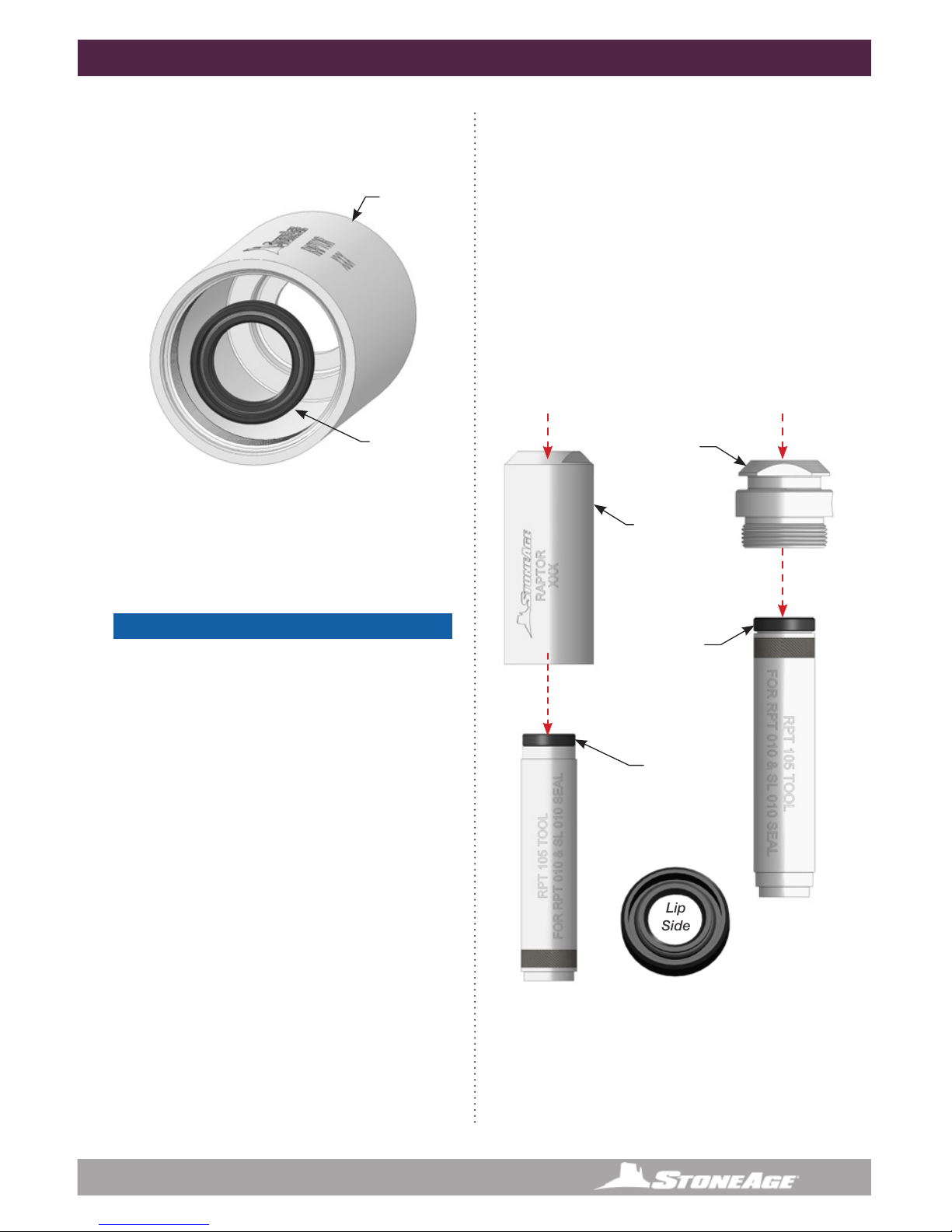
SL 010
Shaft Seal
Figure 12: For Steps 1-3
RPT 002
Inlet Nut
RPT 003
Body
PRESS PRESS
ASSEMBLY
1. Lubricate the SL 010 and RPT 010 Shaft
Seals with P-80®Grip-IT Lubricant or
equivalent.
2. Put the RPT 010 Shaft Seal on the RPT 105
tool (LIP SIDE DOWN) and using an Arbor
press, press the seal into the Body.
3. Put the SL 010 Shaft Seal on the RPT 105
tool (LIP SIDE DOWN) and using an Arbor
press, press the seal into the Body.
Lip
Side
SL 010
Shaft Seal
(Lip side DOWN)
RPT 010
Shaft Seal
(Lip side DOWN)

14 866-795-1586 • WWW.STONEAGETOOLS.COM
ASSEMBLY
4. Press clean or new bearings onto shaft in
the order shown below.
RPT 001
Shaft
Shaft
Assembly
Grease
Seal at
this end
Fill with
Viscous
uid
Turn Shaft
to remove
bubbles in
uid
RPT 003
Body
CJSW 009
Bearings
CJ 009
Bearing
Figure 13: For Step 4
Figure 14: For Steps 5-6
5. Grease the Shaft Seal in the Body
generously.
6. Slide the Shaft Assembly into the Body.
Figure 15: For Steps 7-8
Figure 16: For Steps 7-8
BJ 012-TRO
H.P. Seal
BJ 011-C
Carbide Seat
7. Grease H.P. Seal and insert into the Shaft.
Push down enough to leave 1/16” recess
for the Carbide Seat.
8. The Carbide Seat should be inserted with
the at side down and nestle onto the H.P.
Seal with the chamfer side facing up.
Chamfered
face of
carbide
seat
Flat face
of carbide
seat
9. Fill tool with BJ 048-Fast or Slow viscous
uid. Turn shaft to remove bubbles in uid
and repeat until tool is completely full of
viscous uid.

15
866-795-1586 • WWW.STONEAGETOOLS.COM
ASSEMBLY
Figure 16: For Steps 11-12 Figure 19: For Steps 14-15
Figure 17: For Step 13Figure 15: For Step 10
10. Place O-Ring at base of Inlet Nut threads.
RPT 008
O-Ring
Inlet Nut
Assembly
Anti-seize
11. Apply Anti-seize to the threads and screw
the Inlet Nut into the Body
12. Tighten down with an adjustable end
wrench to 50 ft lbs.
13. Replace the Port Plug and Weep Seal.
BJ 021-S
Weep Seal
BJ 026
Port Plug
14. Flip the Raptor in the vice and clamp
down on the Inlet Nut ats.
15. Slip the Backup O-Ring onto the Shaft rst
with the at side down and concave side
up to receive the regular O-Ring.
Concave
Side
Flat
Side
Regular
O-Ring
MJ 016
O-Ring
BC 031
Backup
Ring

16 866-795-1586 • WWW.STONEAGETOOLS.COM
ASSEMBLY
16. Grease the O-Rings
17. Apply Anti-seize to the threads and screw
the head onto the tool.
18. Place the ats on the Head in a vice and
Tighten from the Shaft ats with an ad-
justable wrench.
Figure 20: For Steps 16-18
Lithium
Soap
Grease
Anti-Seize
Head
Flats
Shaft
Flats

17
866-795-1586 • WWW.STONEAGETOOLS.COM
MAINTENANCE KITS
KITS PART NUMBER OVERVIEW
RPT 600-F or S SERVICE KIT
1 BJ 011-C Carbide Seat
1 BJ 012-TRO H.P. Seal & O-Ring
1 BJ 026 Port Plug
1 BJ 048-F Fast Viscous Fluid-6oz (-F)
1 BJ 048-S Slow Viscous Fluid-6oz (-S)
1 PL 543 Raptor User Manual
RPT 602 SEAL KIT
1 BJ 072 O-Ring
1 GO 123 O-Ring
1 RJ 011-KC Carbide Seat
1 RJ 012-KTO H.P. Seal & O-Ring
RPT 610-F or S OVERHAUL KIT
1 BJ 011-C Carbide Seat
1 BJ 012-TRO H.P. Seal & O-Ring
1 BJ 021-S Weep Seal
1 BJ 026 Port Plug
1 BJ 048-F Fast Viscous Fluid-6oz (-F)
1 BJ 048-S Slow Viscous Fluid-6oz (-S)
2 CJ 009 Bearing
1 CJSW 009 Bearing
1 MJ 016 O-Ring
1 PL 543 Raptor User Manual
1 RPT 008 O-Ring
1 RPT 010 Dual Lip Seal
1 RPT 031 Back-up O-Ring
1 SL 010 Large Seal
RPT 612 TOOL KIT
1 RPT 105 Double End Seal Press Tool
1 RPT 064 Raptor Fill Tube
1 RPT 106 Shaft Wrench
CJ 009
Bearing
BJ 011-C
Carbide Seat
BJ 012-TRO
H.P. Seal and
O-Ring
RPT 010
Seal
RPT 008
O-Ring
RPT 002
Inlet Nut
BJ 026
Port Plug
BJ 021-S
Weep Seal
SL 010
Seal
MJ 016
O-Ring
RPT 031
Back-up
O-Ring
RPT 001
Shaft
RPT 003
Body
CJSW 009
Bearings
RPT 043-XX
Head with
AP2-XXX
Nozzles (5)
OR
RPT 044-XX
Head with
AP4-XXX
Nozzles (5)
18 866-795-1586 • WWW.STONEAGETOOLS.COM
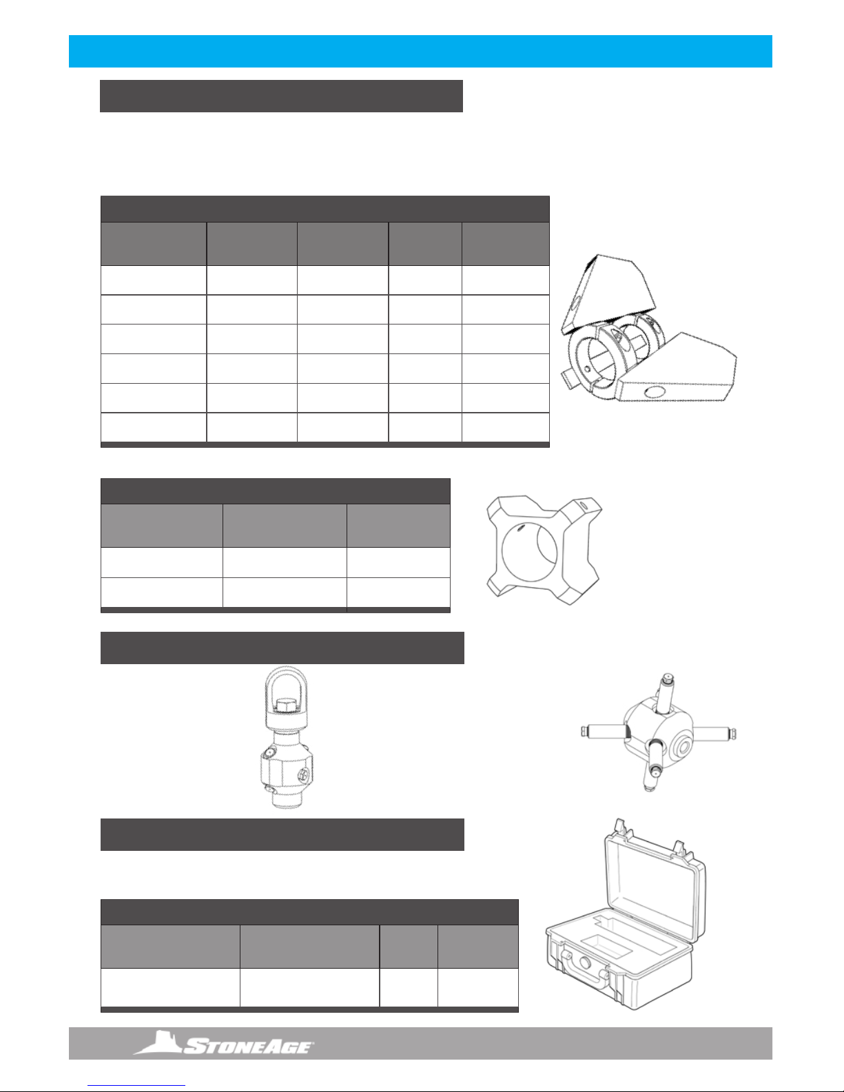
ACCESSORIES
A centralizer helps to protect the tool as it passes through the pipe and balances jet standoff distance for
more consistent cleaning. In cases where pipe size is more than 1.5 times the diameter of the tool, a central-
izer is an important safety device, preventing the tool from turning around and thrusting backwards out of the
pipe. Two types of centralizers are available for Raptor tools. See the tables below.
CENTRALIZER OPTIONS
STORAGE
HEAD ACCESSORIES
PLASTIC CENTRALIZER WITH SET SCREWS
Pipe Size Centralizer
(Complete) Weight
3 in. 76 mm RPT 075-3 0.3 lb 0.1 kg
4.5 in. 114 mm RPT 075-4.5 0.5 lb 0.2 kg
CENTRALIZER WITH SKIDS AND COLLARS
Pipe Size Centralizer
(Complete) Weight Collar* Skid**
4 in. 100 mm RPT 070-4 1.4 lb 0.6 kg RPT 070.1 RJ 070.2-4
5 in. 127 mm RPT 070-5 1.6 lb 0.7 kg RPT 070.1 RJ 070.2-5
6 in. 152 mm RPT 070-6 1.9 lb 0.9 kg RPT 070.1 RJ 070.2-6
8 in. 203 mm RPT 070-8 2.2 lb 1.0 kg RPT 070.1 RJ 070.2-8
10 in. 254 mm RPT 070-10 3.7 lb 1.7 kg RPT 070.1 RJ 070.2-10
12 in. 305 mm RPT 070-12 4.0 lb 1.8 kg RPT 070.1 RJ 070.2-12
*Set of 2 collars **Set of 3 skids with 6 screws
CARRYING CASE
Exterior Dimensions
(L x W x D)
Interior Dimensions
(L x W x D) Color Case Part
ID
11.6 x 8.3 x 3.8 in.
29.6 x 21.2 x 9.6 cm
10.5 x 6.0 x 3.2 in.
26.8 x 15.3 x 8.0 cm Black RPT 080
A PelicanTM brand protection/carrying case with custom cut
foam insert is available for Raptor tool models.
PULLING RING RPT 045
A pulling ring is
available for 6-port
Raptor heads.
EXTENSION NIPPLES
Extension nipples up to 12 inches
are available for use with 6-port P4
Raptor heads. A complete list of
Nozzles and Extensions is available
in the StoneAge Tools Waterblast
catalog and website.

19
866-795-1586 • WWW.STONEAGETOOLS.COM
ACCESSORIES ACCESSORIES
SAFETY OPTIONS
MAINTENANCE RESOURCES
Backout preventers increase operator safety by keeping the tool from backing out of the pipe. Several options are
available including xtures for small diameter pipes, pipes with various ange bolt circle diameters, and adapters
for pipes with no-ange entry.
BACKOUT PREVENTERS
Pipe Size Hose OD Backout
Preventer Description Weight
2–6 in.
51–150 mm
0.3–0.7 in.
8–18 mm BJ 305* Backout preventer for small pipes 5.6 lb
2.5 kg
4–8 in.
100–200 mm
0.3–1.5 in.
8–38 mm BJ 310 Backout preventer for small to medium pipes 7.6 l b
3.4 kg
5–17 in.
130–430 mm
0.3–1.5 in.
8–38 mm BJ 320 Backout preventer for medium to large pipes 6.3 lb
2.9 kg
15–36 in.
380–910 mm N/A BJ 325 Extension kit for BJ 320 backout preventer 8.5 lb
3.6 kg
8–36 in.
130 –910 mm N/A BJ 340 No-ange kit for BJ 320 backout preventer 17 lb
7.7 kg
*Securing device not supplied
BJ 305 BJ 310 BJ 320 BJ 320
shown with BJ 325
extension kit and BJ 340
No-ange attachment kit
KITS
Rotation
Speed Service Kit Seal Kit Overhaul Kit Tool Kit Lubricant Manual
Fast RPT 600-F RPT 602 RPT 610-F RPT 612 BJ 048-F PL 543
Slow RPT 600-S RPT 602 RPT 610-S RPT 612 BJ 048-S PL 543
Complete part breakdowns of each kit are available in the “Maintenance Kits” sections in this manual.
Kit components and tool maintenance/assembly videos are also available on our website:
WWW.STONEAGETOOLS.COM
For questions or help with a specic application, conguration or tool repairs, please contact StoneAge
Customer Service.

20 866-795-1586 • WWW.STONEAGETOOLS.COM
TERMS AND CONDITIONS AND WARRANTY INFORMATION
1. Acceptance of Terms and Conditions. Receipt
of these Terms and Conditions of Sale (“Terms and
Conditions”) shall operate as the acceptance by
StoneAge, Inc. (“Seller”) of the order submitted by
the purchaser (“Buyer”). Such acceptance is made
expressly conditional on assent by Buyer to these Terms
and Conditions. Such assent shall be deemed to have
been given unless written notice of objection to any of
these Terms and Conditions (including inconsistencies
between Buyer’s purchase order and this acceptance) is
given by Buyer to Seller promptly on receipt hereof.
Seller desires to provide Buyer with prompt and efcient
service. However, to individually negotiate the terms
of each sales contract would substantially impair
Seller’s ability to provide such service. Accordingly, the
product(s) furnished by Seller are sold only according
to the terms and conditions stated herein and with the
terms and conditions stated in any effective StoneAge
Dealer Agreement or StoneAge Reseller Agreement, if
applicable. Notwithstanding any terms and conditions
on Buyer’s order, Seller’s performance of any contract
is expressly made conditional on Buyer’s agreement
to these Terms and Conditions unless otherwise
specically agreed to in writing by Seller. In the absence
of such agreement, commencement of performance,
shipment and/or delivery shall be for Buyer’s
convenience only and shall not be deemed or construed
to be an acceptance of Buyer’s terms and conditions.
2. Payment/Prices. Unless other arrangements have
been made in writing between Seller and Buyer, payment
for the product(s) shall be made upon receipt of invoice.
The prices shown on the face hereof are those currently
in effect. Prices invoiced shall be per pricelist in effect
at the time of shipment. Prices are subject to increase
for inclusion of any and all taxes which are applicable
and which arise from the sale, delivery or use of the
product(s), and the collection of which Seller is or may
be responsible to provide to any governmental authority,
unless acceptable exemption certicates are provided
by Buyer in accordance with applicable law. Buyer
shall pay all charges for transportation and delivery
and all excise, order, occupation, use or similar taxes,
duties, levies, charges or surcharges applicable to the
product(s) being purchased, whether now in effect
or hereafter imposed by any governmental authority,
foreign or domestic.
3. Warranty. SELLER MAKES NO WARRANTIES OR
REPRESENTATIONS AS TO THE PERFORMANCE
OF ANY PRODUCT EXCEPT AS SET FORTH IN THE
STONEAGE LIMITED WARRANTY PROVIDED WITH THE
PRODUCT.
4. Delivery. Seller is not obligated to make delivery by
a specied date, but will always use its best efforts to
make delivery within the time requested. The proposed
shipment date is an estimate. Seller will notify Buyer
promptly of any material delay and will specify the
revised delivery date as soon as practicable. UNDER
NO CIRCUMSTANCES SHALL SELLER HAVE ANY
LIABILITY WHATSOEVER FOR LOSS OF USE OR
FOR ANY DIRECT OR CONSEQUENTIAL DAMAGES
RESULTING FROM DELAY REGARDLESS OF THE
REASON(S).
All product(s) will be shipped F.O.B. point of origin,
unless specically agreed otherwise, and Buyer shall
pay all shipping costs and insurance costs from that
point. Seller, in its sole discretion, will determine and
arrange the means and manner of transportation of the
product(s). Buyer shall bear all risk of loss commencing
with the shipment or distribution of the product(s) from
Seller’s warehouse. Order shortages or errors must be
reported within fteen (15) business days from receipt of
shipment to secure adjustment. No product(s) may be
returned without securing written approval from Seller.
5. Modication. These Terms and Conditions are
intended by Seller and Buyer to constitute a nal,
complete and exclusive expression of agreement
relating to the subject matter hereof and cannot be
supplemented or amended without Seller’s prior written
approval.
6. Omission. Seller’s waiver of any breach or Seller’s
failure to enforce any of these Terms and Conditions
at any time, shall not in any way affect, limit or waive
Seller’s right thereafter to enforce and compel strict
compliance with every term and condition hereof.
7. Severability. If any provision of these Terms and
Conditions is held to be invalid or unenforceable, such
invalidity or unenforceability shall not affect the validity
or enforceability of the other portions hereof.
TERMS AND CONDITIONS AND WARRANTY INFORMATION
This manual suits for next models
3
Table of contents
Other StoneAge Pipe Cleaner manuals


