StoneAge AUTOBOX ABX-PRO-100 User manual

PL 612 REV J
(08/2018)
AUTOBOX®(ABX-PRO-100)
CONTROL BOX (CB-ABX-PRO-100-X)
AUTOBOX®ABX-PRO ACCESSORIES:
LIGHTWEIGHT POSITIONER (LWP-500-V2)
FIN FAN KIT (FF-XX)
PRODRAIN (PRO-700-V2)
NAVIGATOR & CONTROL BOX (NAV-170)
USER MANUAL

2866-795-1586 • WWW.STONEAGETOOLS.COM
CE DECLARATION OF INCORPORATION........................................................ 4
MANUFACTURER’S INFORMATION ................................................................ 5
SPECIFICATIONS ........................................................................................ 5
DESCRIPTION OF EQUIPMENT AND INTENDED USE ................................... 5
KEY FEATURES........................................................................................... 5
WARNING AND SAFETY INSTRUCTIONS ....................................................... 6
OPERATOR TRAINING................................................................................. 6
PERSONAL PROTECTIVE EQUIPMENT REQUIREMENTS.............................. 6
PRE-RUN SAFETY CHECK .......................................................................... 7
SYSTEM ASSEMBLY - OVERVIEW .................................................................. 8
AUTOBOX®ABX-PRO-100, PIPE MOUNTS .................................................. 8
TIGHT PIPE FLANGE MOUNTING OPTIONS ................................................. 9
CB-ABX-PRO-100-X, PEDESTAL AND SIDE MOUNT .................................... 10
AUTOBOX®ABX-PRO-100 SET-UP
QUARTER PLATE FLANGE MOUNT SET-UP.................................................. 11
4”-8” PLATE MOUNT ASSEMBLY SET-UP ..................................................... 13
STRAP MOUNT ASSEMBLY SET-UP.............................................................. 14
HOSE AND COLLET INSTALLATION................................................................ 17
CONTROL BOX SET-UP................................................................................... 19
OPERATION...................................................................................................... 21
MAINTENANCE AND TROUBLESHOOTING .................................................... 22
STORAGE AND HANDLING ............................................................................. 22
ROLLER AND COLLET SELECTION ................................................................ 23
ABX-PRO ROLLER REPLACEMENT................................................................ 24
ROLLER REMOVAL INSTRUCTIONS ............................................................ 24
ROLLER INSTALLATION INSTRUCTIONS...................................................... 25
PART DIAGRAMS ............................................................................................. 26
TABLE OF CONTENTS

3
866-795-1586 • WWW.STONEAGETOOLS.COM
OPTIONAL ACCESSORIES .............................................................................. 39
ABX-PRO TRACTOR ON LWP-500-V2 LIGHTWEIGHT POSITIONER .............. 39
ABX-PRO TRACTOR ON FF-XX FIN FAN KIT ................................................. 43
ABX-PRO TRACTOR ON PRO-700-V2 PRODRAIN........................................ 47
NAVIGATOR ROTARY HOSE DEVICE WITH CONTROL BOX .......................... 52
OPTIONAL ACCESSORY PART DIAGRAMS .................................................... 53
TERMS AND CONDITIONS .............................................................................. 58

4866-795-1586 • WWW.STONEAGETOOLS.COM
CE DECLARATION OF INCORPORATION
OF PARTLY COMPLETED MACHINERY
We: StoneAge, Inc. 466 South Skylane Drive Durango, CO 81303, USA
Declare that this “partly completed machinery” supplied with this declaration:
Equipment: AUTOBOX® ABX-PRO
Model name: ABX-PRO-100 is in accordance with the following Directives: and
• is designed and manufactured solely as a non-functional component to be incorporated into a machine requiring completion;
• must not be put into service within the European Community (“EC”) until the nal machinery into which it is to be incorporated
has been declared in conformity with the Machinery Directive and all other applicable EC Directives; and
• is designed and manufactured to comply with the 2006/42/EC Essential Health and Safety Requirements of the Machinery
Directives and the relevant parts of the following specications:
EN ISO 12100:2010 Safety of machinery - General principles for design - Risk assessment and risk reduction
We hereby declare that the equipment named above has been tested and found to comply with the relevant sections of the above
referenced specications and directives.
Date _ 06/15/2016______
StoneAge Europe
Unit 2, Britannia Business Centre
Britannia Way
Malvern WR14 1GZ
United Kingdom
The Technical File for the AUTOBOX®(ABX-PRO-100) is maintained at: StoneAge, Inc. 466 South Skylane Drive, Durango, CO
81303, USA

5
866-795-1586 • WWW.STONEAGETOOLS.COM
This manual must be used in accordance with all applicable national laws. The manual shall be regarded as a part of the machine
and shall be kept for reference until the nal dismantling of the machine, as dened by applicable national law(s).
SPECIFICATIONS
GENERAL:
Pipe Size 2” - 8” (51 mm - 203 mm)
Feed Rate 0.2 ft/sec - 2.5 ft/sec (61 mm/sec - 762 mm/sec)
Poly Hose Size 3/2–8/4, 3/8 Rubber Covered
Air Connection to CB Chicago style twist-claw tting
Air Connection from CB to Tractor ½” JIC
WEIGHTS:
ABX-PRO Tractor with rollers < 25 lbs (11.3 kg)
Pedestal Mount Control Box 14 lb (6.4 kg)
Side Mount Control Box 14 lb (6.4 kg)
DIMENSIONS:
AUTOBOX®ABX-PRO-100 7” x 9.25” x 10” (178 mm x 235 mm x 254 mm)
Pedestal Mount control box 12” x 13” x 14” (305mm x 330mm x 356mm)
Side Mount control box 12” x 13” x 14” (305mm x 330mm x 356mm)
MANUFACTURER’S INFORMATION
DESCRIPTION OF EQUIPMENT AND
INTENDED USE
The AUTOBOX®ABX-PRO-100 is a hose feed device engineered
to quickly and safely clean a broad range of pipes with or without
a ange. The system is lightweight, portable, and highly adaptable,
making it the perfect tool for limited access applications.
The AUTOBOX®ABX-PRO-100 is designed with multiple mounting
options allowing it to be used with a wide variety of pipe sizes and
congurations. The system also includes a lightweight control box
for increased safety and mobility.
KEY FEATURES:
AUTOBOX®ABX-PRO-100
• Ultra portable system design allows a single operator to move,
setup and run.
• Interchangeable rollers accommodate multiple hose sizes and
can handle a wide range of tube/pipe cleaning applications.
• Adjustable forward and reverse feed rate to customize dwell time
for consistent controllable cleaning in both directions and better
results in less time.
• Multiple mounting options for pipes with or without a ange
provide quick set-up in a variety of application environments.
• Built in back-out preventer and splash guard increases job site
safety.
• Optional snout enables quick, easy setup for challenging or
unique applications.
CB-ABX-PRO-100-X Control Box
• The Control Box is available in two different congurations;
-P for the Pedestal style
-S for the Side mount style
• Small, lightweight, ergonomic design that includes a
portable oor stand and lter-regulator-lubricator assembly
• 10’ (3048 mm) umbilical allows user to move with the controls
• Drive controls: forward/reverse hose feed
StoneAge Inc.
466 S. Skylane Drive
Durango, CO 81303, USA
Phone: 970-259-2869
Toll Free: 866-795-1586
www.stoneagetools.com
StoneAge Europe
Unit 2, Britannia Business Centre
Britannia Way
Malvern WR14 1GZ
United Kingdom
Phone: +44 (0) 1684 892065

6866-795-1586 • WWW.STONEAGETOOLS.COM
OPERATOR TRAINING
Managers, Supervisors, and Operators MUST be trained in Health
and Safety Awareness of High-pressure Water Jetting and hold
a copy the Water Jetting Association (WJA) Code of Practice, or
equivalent (see www.waterjetting.org.uk).
Operators MUST be trained to identify and understand all applicable
standards for the equipment supplied. Operators should be trained
in manual handling techniques to prevent bodily injury.
Operators MUST read, understand, and follow the Operational and
Training Requirements (Section 7.0) of WJTA-IMCA’s Recommended
Practices For The Use Of High-pressure Waterjetting Equipment, or
equivalent.
Operators MUST read, understand and follow the Warnings,
Safety Information, Assembly, Installation, Connection, Operation,
Transport, Handling, Storage, and Maintenance Instructions detailed
in this manual.
StoneAge has designed and manufactured this equipment
considering all hazards associated with its operation. StoneAge
assessed these risks and incorporated safety features in the design.
StoneAge WILL NOT accept responsibility for the results of misuse.
IT IS THE RESPONSIBILITY OF THE INSTALLER/OPERATOR
to conduct a job specic risk assessment prior to use. Job specic
risk assessment MUST be repeated for each different set up,
material, and location.
The risk assessment MUST conform to the Health and Safety at
Work Act 1974 and other relevant Health and Safety legislation.
The risk assessment MUST consider potential material or substance
hazards including:
• Aerosols
• Biological and microbiological (viral or bacterial) agents
• Combustible materials
• Dusts
• Explosion
• Fibers
• Flammable substances
• Fluids
• Fumes
• Gases
• Mists
• Oxidizing Agents
WARNING AND SAFETY INSTRUCTIONS
PERSONAL PROTECTIVE EQUIPMENT REQUIREMENTS
Use of Personal Protective Equipment (PPE) is dependent on
the working pressure of water and the cleaning application.
Managers, Supervisors, and Operators MUST carry out a job
specic risk assessment to dene the exact requirements for PPE.
See Protective Equipment for Personnel (Section 6) of WJTA-
IMCA’s Recommended Practices For The Use Of High-pressure
Waterjetting Equipment for additional information.
Hygiene - Operators are advised to wash thoroughly after all
waterjetting operations to remove any waterblast residue which may
contain traces of harmful substances.
First aid provision - users MUST be provided with suitable rst aid
facilities at the operation site.
PPE may include:
• Eye protection: Full face visor
• Foot protection: Kevlar® brand or steel toe capped,
waterproof, non-slip safety boots
• Hand protection: Waterproof gloves
• Ear protection: Ear protection for a minimum of 85 dBA
• Head protection: Hard hat that accepts a full face visor and
ear protection
• Body protection: Multi-layer waterproof clothing approved for
waterjetting
• Hose protection: Hose shroud
• Respiratory protection: May be required; refer to job specic
risk assessment
The
AUTOBOX
®
ABX-PRO -10 0
has the
potential to cause serious injury if ngers, hair,
or clothing become caught between the hose
rollers of the ABX-PRO Tractor.
DO NOT OPERATE WITH THE HOUSING
DOORS OPEN. ENSURE THAT ALL FOUR
DOOR PINS ARE SECURED PRIOR TO
OPERATION.
Maximum operating air pressure is 100
psi (0.7 MPa). Never exceed 125 psi
(0.56 MPa) supply pressure. Exceeding
125 psi (0.86 MPa) supply pressure may
result in injury to the Operator and/or
damage to the equipment.
SAFETY LABEL DEFINITIONS
Replacement labels can be ordered through Stoneage
®
. See part diagrams for label locations and replace when necessary.

7
866-795-1586 • WWW.STONEAGETOOLS.COM
WARNING AND SAFETY INSTRUCTIONS
WARNING
Operations with this equipment can be potentially hazardous. Caution
MUST be exercised prior to and during machine and water jet tool
use. Please read and follow all of these instructions, in addition to
the guidelines in the WJTA Recommended Practices handbook,
available online at www.wjta.org. Deviating from safety instructions and
recommended practices can lead to severe injury and/or death.
• Do not exceed the maximum operating pressure specied for
any component in a system.
• The immediate work area MUST be marked off to keep out
untrained persons.
• Inspect the equipment for visible signs of deterioration, damage,
and improper assembly. Do not operate if damaged, until
repaired.
• Make sure all threaded connections are tight and free of leaks.
• Users of the AUTOBOX
®
ABX-PRO-100 MUST be trained and/
or experienced in the use and application of high-pressure
technology and cleaning, as well as all associated safety
measures, according to the WJTA Recommended Practices for
the use of High-pressure Waterjetting Equipment.
• An anti-withdrawal device (back-out preventer) MUST be used
at all times. The back-out prevention device is located on the
Collet Block Assembly of the AUTOBOX
®
ABX-PRO-100. The
instruction is located in the “Hose and Collet Installation” section
of this manual.
• The Control Box should be located in a safe location where
the Operator has good visibility of the pipe and hose. The
AUTOBOX
®
ABX-PRO-100 and Control Box MUST be
supervised at all times and should never be left unattended.
• Always de-energize the system before servicing or replacing any
parts. Failure to do so can result in severe injury and/or death.
PRE-RUN SAFETY CHECK
Refer to WJTA-IMCA’s, Recommended Practices For The Use Of
High-pressure Waterjetting Equipment and/or The Water Jetting
Association’s, WJA Code of Practice for additional safety information.
• Complete a job specic risk assessment and act on the resulting
actions.
• Adhere to all site specic safety procedures.
• Ensure the waterblasting zone is properly barricaded and that
warning signs are posted.
• Ensure the work place is free of unnecessary objects (e.g. loose
parts, hoses, tools).
• Ensure all Operators are using the correct Personal Protective
Equipment (PPE).
• Check that the air hoses are properly connected and tight.
• Check all hoses and accessories for damage prior to use. Do
not use damaged items. Only high quality hoses intended for
waterblast applications should be used as high-pressure hoses.
• Check all high-pressure threaded connections for tightness.
• **Ensure that an anti-withdrawal device (back-out
preventer), and all other applicable safety devices are
installed and set-up properly.**
• Test the Control Box before operating the AUTOBOX® ABX-
PRO-100 with high-pressure water to verify the control valves
move the hose in the intended direction, and that the dump valve
and hose clamp are working properly.
• Ensure that Operators never connect, disconnect, or tighten
hoses, adapters, or accessories with the high-pressure water
pump unit running.
• Ensure no personnel are in the hydroblasting zone.

8866-795-1586 • WWW.STONEAGETOOLS.COM
SYSTEM ASSEMBLY - OVERVIEW
AUTOBOX® ABX-PRO-100 ASSEMBLY
WITH STRAIGHT MOUNTING OPTIONS
AUTOBOX®ABX-PRO
TRACTOR
BOP 030
COLLET BLOCK ASSEMBLY
(BACKOUT PREVENTION DEVICE)
BOP 030 COLLET BLOCK ASSEMBLY
(BACKOUT PREVENTION DEVICE)
FF 121-XX
COLLET
FF 121-XX
COLLET
BOP 012
SPLASH GUARD
BOP 081-6
SNOUT TUBE
BOP 081-6
SNOUT TUBE
BOP 050 STRAP MOUNT ASSEMBLY
BOP-010-2-4 QTR
QUARTER PLATE
FLANGE MOUNT
BOP-010-4-8
*OPTIONAL 4”-8” PLATE
FLANGE MOUNT AVAILABLE
Flanged Pipe
shown for graphic
representation only.
Not included in
assembly.
Flangeless Pipe
shown for graphic
representation only.
Not included in
assembly.
AUTOBOX® ABX-PRO
TRACTOR
*THE MOUNTING OPTION BELOW IS USED ON FLANGELESS PIPES*
*THE MOUNTING OPTION BELOW IS USED ON FLANGED PIPES *

9
866-795-1586 • WWW.STONEAGETOOLS.COM
BOP 082-9-45
1.75 X R9 X 45 DEG
SNOUT TUBE
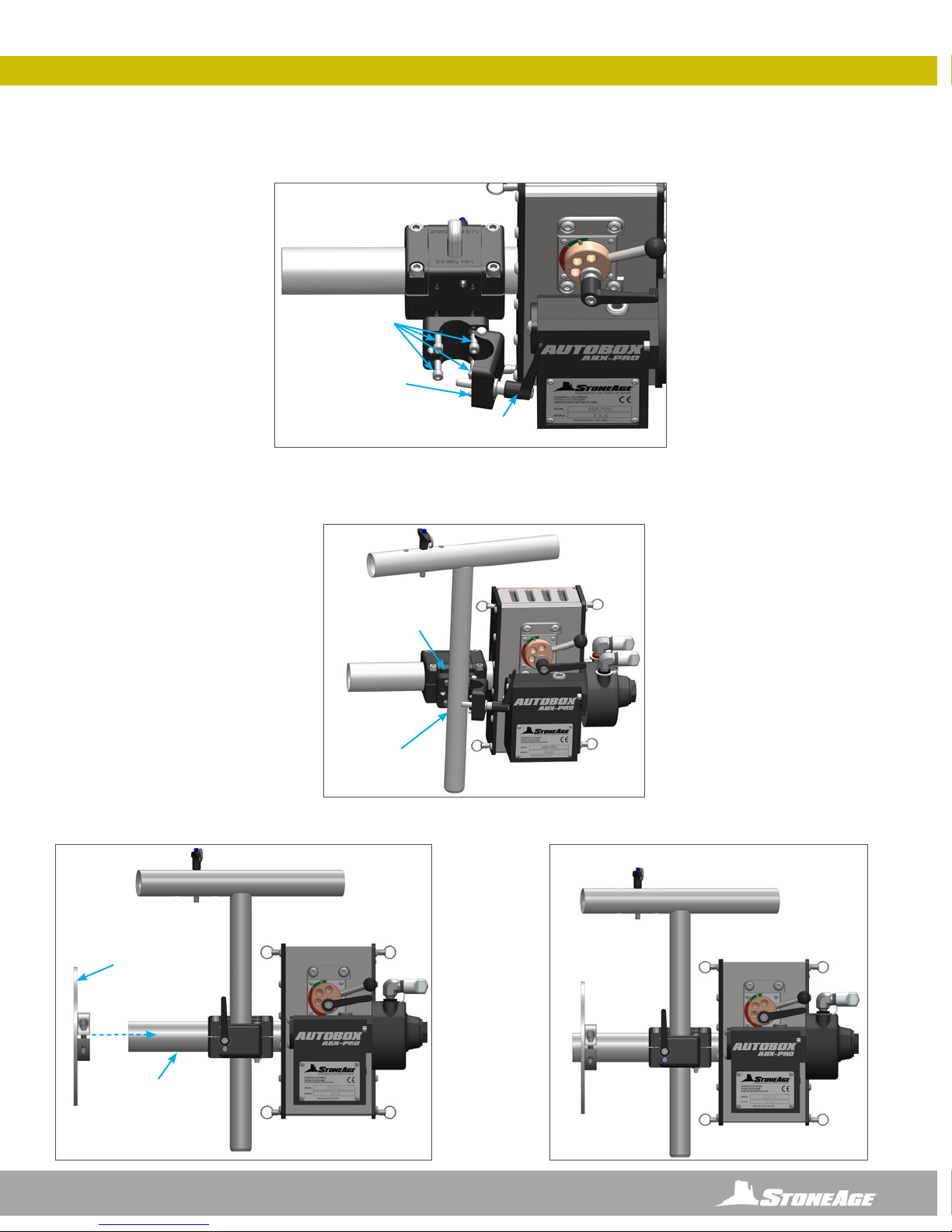
SYSTEM ASSEMBLY - OVERVIEW
THE MOUNTING OPTIONS BELOW ARE FOR USE WHEN THE PIPE JOINT WILL NOT SEPARATE ENOUGH TO ALLOW A STRAIGHT ENTRY
CONNECTION.
The BOP 082-9-45 is available through STONEAGE®for 45 BENDS. A standard 1.75” electrical conduit can also be used for connections
of varying angles.
BOP 082-9-45
1.75 X R9 X 45 DEG
SNOUT TUBE
AUTOBOX® ABX-PRO-100 ASSEMBLY
WITH OFF AXIS MOUNTING OPTIONS FOR TIGHT PIPE JOINTS
AUTOBOX® ABX-PRO-100 ASSEMBLY WITH QUARTER PLATE MOUNT
AUTOBOX® ABX-PRO-100 ASSEMBLY WITH STRAP MOUNT
NOTICE
If using electrical conduit, be sure to maintain a greater than 6” centerline radius bend to avoid constraining the movement of the tool.
10 866-795-1586 • WWW.STONEAGETOOLS.COM
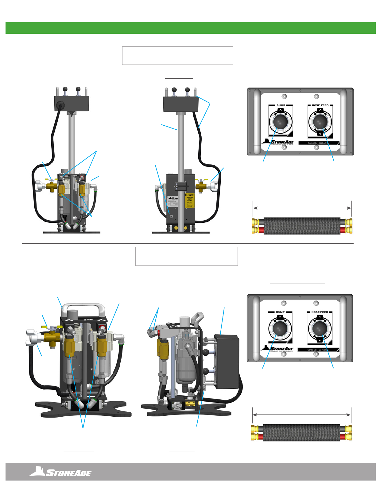
SYSTEM ASSEMBLY - OVERVIEW
PEDESTAL MOUNT OPTION
CONTROL BOX
(CB-PRO-100-P)
SIDE MOUNT OPTION
CONTROL BOX
(CB-PRO-100-S)
15’ (4572 mm)
1/2” COLOR CODED
PNEUMATIC AIR LINES
15’ (4572 mm)
1/2” COLOR CODED
PNEUMATIC AIR LINES
FRONT VIEW
FRONT VIEW
BACK VIEW
SIDE VIEW
CONTROL PANEL VIEW
CONTROL PANEL VIEW
FILTER,
REGULATOR,
LUBRICATOR
ASSEMBLY
FILTER, REGULATOR,
LUBRICATOR ASSEMBLY
ADJUSTABLE
HEIGHT
STAND
REMOTE
CONTROL
BOX WITH 8’
TETHER
REMOTE CONTROL
BOX WITH 8’ TETHER
FORWARD AND
REVERSE SPEED
CONTROLS
FORWARD AND REVERSE
SPEED CONTROLS
PUSH-TO-
CONNECT FOR
1/4” DUMP LINE
PUSH-TO-CONNECT
FOR 1/4” DUMP LINE
COLOR CODED
JIC FITTINGS
WITH DUST CAPS
COLOR CODED
JIC FITTINGS
INLET AIR
FITTING
INLET AIR
FITTING
AIR
VALVE
AIR
VALVE
CARRYING
HANDLE
HOSE FEED
LEVER
HOSE FEED
LEVER
PNEUMATIC
DUMP CONTROL
PNEUMATIC
DUMP CONTROL

11
866-795-1586 • WWW.STONEAGETOOLS.COM
QUARTER PLATE FLANGE MOUNT (BOP 010-2-4 QTR) TO PIPE AND ABX-PRO
1. Attach the Quarter Plate Flange Mount to the pipe ange using the fasteners that were removed from the ange joint. The nuts shown
between the pipe ange and the Quarter Plate Flange Mount are to allow for drainage. Other spacer options such as washers are
acceptable. (Figure 1)
2. Adjust the Quarter Plate Flange Mount by sliding it along the slots to center the inside diameter of the Hinge Clamp with the inside
diameter of the pipe. Tighten all hardware to secure in place. (Figure 2)
FIGURE 1 FIGURE 2
FIGURE 3
USE FASTENERS
REMOVED FROM THE
FLANGE JOINT
ALIGN INSIDE
DIAMETERS
Pipe shown
for graphic
representation only.
Not included in
assembly.
QUARTER PLATE FLANGE MOUNT ASSEMBLY SET-UP
BOP 030 COLLET
BLOCK ASSEMBLY
BOP 081-6
SNOUT TUBE
COLLET CAP
BLOCKS
GUIDE
TUBE
AUTOBOX® ABX-PRO
TRACTOR
3. Loosen the screws on both collet cap blocks. Slide the BOP 030 Collet Block Assembly onto the guide tube on the ABX-PRO and
tighten the two screws until secure. Slide the BOP 081-6 Snout Tube into the BOP 030 Collet Block Assembly. Push the Snout Tube in
until it stops, then tighten the two until secure. (Figure 3)

12 866-795-1586 • WWW.STONEAGETOOLS.COM
QUARTER PLATE FLANGE MOUNT ASSEMBLY SET-UP
FIGURE 4
FIGURE 5
BOP 081-6
SNOUT TUBE
ADJUSTABLE
HANDLE
4. Loosen the adjustable handle on the Hinge Clamp. Slide the Snout Tube into the Quarter Plate Flange Mount. Tighten the adjustable
handle to secure. (Figure 4)
5. The Quarter Plate Flange Mount option is now ready to be loaded with a high pressure hose. (Figure 5) Go to page 17, “Hose and
Collet Installation” for instructions.

13
866-795-1586 • WWW.STONEAGETOOLS.COM
FIGURE 1 FIGURE 2
4”-8” PLATE MOUNT ASSEMBLY SET-UP
PIPE
FLANGE
4”-8” FLANGE MOUNT PLATE (BOP 010-4-8)
1. Attach the 4”-8” Flange Mount Plate to the pipe ange using the fasteners that were removed from the ange joint. The nuts shown
between the ange and the Flange Mount Plate are to allow for drainage. Other spacer options are acceptable. (Figure 1)
2. Align the appropriate slots or pre-drilled holes to the hole pattern on the ange. Adjust the Flange Mount Plate by sliding it along the slots
to center the inside diameter of the Hinge Clamp with the inside diameter of the pipe. Tighten all hardware to secure in place. (Figure 2)
4. Loosen the adjustable handle on the Hinge Clamp. Slide the Snout Tube into the 4”-8” Plate Flange Mount. Tighten the adjustable
handle to secure. The 4”-8” Plate Flange Mount option is now ready to be loaded with the high pressure hose. (Figure 4) Go to page
17, “Hose and Collet Installation” for instructions.
FIGURE 4
BOP 081-6
SNOUT TUBE
ADJUSTABLE
HANDLE
3. Loosen the screws on both collet cap blocks. Slide the BOP 030 Collet Block Assembly onto the guide tube on the ABX-PRO and
tighten the two screws until secure. Slide the BOP 081-6 Snout Tube into the BOP 030 Collet Block Assembly. Push the Snout Tube in
until it stops, then tighten the two until secure. (Figure 3)
BOP 030 COLLET
BLOCK ASSEMBLY
BOP 081-6
SNOUT TUBE
COLLET CAP
BLOCKS
GUIDE
TUBE
AUTOBOX® ABX-PRO
TRACTOR FIGURE 3

14 866-795-1586 • WWW.STONEAGETOOLS.COM
STRAP MOUNT ASSEMBLY SET-UP
The Strap Mount Assembly (BOP 050) is designed for pipes that do not have anges.
1. Attach the strap end to the strap capture bar and wrap the strap around the pipe towards the Winch Assembly. (Figure 1)
2. Pull excess strap through the Winch Assembly and tighten down with the Ball End Handle. (Figure 2)
FIGURE 1
FIGURE 2
STRAP END TO
CAPTURE BAR
MALE
POSITIONER
BAR
WINCH
ASSEMBLY
STRAP
BALL END
HANDLE
PULL EXCESS
STRAP THROUGH
STRAP MOUNT ASSEMBLY (BOP 050) - MALE POSITIONER SIDE
Flanged pipe shown for
graphic representation only.
Not included in assembly.
STRAP MOUNT ASSEMBLY (BOP 050) - FEMALE POSITIONER SIDE
1. Loosen the screws on both collet cap blocks. Slide the BOP 030 Collet Block Assembly onto the guide tube on the ABX-PRO and
tighten the two screws until secure. Slide the BOP 081-6 Snout Tube into the BOP 030 Collet Block Assembly. Push the Snout Tube in
until it stops, then tighten the two until secure. (Figure 1)
BOP 030 COLLET
BLOCK ASSEMBLY
BOP 081-6
SNOUT TUBE
COLLET CAP
BLOCKS
GUIDE
TUBE
AUTOBOX® ABX-PRO
TRACTOR FIGURE 1
15
866-795-1586 • WWW.STONEAGETOOLS.COM
STRAP MOUNT ASSEMBLY SET-UP
FIGURE 2
FIGURE 4
FIGURE 3
BOP 058 FEMALE
POSTIONER TUBE
COMPLETE FEMALE SIDE OF STRAP MOUNT
BOP 081-6
SNOUT TUBE
SOCKET HEAD CAP
SCREWS (4)
BOP 070
HINGE CLAMP
ASSEMBLY
BOP 012
SPLASH PLATE
ASSEMBLY
ADJUSTABLE
HANDLE
BOP 070
HINGE CLAMP
ASSEMBLY
2. Release the Adjustable Handle on the BOP 070 Hinge Clamp to access the 4 socket head cap screws. Locate the side of the BOP
030 Collet Block Assembly with 4 threaded holes. Orient the Hinge Clamp so that the hinge is on the right. Fasten the Hinge Clamp
Assembly to the Collet Block Assembly using the 4 supplied socket head cap screws. (Figure 2)
3. Insert the BOP 058 Female Positioner Assembly into the Hinge Clamp Assembly then close the Hinge Clamp Assembly and tighten the
Adjustable Handle. The Female Positioner height can be adjusted in the open or closed position and is designed to be adjustable
based on the size of the pipe. (Figure 3)
4. To Install the BOP 012 OPTIONAL Splash Plate, loosen the two bolts on the collar, slide it onto the BOP 081-6 Snout Tube and hand
tighten the collar bolts when in position. (Figure 4)

16 866-795-1586 • WWW.STONEAGETOOLS.COM
HOSE AND COLLET INSTALLATION
FEMALE POSITIONER ARM TO MALE POSITIONER ARM CONNECTION
FIGURE 1
FIGURE 1.1
FEMALE
POSITIONER
ARM
MALE
POSITIONER
ARM
QUICK
RELEASE PIN
QUICK
RELEASE PIN
STRAP MOUNT ASSEMBLY SET-UP
WARNING
Prior to use, always tighten and test the Backout Preventer to ensure the tool does not pass backward toward the Collet Block Assembly.
Failure to do so can result in severe injury and/or death.
1. Slide the Female Positioner Arm onto the Male Positioner Arm. (Figure 1) Line up the incremental holes and push the Quick Release
Pin through both positioner arms. (Figure 1.1)

17
866-795-1586 • WWW.STONEAGETOOLS.COM
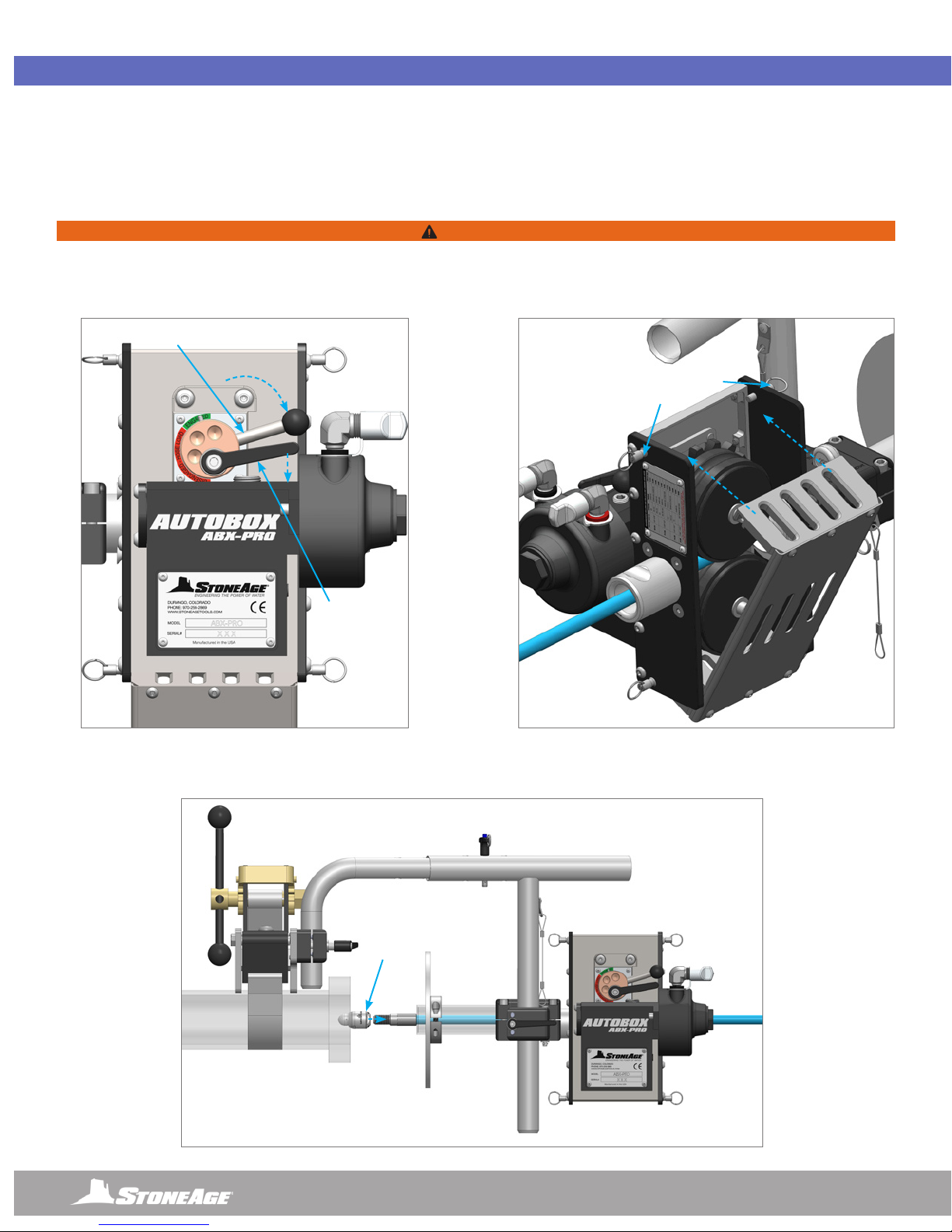
1. To load a hose, release the Adjustable Handle and rotate the Cam Lever until the Indicator Pin is in the “Disengaged” position. This
opens up the space between the rollers. (Figure 1)
2. Pull out the Quick Release Pin and remove the Collet. Feed the male hose end into the guide tube, through the rollers and out the end
of the BOP 081-6 Snout Tube. (Figure 2) Go to page 23, “Roller and Collet Selection” to determine the appropriate size Rollers
and Collets for the high pressure hose diameter.
CAM LEVER
ADJUSTABLE
HANDLE
INDICATOR
PIN
“DISENGAGED”
FIGURE 1
HOSE AND COLLET INSTALLATION
LOADING THE HIGH-PRESSURE HOSE
NOTICE
Only high quality hoses intended for waterblast applications should be used as high-pressure hoses. Pressure rating of high-pressure hoses
MUST NEVER be exceeded. Do not use a shrouded hose or hose with a steel protective cover. This will cause severe damage to the Rollers.
FIGURE 2
COLLET
QUICK
RELEASE
PIN
MALE
HOSE
END
ROLLERS
GUIDE
TUBE
18 866-795-1586 • WWW.STONEAGETOOLS.COM
HOSE AND COLLET INSTALLATION
3. Rotate the Cam Lever clockwise to the “Engaged” position to tighten the Idler Roller down onto the hose. There should be a
slow slip on the hose. If the slip is too tight or loose, move the Eccentric Lever off until a slow slip is obtained. Once the slip level is
achieved, push down on the Adjustable Handle to tighten the bushing assembly. (Figure 3)
4. Push the back cover back into the closed position and secure the two Quick Release Pins on the top of the AUTOBOX® ABX-PRO
TRACTOR. (Figure 4)
5. Attach the desired tool onto the male hose end (Stoneage®BT25 Beetle® shown for reference). SEE THE APPLICABLE TOOL MANUAL
FOR SPECIFIC INSTALLATION INSTRUCTIONS.
FIGURE 3 FIGURE 4
FIGURE 5
QUICK RELEASE
PINS
TOOL
CAM
LEVER
ADJUSTABLE
HANDLE
“ENGAGED”
WARNING
Prior to use, always tighten and test the backout preventer to ensure the tool does not pass backward toward the Collet Block Assembly.
Failure to do so can result in severe injury and/or death. It is the responsibility of the user to select proper collet sizing to assure the end of
the hose will not pass through the collet.

19
866-795-1586 • WWW.STONEAGETOOLS.COM
PNEUMATIC AIR LINE CONNECTIONS
4. Pull the Dust Caps off the Pneumatic Air Fittings. Connect the Pneumatic Supply Lines from the CB-ABX-PRO-100-X Control Box to
the AUTOBOX® ABX-PRO-100. Pay close attention to the color coded tabs on the air ttings of the Air Motor and the Control Box.
Connect the red hose to the red banded air ttings and the black hose to the black banded air ttings. (Figure 4 & 5)
FIGURE 4
AIR MOTOR ON TRACTOR ASSEMBLY
CONTROL BOX WITH PEDESTAL MOUNT
AIR FITTINGS ON CONTROL BOX ASSEMBLY
FIGURE 5
PNEUMATIC SUPPLY
LINES
15 FT / 4572 mm
AIR FITTING
LOCATIONS
CONTROL BOX SET-UP
20 866-795-1586 • WWW.STONEAGETOOLS.COM
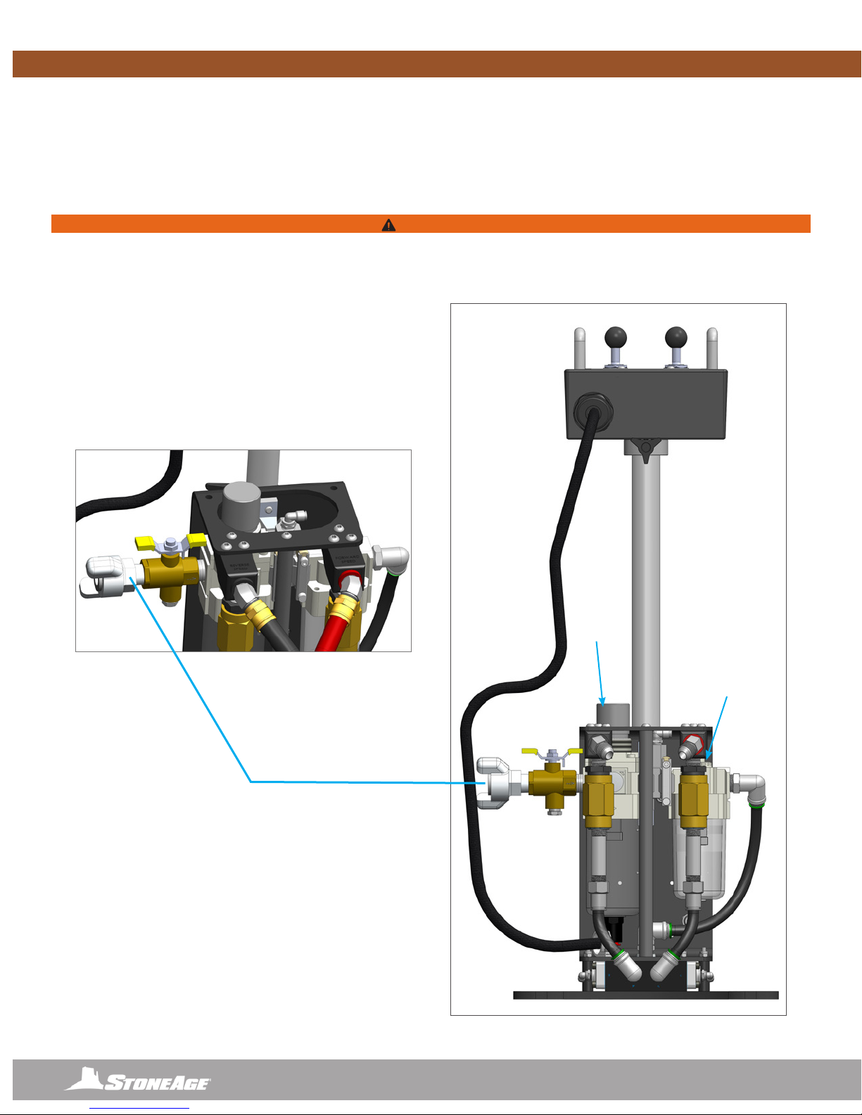
CONTROL BOX SET-UP
AIR SUPPLY AND LUBRICATOR SETTING
1. The Control Box is supplied with a twist claw style inlet coupling (Chicago style) located on the side of the FRL Assembly. Connect
a compatible compressed air line (not included) according to the Manufacturer’s instructions. If another pneumatic connection is
preferred, this tting can be removed and any male 1/2 in NPT tting may be used.
2. Using the pressure regulator on the FRL, adjust the operating pressure to 100 psi (0.7 MPa) for the application.
ADJUST INLINE
OILER TO FEED
1 DROP OF OIL
EVERY 30-60
SECONDS FOR
HIGH SPEED OR
CONTINUOUS
DUTY USAGE
PRESSURE
REGULATOR
AIR SUPPLY FITTING
A universal AIR SUPPLY FITTING (Chicago style) is
located on the FRL. Connect a compatible compressed
air line (not included) according to the manufacturer’s
instructions. If another pneumatic connection is preferred,
this tting can be removed and any male ½ in NPT tting
may be used.
WARNING
Maximum operating pressure is 100 psi (0.7 MPa). Never exceed 125 psi (0.86 MPa) supply pressure. Exceeding 125 psi (0.86 MPa)
supply pressure may result in injury to the Operator and/or damage to the equipment.
Table of contents
Other StoneAge Pipe Cleaner manuals


Popular Pipe Cleaner manuals by other brands

Wöhler
Wöhler DH 420 operating manual

Westfalia
Westfalia 82 45 38 instruction manual

Stihl
Stihl 4910-500-8000 instruction manual

Westfalia
Westfalia 83 01 56 instruction manual

Conmetall Meister
Conmetall Meister SA220 quick guide

General Pipe Cleaners
General Pipe Cleaners Speedrooter 92R operating instructions