On the same terminal block plug, connect the Wiegand Data 1 from the same Wiegand
input channel at the Access Control Panel to Pin 3 on the terminal block plug. (NOTE: Pin
3 will be the terminal on the bottom when the terminal block is plugged into the GO.)
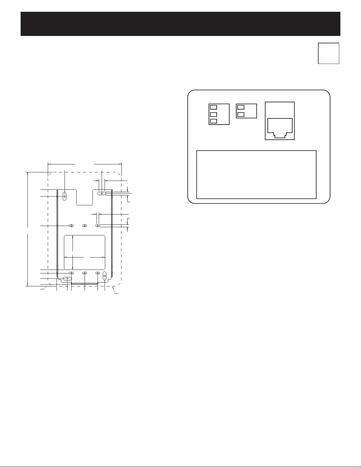
2.2.4 Final Installation
Insert the terminal block plugs into TB1 and TB2 on the GO as indicated by the label on
the back of the unit.
Insert the RJ45 plug into the RJ45 receptacle on the back of the GO to apply power
and provide a network connection. After the unit boots, the Anti-Tamper Alarm should
begin to sound.
Place the GO against the mounting bracket such that the 4 tabs along the sides of the
bracket align with the 4 slots on the back plate of the GO. Then, press the GO against
the wall and slide it down so that the bottom of the GO touches the metal tongue of the
mounting bracket. Insert and tighten the two T10 Torx Security Screws supplied with
the GO through the bottom of the metal tongue of the mounting bracket. Once the unit
is secure, the Anti-Tamper Alarm should no longer sound.
3 The Display
3.1 Gateway Connection Indication
When the GO is connected to the Gateway, the STONELOCK icon on the display will go
from all GRAY to WHITE and GRAY.
3.2 QR Code Icon
When a valid QR Code is read by the StoneLock GO, the QR Code icon on the display
will change from GRAY to GREEN.
When an invalid QR Code is read by the StoneLock GO, the QR Code icon on the
display will change from GRAY to RED.
Reference the StoneLock Gateway User’s Manual for information about QR Codes.
3.3 Verifying at the GO
When a user is verifying at a StoneLock GO, they should always stand approximately
arm’s length and use the same relaxed, non-expressive face that was used during
enrollment. During verification, a user will know that their face is being scan because a
Green bar will move up and down in front of the face icon on the display.
If the verification is successful, the face icon and the “LOCK” portion of the STONELOCK
icon on the display will momentarily appear Green.
If the verification fails and the user is denied, the face icon and the “LOCK” portion of
the STONELOCK icon on the display will momentarily appear RED.
3.4 Lock Status Indication
When the Access Control Panel signals for the lock to release, the icon in the upper
right corner of the StoneLock GO display will change from a GRAY locked Lock icon
to a GREEN unlocked Lock icon. When the Access Control Panel stops the signal, the
icon will change to a RED locked Lock icon. It will stay Red until the next input from the
Access Control Panel.
4 Configure GO IP Address
Reference the StoneLock Gateway Installation and User’s Manual for information about
configuring the GO IP Address.
5 Enrolling a User
Reference the StoneLock Gateway Installation and User’s Manual for information about
enrolling a user.
6 Specifications
6.1 Connections
RJ45 Connector PoE (Power Over Ethernet)
• Input Voltage: 37 – 57 VDC
• Input Current: 350mA
• Input Power: 12.95W
• Power Supply: Power Limited/Class 2, PoE IEEE802.3af
• Output Data Voltage: +/- 2.5V (over twisted pair)
• Output Data Current: 65mA Max
• Output Data Power: N/A (the device is a PoE Power Device (PD)
TB1 Wurth Electronics P/N: 691361100002 (Supplied with unit)
• Input Voltage: 12VDC
• Input Current: 4mA
• Wire Gauge: 26AWG – 16AWG
TB2 Wurth Electronics P/N: 691361100003 (Supplied with unit)
• Output Voltage: 0-5VDC
• Output Current: 5mA
• Wire Gauge: 26AWG – 16AWG
6.2 False Acceptance Rate (FAR)
<0.0004%
6.3 Ambient Operating Temperature
32°F (0°C) - 120°F (49°C)
6.4 Ambient Operating Humidity
0-85%RH, non-condensing
Environmental Grade 1, Indoor dry conditions
7 Agency Approvals
UL 294 Grade 1
CAN/ULC 60839-11-1
Environmental Class 1
Note: This equipment has been tested and found to comply with the limits for a Class
B digital device, pursuant to part 15 of the FCC Rules. These limits are designed to
provide reasonable protection against harmful interference in a residential installation.
This equipment generates, uses and can radiate radio frequency energy and, if not
installed and used in accordance with the instructions, may cause harmful interference
to radio communications. However, there is no guarantee that interference will not
occur in a particular installation. If this equipment does cause harmful interference to
radio or television reception, which can be determined by turning the equipment o
and on, the user is encouraged to try to correct the interference by one or more of the
following measures:
—Reorient or relocate the receiving antenna.
—Increase the separation between the equipment and receiver.
—Connect the equipment into an outlet on a circuit dierent from that to which the
receiver is connected.
—Consult the dealer or an experienced radio/TV technician for help.
This device complies with part 15 of the FCC Rules and ICES-003 for Canada.
Operation is subject to the following two conditions: (1) This device may not cause
harmful interference, and (2) this device must accept any interference received,
including interference that may cause undesired operation of the device.
A StoneLock Publication © 2022All rights reservedRev 220915
Technical Support
800.970.6168 Option 2
support@stonelock.com
www.stonelock.com