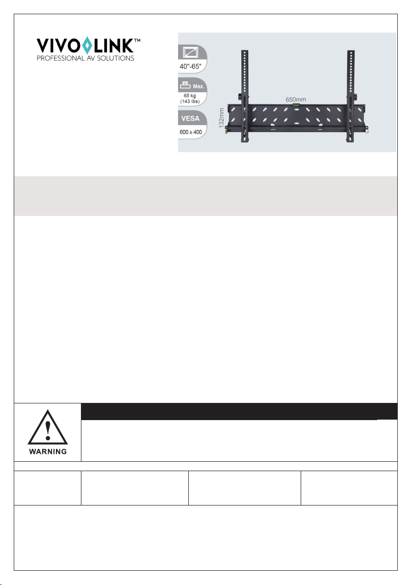
Vivo Link VLMW4065T User manual

ADVARSEL!
Dette beslag skal være forsvarligt fastgjort til væggen. Hvis beslaget ikke
er monteret korrekt, kan det resultere i at skærmen falder ned og eventuelt
beskadiger personer eller udstyr.
Bemærk: De skruer og beslag, der følger med denne indpakning, er ikke beregnet til montering i stål
konstruktioner og vægge af cementblokke, og du bedes derfor kontakte den lokale AV-installatør for
vejledning om hvilket tilbehør, som egner sig bedst til dette formål.
• 4 mm træbor
• 8 mm betonbor • Topnøglesæt
• Lægte søger • Stjerneskruetrækker
• Tommestok
INSTALLATIONS-
VEJLEDNING
VLMW4065T
Udpakningsinstruktioner
Åben indpakningen forsigtigt og læg indholdet på et stykke pap eller en anden beskyttende over-
ade for at undgå beskadigelse. Kontroller at pakkens indhold stemmer overens med tilbehørs-
oversigten på næste side. Kontroller også om de medfølgende komponenter er modtaget ube-
skadiget. Brug ikke beskadigede eller defekte dele.
Vigtige sikkerhedsoplysninger
Montér og brug dette beslag med varsomhed. Læs venligst vejledningen inden påbegyndelse
af montering og følg nøje alle instruktioner. Benyt passende sikkerhedsudstyr under montering.
Kontakt venligst en kvaliceret håndværker for hjælp hvis du ikke forstår vejledningen eller er i
tvivl om sikkerheden ved montering. Hvis du er i tvivl om konstruktionen af din væg, bedes du
konsultere en kvaliceret installatør.
Brug ikke dette produkt til andre formål, eller i andre kongurationer end de udtrykkeligt angivne
i denne vejledning. Vi fraskriver os hermed ethvert ansvar eller skade som følge af forkert monte-
ring eller forkert brug af dette produkt.
1
Nødvendigt
værktøj
Vægt:
SVESA tandarder Op til 65 kg (1453 lbs)
Op til 600x400
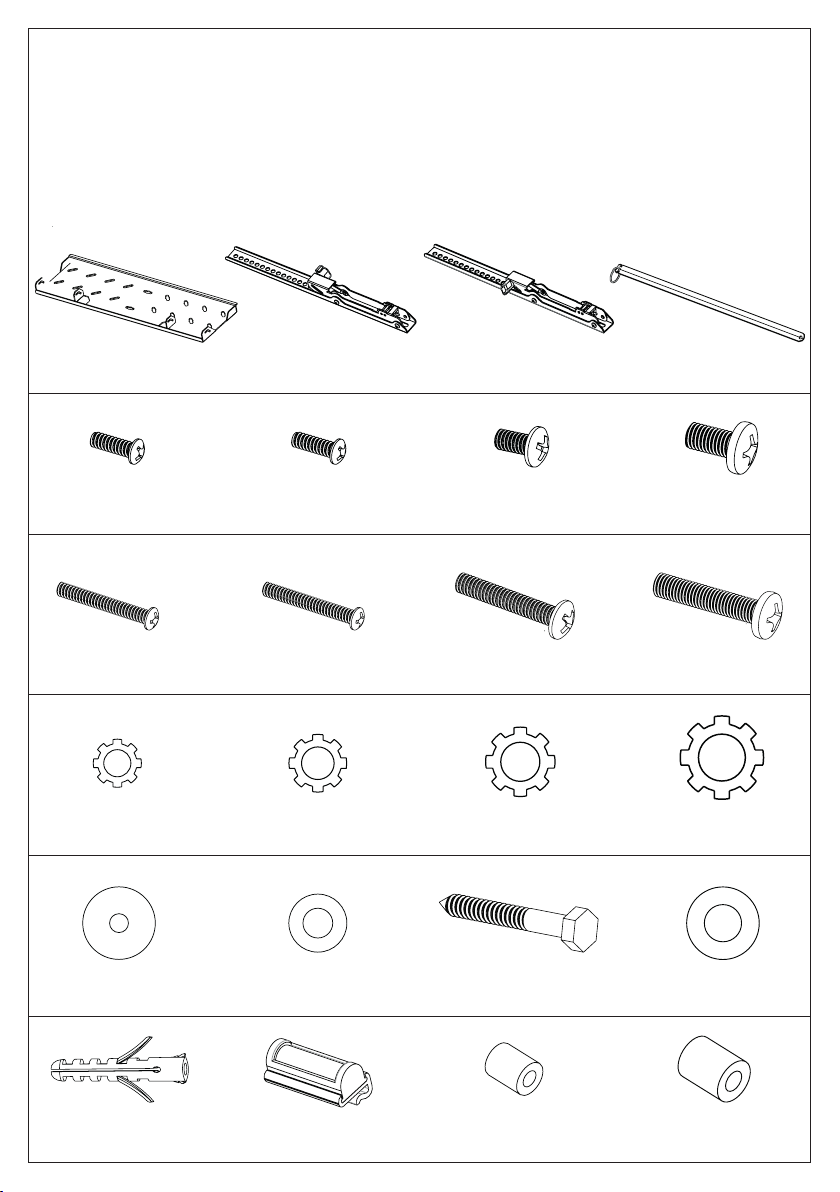
TILBEHØRSOVERSIGT
(1) Vægplade – a (1) Skærmbeslag – b1 (1) Skærmbeslag - b2 (1) Låsestang – c
2
(4) M4x12 Bolt - d (4) M5x12 Bolt - e (4) M6x12 Bolt - f (4) M8x20 Bolt - g
(4) M4 Låseskive - h (4) M5 Låseskive - i (4) M6 Låseskive - j (4) M8 Låseskive - k
(8) M4/M5 Spændeskive - l (4) M6/M8 Spændeskive - m (5) Fransk skrue - n (5) Spændeskive - o
(4) M4x30 Bolt - dd (4) M5x30 Bolt - ee (4) M6x35 Bolt - (4) M8x40 Bolt - gg
(5) Rawlplugs - p (1) Vatterpas - q (4) M4/M5 Afstandsskive - r (4) M6/M8 Afstandsskive - s

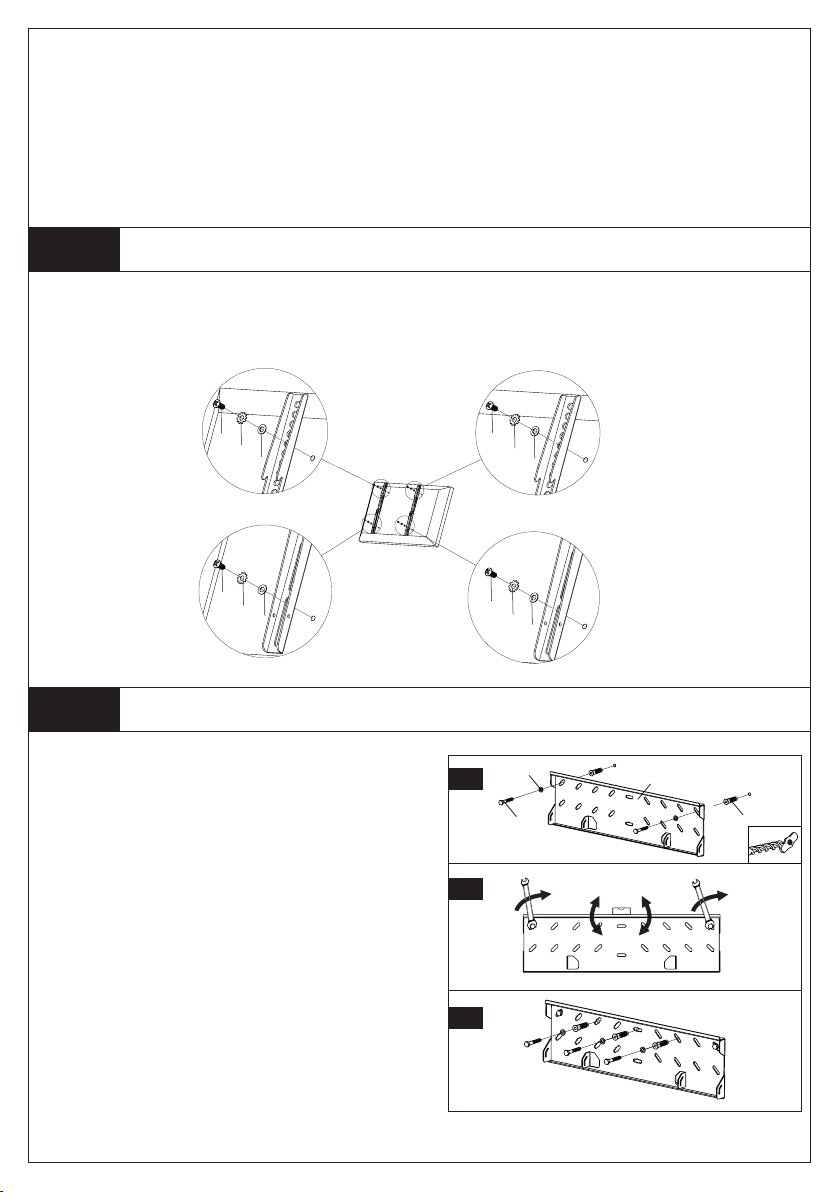
Montering af skærmbeslag på en skærm med ad bagside
Montering af vægpladen
Step 1
Step 2A
Fastslå først og fremmest hvilken størrelse bolte (d, e, f, g, dd, ee, , gg) din skærm kræver, følg derefter ned-
enstående tegning. Boltene skrues fast til skærmen ved hjælp af de dertilhørende låseskiver (h, i, j, k) samt
spændeskiver (l, m). Vær sikker på at skærmbeslagene (b) er vertikalt centreret og at de er på niveau med
hinanden. Brug kun afstandsstykkerne (r, s) hvis boltene er for lange.
3
M4 Diameter Bolt M6 Diameter Bolt
M5 Diameter Bolt M8 Diameter Bolt
d
hl
e
il
f
jm
g
km
Montering på mursten, fast beton og betonblok:
Brug vægpladen (a) som skabelon til at markere to
huller på væggen. Et i øverste venstre hjørne og et i
øverste højre hjørne. Vær sikker på at hullerne er i vatter.
Forbor hullerne med et 8 mm betonbor til mindst 50
mm i dybden. Indsæt rawlplugs (p) i hvert hul. Sørg for,
at alle rawlplugs sidder helt plant med betonoveraden.
Fastgør vægpladen til væggen ved hjælp af to franske
skruer (n), to spændeskiver (o) og to rawlplugs (p) som
vist i Diagram 2a. Juster niveau som vist i Diagram 2b og
skru de franske skruer (n) fast. Bor endnu tre huller som
vist i Diagram 2c og skru de 3 sidste franske skruer (n),
spændeskiver (o) og rawlplugs (p) fast.
2a
1
22
2b
2c
n
o
p
a

TAK FORDI DU HAR VALGT ET AF VORES PRODUKTER.
Montering af vægpladen
Fastgør låsestang og montér skærm på vægpladen
Step 2B
Step 3
Advarsel:Til nogle skærme kræves to personer til at løfte!
Indsæt låsestangen (c) i vægbeslaget som vist i diagram 3a. Når låsestangen er ført hele vejen igennem væg-
beslaget, kan en hængelås benyttes for yderligere sikkerhed. Hægt herefter skærmbeslaget (b) fast til toppen
af vægpladen (a) og før bunden af skærmbeslaget ind til bunden af væg-pladen, som vist i diagram 3b. Til sidst
låses vægbeslaget til vægpladen ved at trykke bunden af skærmen
mod vægpladen, som vist i Diagram 3c. For at justere hældningsvinklen
på skærmen, skal du løsne grebene på de to skærmbeslag (b1 og b2).
Ønsker du på et tidspunkt at afmontere skærmen fra væg-pladen, skal
låsestangen ernes først.
Montering på trælægte
Vægpladen (a) skal monteres på to trælægter med mindst 16”(406
mm) mellemrum. Brug en lægtesøger til at nde lægterne. Det
kan være en god idé at bruge en syl eller et søm til at bestemme,
hvor lægterne er placeret. Forbor, med et 4 mm træbor, et 50 mm
dybt hul i den ønskede højde på hver lægte. Sørg for, at hullerne er
placeret midt på lægten og at de er på niveau med hinanden. Brug
vægpladen som skabelon når du skal markere hullerne. Fastgør
vægpladen til væggen ved hjælp af re franske skruer (n) og re
spændeskiver (o).
4
n
o
a
c
a
3a
3b
b1 ,b 2
a
3c
INSTALLATION
INSTRUCTION
VLMW4065T
CAUTION!
This monitormount mustbe securelyattached tothe vertical wall. If themount
is not properly installed it may fall, resulting in possible injury and/or damage.
Note: The mounting components and hardware supplied in this package are not designed for installa-
tions to walls with steel studs or to cinder block walls. If the hardware you need for your installation is
not included, please consult your local hardware store for proper mounting hardware for the application.
Unpacking Instructions
Carefully open the carton, remove contents and lay out on cardboard or other protective surface
to avoid damage. Check package contents against the Supplied Parts List in the next page to
assure that all components were received undamaged. Do not use damaged or defective parts.
Important Safety Information
Install and operate this device with care. Please read this instruction before beginning the instal-
lation, and carefully follow all instructions contained herein. Use proper safety equipment during
installation. Please call a qualied installation contractor for help if you don’t understand these
directions or have any doubts about the safety of the installation. If you are uncertain about the
nature of your wall, consult a qualied installation contractor.
Do not use this product for any purpose or in any conguration not explicitly specied in this
instruction. We hereby disclaims any and all liability or damage arising from incorrect assembly,
incorrect mounting or incorrect use of this product.
5
• 4 mm Drill bit
• 8 mm Masonry Bit • Philips Screwdriver
• Stud Finder • Wrench or Socket Set
• Carpenter’s Level
Tools Required
SVESA tandard: Weight:
Up to 65 kg (1453 lbs)
Up to 600x400
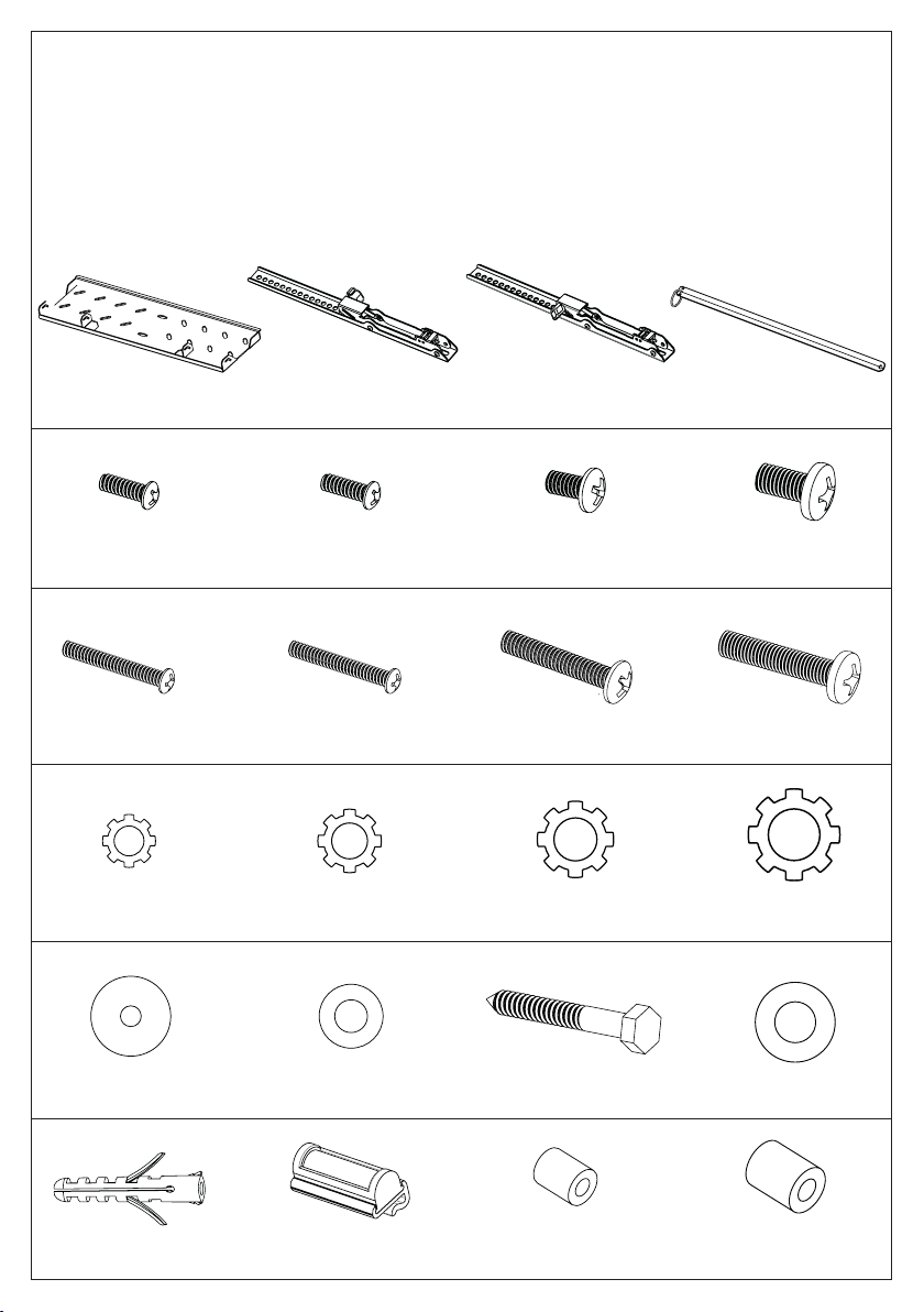
SUPPLIED PARTS LIST
ENGLISH
(1) Wall Plate – a (1) Monitor Bracket - b1 (1) Monitor Bracket - b2 (1) Locking Bar – c
6
(4) M4x12 Bolt - d (4) M5x12 Bolt - e (4) M6x12 Bolt - f (4) M8x20 Bolt - g
(4) M4 Lock Washer - h (4) M5 Lock Washer - i (4) M6 LockWasher - j (4) M8 Lock Washer - k
(8) M4/M5 Washer - l (4) M6/M8 Washer - m (5) M6x45Lag Bolt - n (5) Lag Bolt Washer - o
(5) Concrete Anchor - p (1) Bubble Level - q (4) M4/M5 Spacer - r (4) M6/M8 Spacer - s
(4) M4x30 Bolt - dd (4) M5x30 Bolt - ee (4) M6x35 Bolt - (4) M8x40 Bolt - gg
ENGLISH
Mounting the Monitor Brackets to a Monitor with Flat Back
Mounting the Wall Plate to the Wall
Step 1
Step 2A
First of all, make sure which diameter of the Bolt (d, e, f, g, dd, ee, , gg) your monitor requires. Once you have deter-
mined the correct diameter, please see the relative diagram as below. You will thread the Bolt into the monitor us-
ing the correct Lock Washer (h, i , j, k) and Washer (l, m). Please make sure that the Monitor Brackets (b) are vertically
centered and level with each other. Use the Spacers (r, s) only if the bolts are too long.
7
M4 Diameter Bolt M6 Diameter Bolt
M5 Diameter Bolt M8 Diameter Bolt
d
hl
e
il
f
jm
g
km
Brick, Solid Concrete and Concrete Block mounting:
Use the Wall Plate (a) as a template to mark 3 hole loca-
tions on the wall. One in the top left slot and another
one in the top right slot. Pre-drill these holes with a 8
mm masonry bit to at least 50 mm in depth. Insert a
Concrete Anchor (p) into each of these holes. Make sure
the anchor is seated completely ush with the concrete
surface even if there is a layer of drywall or other mate-
rial in front. Attach the Wall Plate to the wall using 2 Lag
Bolts (n), 2 Lag Bolt Washers (o) and 2 Concrete Anchor
(p), as shown in Diagram 2A. Adjust the level as shown
in Diagram 2b, fasten the Lag Bolts (n). Drill three
more holes as shown in Diagram 2c and attach the rest
3 Lag Bolts (n), Lag Bolt Washers (o) and Concrete
Anchor (p).
2a
1
22
2b
2c
n
o
p
a
ENGLISH
THANKS FOR CHOOSING ONE OF OUR PRODUCTS.
Mounting the Wall Plate to the Wall
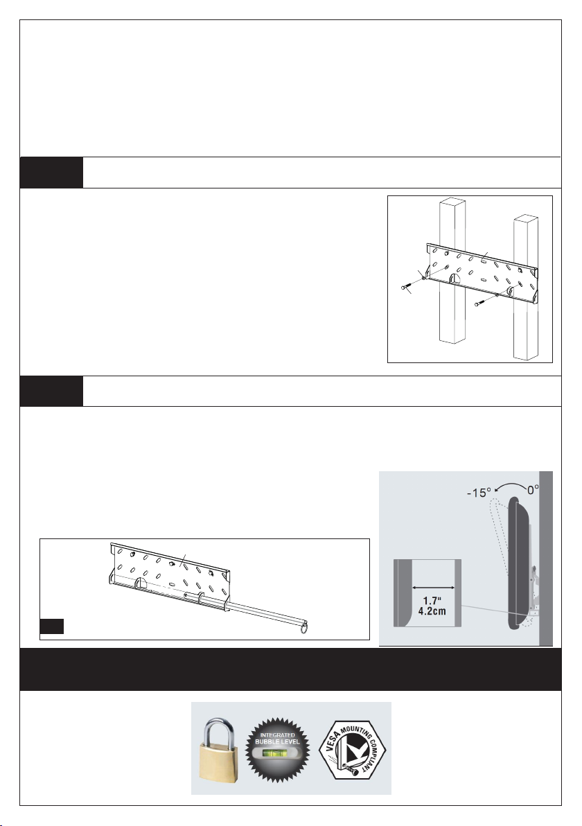
Insert the Locking Bar and attach the Monitor to Wall Plate
Step 2B
Step 3
Warning: Some monitors may require two people to lift!
Insert the Locking Bar (c) to the Wall Plate (a) as shown in the Diagram 3a. If necessary add a padlock (not
supplied) at the end of the locking bar. Hook the Monitor Brackets (b) over the top of the Wall Plate (a) and
then let the bottom of the Monitor Brackets rotate to the bottom of the Wall Plate as shown in the Diagram
3b. Push the bottom of the monitor to lock the Monitor Brackets on
the Wall Plate, as shown in the Diagram 3c. Loose the knobs on both
Monitor Brackets to adjust the tilt angle according to your requirement.
Pull out the Locking Bar rst if you want to remove the monitor from
the Wall Plate.
Wood Stud mounting:
The Wall Plate (a) must be mounted to two studs at least 16”(406 mm)
apart. Use a stud nder to locate two adjacent studs. It is a good idea
to verify where the studs are located with an awl or thin nail. Pre-drill a
50 mm deep hole at the desired height in each stud using a 4 mm drill
bit. Make sure these holes are in the center area of the studs and level
with each other. Use the Wall Plate as a template to mark the location
of the second hole in each stud. Drill 50 mm deep holes using the 3.8
mm drill bit in the marked locations. Attach the Wall Plate to the wall
using the 4 Lag Bolts (n) and 4 Lag Bolt Washers (o).
8
n
o
a
c
a
3a
3b
b1 ,b 2
a
3c
Table of contents
Languages:
Other Vivo Link TV Mount manuals


