StorageWorks 2611S120 Instruction Manual
OPERATING AND
SAFETY MANUAL
MODEL
2611S120
60" STORAGE SHELF OR WORKBENCH
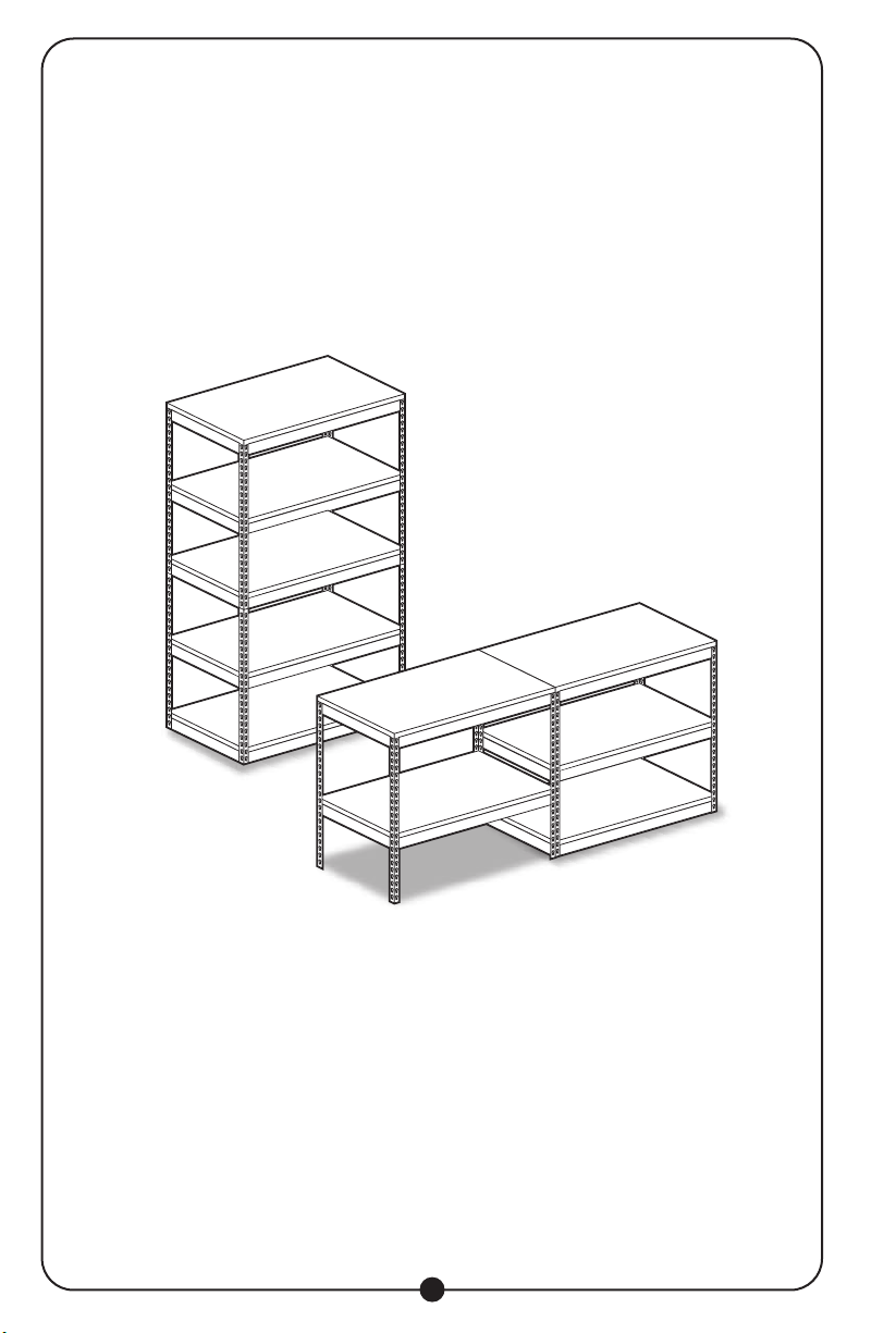
TABLE OF CONTENTS
MPORTANT SAFETY INSTRUCTIONS....................................................................3
TOOLS REQUIRED.............................................................................................. 3
PARTS LIST ....................................................................................................... 4
GENERAL INSTRUCTIONS ................................................................................... 5
WORKBENCH ASSEMBLY .................................................................................... 5
STORAGE SHELF ASSEMBLY ...............................................................................9
WARRANTY ..................................................................................................... 14
2
2

IMPORTANT SAFETY INSTRUCTIONS
FAILURE TO READ AND FOLLOW ALL INSTRUCTIONS IN THIS MANUAL MAY RESULT
IN INJURIES OR DEATH. SAVE THESE INSTRUCTIONS FOR FUTURE USE.
ATTENTION
PRODUCT IS NOT RECOMMENDED FOR OUTDOOR USE. THE PARTICLE BOARD SHELVES
SHOULD BE SEALED WITH A WATERPROOF SEALANT OR PAINT WHEN USED IN HUMID
ENVIRONMENTS TO PROTECT FROM MOLD.
TOOLS REQUIRED
1. Hammer
2. Rubber Mallet
Read all Instructions before assembly.
This product is suitable for indoor use only. Warranty is void if
used in wet or excessively humid conditions.
This unit should be securely anchored to the wall with suitable
fasteners, which are NOT included.
Units should be placed on a level surface. Failure to do so can
result in poor product performance or create a possible safety
hazard. Avoid assembly on carpet.
Do not use this product for anything other than the
manufacturer's intended purpose. Do not stand on the unit or
use it as a ladder!
Evenly distribute the weight on each shelf and keep the
heaviest loads on the bottom shelf.
Use care when working with metal parts. The use of safety
gloves is strongly recommended.
It is recommended that at least two people assemble
the unit together.
3
180º
1 2

4
PARTS LIST
UNPACK ALL PARTS AND MAKE SURE ALL PIECES ARE PRESENT BEFORE
CONTINUING WITH ASSEMBLY.
Item Description Qty.
1Corner Post 8
2Long Double Rivet Beam 10
3Short Double Rivet Beam 10
4Shelves 5
5 Post Joint 4
6 Post Cap 16
NOTE:
The package contents shown above will build either the storage shelf configuration or the
workbench configuration, as shown in the illustration on the second page of this manual.

5
GENERAL INSTRUCTIONS
Assembly is done with the rivets of the beams fitting into the slots of the posts. A rubber
mallet should be used on the beams to secure the rivets properly. A hammer can also
be used, providing one uses a cloth or block of wood between the hammer head and
the parts, to prevent damage. Tap gently and be sure the rivets are straight and fully
engaged.
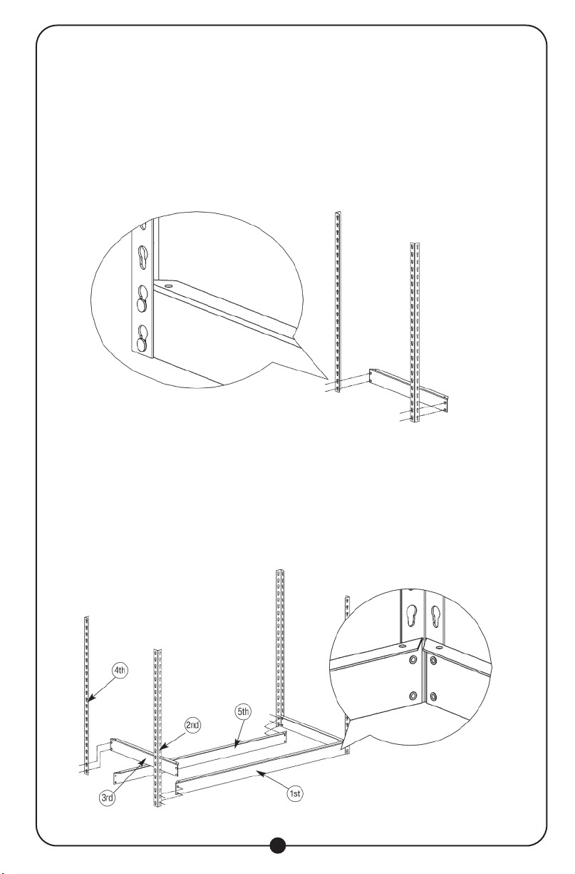
WORKBENCH ASSEMBLY
STEP 1
Start bottom of frame assembly by joining a short double rivet beam (item 3) into the
two bottom keyholes of a corner post (item 1). Be sure that the flange is facing up, then
drive the rivets into the bottom of the key hole by hitting the beam with a rubber mallet.
Repeat this action with the second corner post (item 1), now creating one bottom end
section.
Tip: Hit the beam close to joints, locking the pieces together.

6
STEP 2
Assemble a long double rivet beam (item 2) to the bottom key holes of the bottom end
section (refer to detail). Hit the beam near the joints with a rubber mallet, to lock pieces
together. Add the corner post and a short double rivet beam (item 3). All beam flanges
must be facing up. Follow the order 1 through 5 shown in the drawing to complete the
assembly.
Note: Hit the beams near the joints with a rubber mallet to lock the pieces into place.
STEP 3
Add the short and long double rivet beams to the top two key holes of each corner post
(refer to detail). Be sure all flanges are facing up. Hit the beam near the joints with a
rubber mallet, to lock pieces together.

7
STEP 4
Add two short double rivet beams (item 3) and two long double rivet beams (item 2) with
flanges facing up, to your desired height, and hit the beams near the joints with a rubber
mallet, to lock pieces together. This section of the bench is now complete.
STEP 5
For the next section, start by assembling two corner posts and two short double rivet
beams. The first short double rivet beam must be assembled to the top two keyholes of
the corner post. The second short double rivet beam must be assembled at the 7th-8th
keyhole from the bottom of the corner post. Repeat for the opposite end. Hit the beam
near the joints with a rubber mallet, to lock pieces together.

8
STEP 6
Assemble two long double rivet beams (item 2) to the top two keyholes of the corner
post, on each side. Assemble the two long double rivet beams at the 7th-8th keyhole. Hit
the beam near the joints with a rubber mallet, to lock pieces together.
STEP 7
Add post caps to the top and bottom of each angle post. Place the shelves into position.
Slide shelves in at an angle, then position so they are resting on the flanges.
9
STORAGE SHELF ASSEMBLY
STEP 1
Begin the bottom of frame assembly by joining a short double rivet beam (item 3) into
the two bottom keyholes of a corner post (item 1). Be sure that the flange is facing up,
then drive the rivets to the bottom of the key hole by hitting the beam with a rubber mal-
let. Repeat to add the second corner post, creating a bottom end section.
Tip: Hit the beam with a rubber mallet, close to the joints, locking the pieces together.
STEP 2
Assemble a long double rivet beam (item 2) to the bottom key holes of the bottom end
assembly (refer to detail). Hit the beam near the joints with a rubber mallet, to lock
pieces together. Add the corner post and a short double rivet beam. Be sure that all
beam flanges are facing up. Follow instructions 1 through 5 as shown in the drawing, to
complete the assembly.
Note: Hit the beams near the joints, with a rubber mallet, to lock the pieces into place.

10
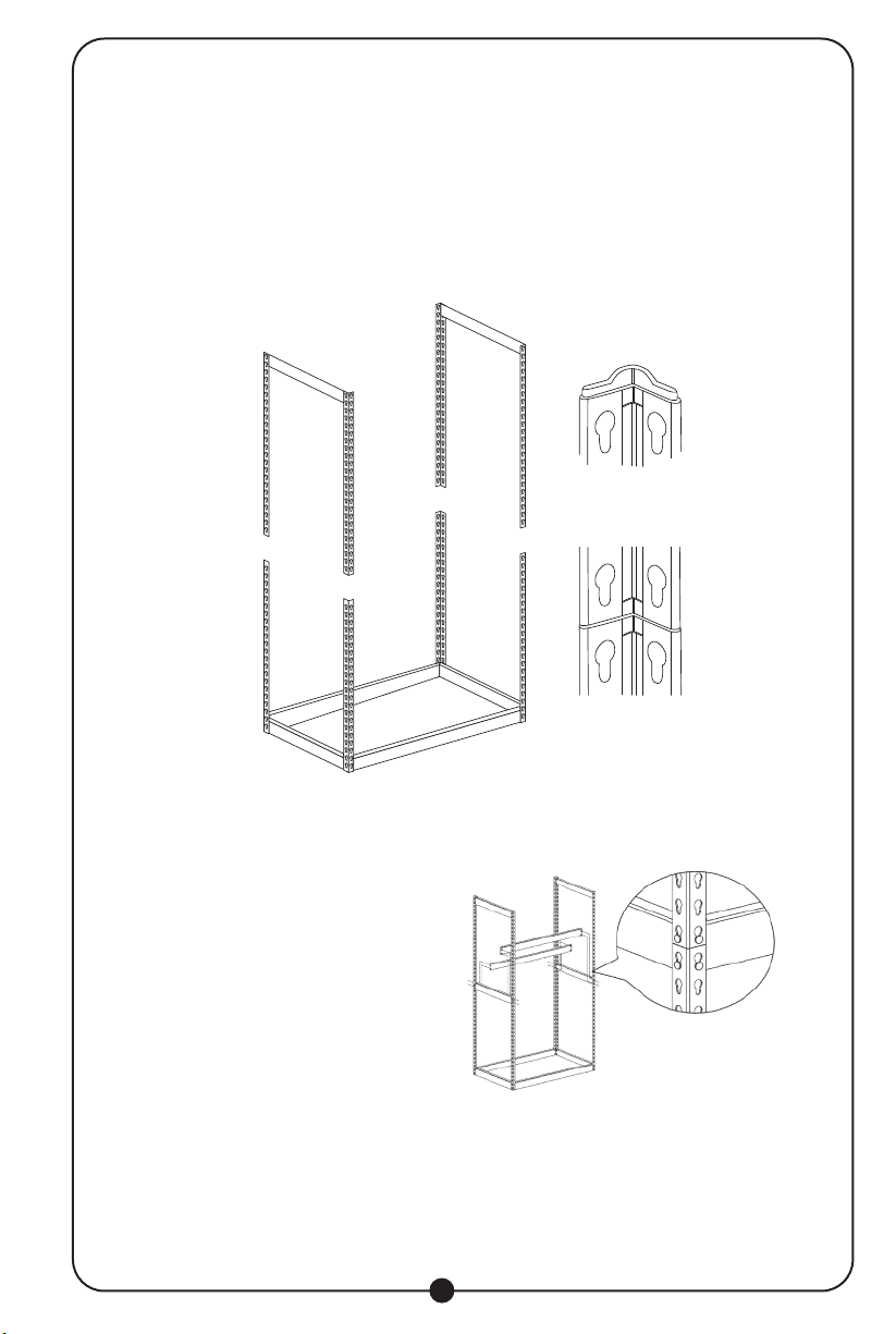
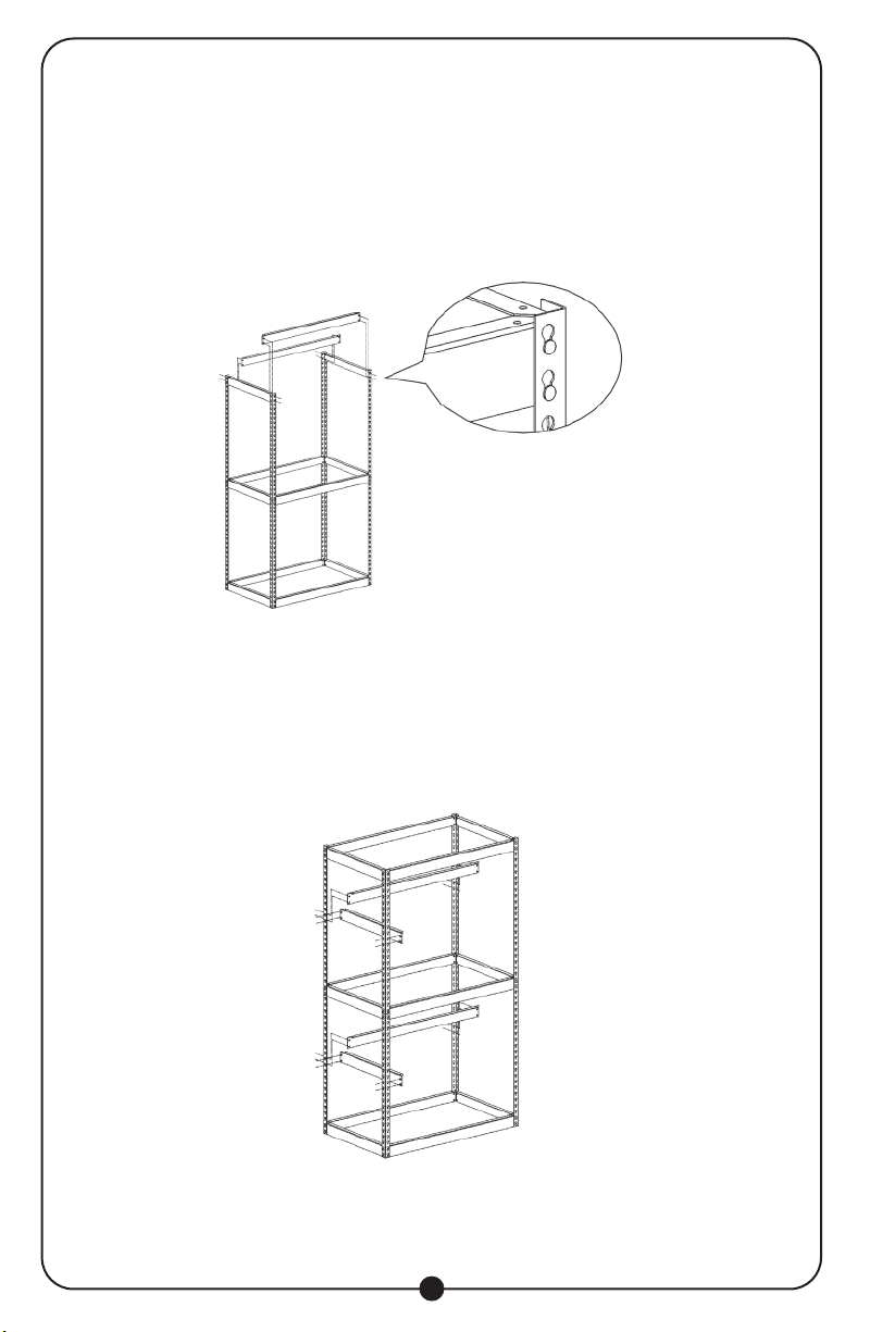
STEP 3
Start the top end assembly by joining a short double rivet beam into the top keyholes of
a corner post (detail A). Add the second corner post. Hit the beam close to joints to lock
pieces together.
11
STEP 4
Before joining the top assembly to the bottom frame assembly, insert the post joints
into the angle posts on the bottom frame assembly.
Repeat for the opposite top end assembly.
STEP 5
Add two long double rivet beams to
mid section as shown. Be sure to
use the bottom key hole of the top
assembly corner post and top key
hole of the bottom assembly. Follow
the proper keyholes as shown in
the detail illustration. Be sure to
have all rivets in the keyholes before
hitting the beam near the joints with a
rubber mallet to lock pieces together.
12
STEP 6
Add two additional Long double rivet beam to top two key holes of the corner post
as shown. Be sure to have all rivets in the keyholes before hitting the beam near the
joints with a rubber mallet to lock pieces together.
STEP 7
Assemble the remaining short and long double rivet beams to your desired location
on the corner post. Hit the beam neat the joints with a rubber mallet to lock pieces
together.
13
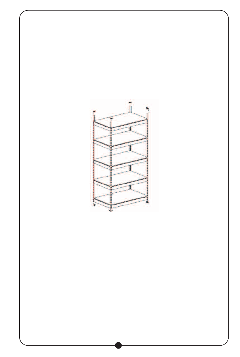
STEP 8
Add post caps to the bottom and top of the four corner angle posts.
Place the shelves into position. Slide shelves in at an angle, then position so they are
resting on the flanges.

Table of contents
Popular Indoor Furnishing manuals by other brands

Regency
Regency LWMS3015 Assembly instructions

Furniture of America
Furniture of America CM7751C Assembly instructions

Safavieh Furniture
Safavieh Furniture Estella CNS5731 manual

PLACES OF STYLE
PLACES OF STYLE Ovalfuss Assembly instruction

Trasman
Trasman 1138 Bo1 Assembly manual

Costway
Costway JV10856 manual


