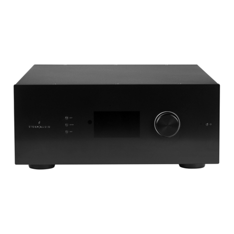
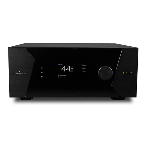
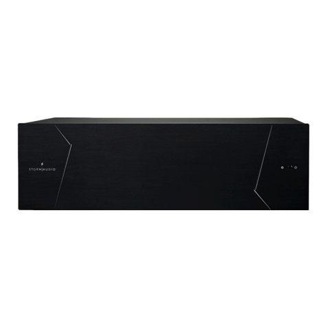
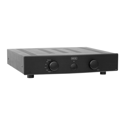
Storm Audio PA 8 ULTRA ELITE Assembly instructions

Multi-Channel Power Ampliers
PA 8 ELITE
PA 8 ULTRA ELITE
PA 16 ELITE
Read Me First... If you need
help...
1. Check the online help of the Web
Installer Interface.
3. Contact our support team:
support@stormaudio.com
2. Check our website support page.
Installer Guide

1
Welcome
Thank you for choosing a StormAudio
Multi-Channel Amplier. This guide
provides step-by-step instructions for
setting up your PA.
The PA range is based on a common
Class D technology delivering high
grade performance and sonical quality.
This guide will describe the connectivity
of each model.
What’s In the Box
Installer Guide
Safety Instructions
Multi-Channel
Amplier
Power cord *
* depending on the region, the power cord will be
delivered with Fuse to be installed

2
Before You Begin
1. In case the AC cord is delivered with Fuses attached, make sure to install them before
connecting the unit.
2. Ensure your electrical circuit has a good ground connection with all audio equipment
connected to the same ground node to avoid ground loop.
XLR cables
Multi-Channel
Amplier Speakers with cables
Mono Jack
3.5mm cables
3. Required equipment:
* the PA needs a DHCP server to be part of the network to get an IP address allocated.
Make sure to check your Internet Provider box or LAN/Switch box for router function.
Audio
Processor
LAN router
with Cat5/6 RJ45 cable *

3
The installation of the PA shall be made following below steps that will be described along
this guide.
Installation Flow
1Audio inputs and control connectivity
2
3
Audio outputs connectivity
4
Trigger control
5
Power Up and function description
6
Connectors description
Specications
4
7
10
11
14
15

Hardware Connections
Inputs
1PA 8 ELITE PA 8 ULTRA ELITE PA 16 ELITE
4
1
3
4
1. Check Fuse and install the proper Fuse if required.
2. Connect AC cord to Power Outlet (do not turn ON now)
3. Connect the RJ45 LAN Network cable to the router/switch
4. Connect your Analog inputs via XLR (see part 5 for connectors description)
1.2) Connect the unit as shown below.
1.1) The PA 8 ELITE is made of 2 Master Modules and 2 Slave Modules with the Power Supplies
located in the Master Modules. We recommend that most consuming speakers such as LCR
and Subwoofers should be connected to the Master Modules, that is to say:
Input/Output 1, 2, 5 and 6.
2

Hardware Connections
Inputs
1PA 8 ELITE PA 8 ULTRA ELITE PA 16 ELITE
5
3
5
1. Check Fuse and install the proper Fuse if required.
2. Connect AC cord to Power Outlet (do not turn ON now)
3. Connect the RJ45 LAN Network cable to the router/switch
4. Position the switch according to the required output mode: Normal or Bridged
5. Connect your Analog inputs via XLR (see part 5 for connectors description)
1.3) The PA 8 ULTRA ELITE oers the possibility to provide more power by bridging
its outputs. On a per pair basis, you can decide to bridge them.
When Bridging is required, change the position of the Switch (4) to Bridge and
make use of the inputs 1, 3, 5 and 7 (shown in orange below).
4 4 44
5
1
2

Hardware Connections
Inputs
1PA 8 ELITE PA 8 ULTRA ELITE PA 16 ELITE
6
3
4
1. Check Fuse and install the proper Fuse if required.
2. Connect AC cord to Power Outlet (do not turn ON now)
3. Connect the RJ45 LAN Network cable to the router/switch
4. Connect your Analog inputs via XLR (see part 5 for connectors description)
1.5) Connect the unit as shown below.
4
1.4) The PA 16 ELITE is made of 4 Master Modules and 4 Slave Modules with the Power Supplies
located in the Master Modules. We recommend that most consuming speakers such as LCR
and Subwoofers should be connected to the Master Modules, that is to say:
Input/Output 1, 2, 5, 6, 9, 10, 13 and 14.
1
2

Hardware Connections
Outputs
2PA 8 ELITE PA 8 ULTRA ELITE PA 16 ELITE
7
Connect your Analog outputs. We have used high quality binding posts supporting
«banana plug», wire up to 4.5mm² and fork. The connector is isolated to limit risk
of short between outputs.
2.1) Connect the unit as shown below. Make sure to follow the recommendation made
on part 1.1 about splitting the most consuming speakers in channels 1, 2, 5 and 6.

Hardware Connections
Outputs
2PA 8 ELITE PA 8 ULTRA ELITE PA 16 ELITE
8
Connect your Analog outputs.
We warn you to be careful with the connection at this stage. Depending on the Output
mode selected in 1.3, you must wire the outputs according to above description:
- in green is shown a Normal (Single Ended) connection,
- in orange is shown the wiring you must follow for the Bridged mode.
2.2) Connect the unit as shown below.
!
+
-
+ -
Note: when in Bridged mode, the output channel number is the one with the «+» connection.
In above illustration, the corresponding input is channel 3.
!
NORMAL MODE BRIDGED MODE

Hardware Connections
Outputs
2PA 8 ELITE PA 8 ULTRA ELITE PA 16 ELITE
9
1
2
Connect your Analog outputs. We have used high quality binding posts supporting
«banana plug», wire up to 4.5mm² and fork. The connector is isolated to limit risk
of short between outputs.
2.3) Connect the unit as shown below. Make sure to follow the recommendation made
on part 1.4 about splitting the most consuming speakers in channels 1, 2, 5, 6, 9, 10,
13 and 14.

Hardware Connections
Trigger Control
3
10
1. The PA can be controlled remotely by the StormAudio
ISP (Immersive Sound Processor) or an external controller
via its Trigger Input.
You must setup your controller Trigger output to 12V Active
Status. The PA will react to a rising edge to power up.
2. If you need to control several amplier units, you can daisy
chain the Trigger control. It is internally delayed by 2s between
Input and Output.
1
2
( )
-
( )
+
The Trigger interfaces use a standard
3.5mm mono jack connector. A wire as
shown herewith is recommended.

Power Up and
Function description
4Power Up Information Protections
11
4.1) Power up sequence.
1
2
1. Turn the Main Switch to ON (I) on the back panel.
2. Front panel LED will blink red few seconds and will then remain red, unit is
in Sleep Mode.
3. When in Sleep Mode, press the Power Button or activate the Trigger in your controller.
Unit will start blinking red for a few seconds before turning to green.
3

Power Up and
Function description
4Power Up Information Protections
12
4.2) The front panel LED is used to indicate statutory informations as well as protection
feedback.
4.3) The statutory informations are described in the table below :
Unit is Initializing
Unit is in Sleep Mode
From the Sleep Mode to On Mode and vice versa, the unit has to be initialized
and properly turned o. This only lasts for a few seconds with no sound.
In this mode the unit is turned o. It can be activated via the Triggers or the
the Network.
RED
Blinking
RED
Fixed
Unit is Upgrading The PA rmware can be upgraded over the Network. When this occurs, the unit
falls in a specic mode with no other activity possible.
Unit is in On Mode The PA is in its normal playback mode with no failure detected. GREEN
Fixed
GREEN
Blinking

Power Up and
Function description
4Power Up Information Protections
13
4.4) The PA range includes a set of protection mechanisms to ensure its best reliability. The system will react
to the following event:
- Fan Failure : An active cooling regulation is integrated powered by no less than 6 low noise
high speed capable fans. Although extremely reliable over the product’s life cycle,
we continuously monitor the fans for proper functioning.
- Overheat : In very extreme conditions such as high power demand in an extreme high
temperature environment, the heat dissipation can reach temperatures that can
harm the unit if not managed properly.
- Overcurrent : To prevent shortage at the output that can damage the amplier stages, the
output current is monitored continuously.
- Overvoltage : Amplier stages can be damaged in a few occasions. Overvoltage at the power
supply level is one of them. To prevent from failure to occur in such event, we are
monitoring the supply rails.
4.5) The Protection Mechanism is described in the table below.
Overcurrent / Overvoltage
Module malfunction
Unit Overheat
The unit will MUTE the channels that are showing the problem.
This will be released automatically.
An ambiant temperature sensor measures the internal temperature. If >60°C,
the unit will go to Sleep Mode. In case PA is controlled via Trigger, unit will
restart with T<55°C.
YELLOW
Blinking
YELLOW/RED
Chaser
Module Overheat Each amplier module is monitored for temperature. The unit will MUTE the
channels automatically when threshold is reached.
This will be released automatically.
FAN failure A FAN failure will not prevent the unit from working correctly.
Overheat protection might nevertheless be triggered more easily.
YELLOW
Fixed
YELLOW/RED
Chaser

Hardware Connections
Connectors description
5
Special care must be taken of for the cables, wires and connectors to be used with the PA.
Here is a description of the connectors pin out and recommendation for the wiring.
5.1) To connect the PA to an ISP or a processor,
you must use male to female XLR cables.
The connector in the PA is a Female XLR.
We recommend cables up to 3m.
5.2) In some cases, it might be required to connect to processors with unbalanced
outputs. In such case, the wiring should be done as shown.
14

Specications
6
PA 8 ELITE PA 16 ELITE
Amplifier Class Class D Class D
Channel configuration SE = Single Ended,
BTL = Bridged Tied Load SE - 8 SE - 16 SE - 8 (Normal) BTL - 4 (Bridged)
RMS 8 Ω: 1 kHz 0.2% distortion 200 W 200 W 200 W 800 W
RMS 8 Ω: 1 kHz 1% distortion 250 W 250 W 250 W 1000 W
Frequency response High : -3 dB CEM 50 kHz 50 kHz 50 kHz 50 kHz
Low : -3 dB CEM 10 Hz 10 Hz 10 Hz 10 Hz
Signal / Noise Ratio (A-Weighted) Referred to P-rated > 115 dB > 115 dB > 115 dB > 115 dB
THD (20Hz-20kHz), 1 Watt to -1dB max. power < 0,03% < 0,03% < 0,03% < 0,03%
Gain Standard 26 dB 26 dB 26 dB 32 dB
Damping factor > 400 > 400
Power Supply Voltage range 110V to 240V 110V to 240V
Type SWITCHING MODE SWITCHING MODE
Range selection Universal Universal
Casing
Home / Rack (removable ears) ✓ ✓
Size 3RU 3RU
PA 8 ULTRA ELITE
Class D
✓
3RU
SWITCHING MODE
Output power
2 channels driven
Output power
All channels driven
> 400
110V to 240V
Universal
RMS 8 Ω: 20 Hz - 20 kHz 0.2% distortion 200 W 200 W 200 W 800 W
Note: Specications are subject to change without notice
15
This manual suits for next models
2
Table of contents
Other Storm Audio Amplifier manuals
