Stormor Solo User manual

= Assemble in order indicated.
FAILURE TO FOLLOW INSTRUCTION WILL RENDER
SHELVING UNSAFE!
=
= Measure to ensure correct location.
1
Assembly Guide
STORMOR®Shelving Bays
with Solo, Mono or Duo Frame Types
✓
= Instruction applies to shelving with SOLO Frames.
= Instruction applies to shelving with MONO Frames.
= Instruction applies to shelving with DUO Frames.
M
S
D
Dispose of packaging materials responsibly.
Assemble and locate for use on a suitable level floor surface.
Allow adequate working area.
INFORMATION
Key to some Symbols used in this Assembly Guide
TAKE CARE DURING ASSEMBLY! -
when lifting, stretching and using tools.
In use, ensure shelving is loaded and used safely.
DO NOT EXCEED SHELF & BAY LOAD CAPACITIES.
INFORMATION
IF IN DOUBT ALWAYS CONTACT YOUR SHELVING SUPPLIER
READ THIS GUIDE THOROUGHLY BEFORE COMMENCING
ASSEMBLY AND RETAIN FOR REFERENCE.
The information contained in this booklet was accepted as correct at the date of publication. However, the manufacturer reserves the right to make any necessary changes, in line with
product development and improvement. No liability can be accepted for any inaccuracies or omissions, although every reasonable care has been taken to make this publication as
complete and accurate as possible.
STORMOR SHELVING IS DESIGNED & MANUFACTURED IN THE UK TO QUALITY MANAGEMENT SYSTEMS CONFORMING TO THE INTERNATIONAL STANDARD BS EN ISO 9001:2000.
Assembly should be undertaken by two competent people,
preferably suitably trained shelving installers.
Before commencing assembly, unpack carefully and check that
all components ordered are included.
Basic Tools: ‘ head’-type Screw Driver; 10mm socket or
spanner; Measuring Tape.
Assess for floor fixing - tall, narrow bays may require this to
ensure stability - refer to page 19.
+
PART NUMBER: SZASSYGUIDE. ISSUE 2. Revised 11.04
2150
50
50
650
50
50
800
50
50
950
50
50
1100
50
50
350
800
50
50
500
800
50
650
800
950 1100 1250 1400 1550 1700 1850
2450 2600 2750 2900
50
2000
50
50
50
800
800
50
950
800
2300
50
50
1100
800
50
50
800
350
800
50
50
800
500
800
50
50
800
650
800
50
50
800
800
800
3050
50
50
800
950
800
3200
50
50
800
1100
800
3350
50
50
800
800
350
800
3500
50
50
800
800
500
800
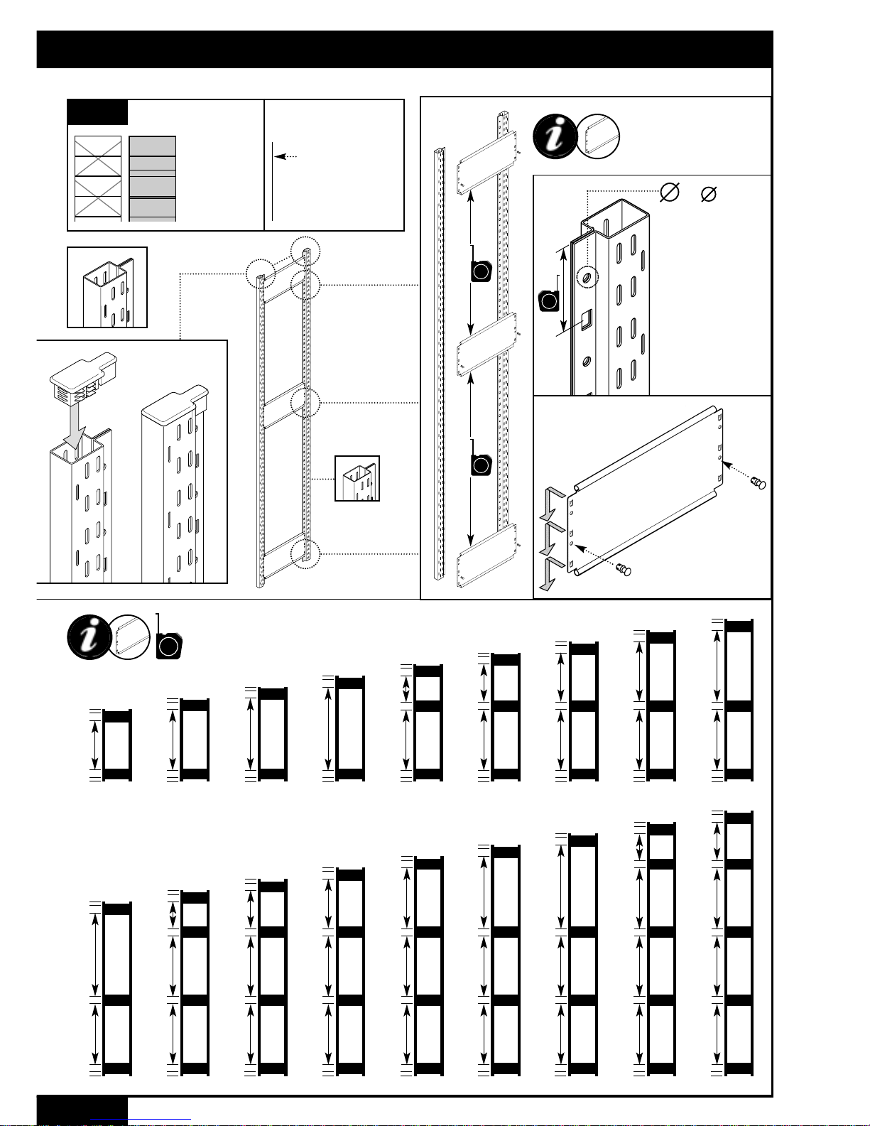
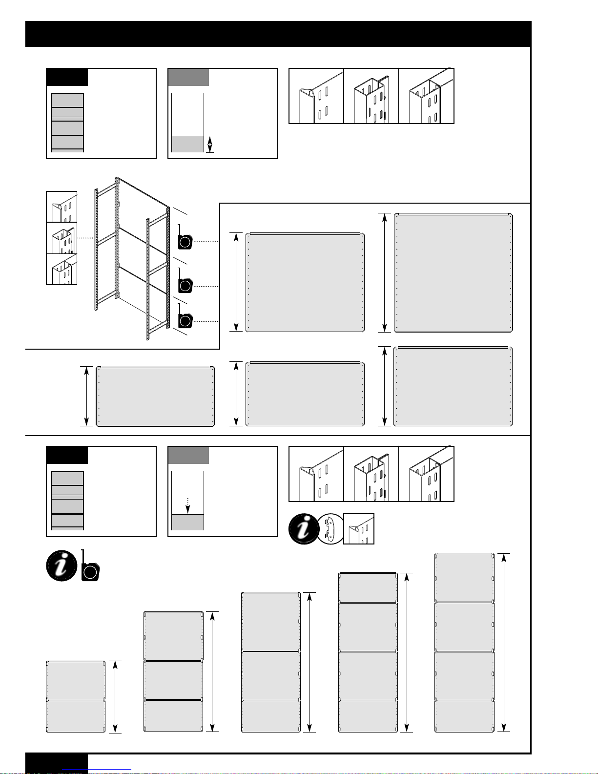
STORMOR®Shelving Bay Assembly
1Note: component illustrations are not to a constant scale. All dimensions are in mm
ALL MONO Frames with Clip-in Bracing
MONO
Frame
Assembly
OPEN BAYS
CLAD BAYS
1
M
M
✓✘
Bracing panel abuts
the larger hole in the
upright return flange -
plastic rivet is located
from this side
Opposite (smaller hole
face) of the flange is
identified by ‘dash’
marks scribed every
150mm
MONO FRAME
with Clip-in Bracing
50
2
700
850
100
850
850
1850 2150
400
850
850
2450
700
850
850
2750
850
1100
Identify
Frame
Type &
Orientation
OPEN BAYS
CLAD BAYS
2
Option of
Starter
End Frames
MONO standard height Frames
with Riveted Bracing
DUO two-part closed frame
MONO open frame
D
M
800
1100
650
800
1850 2150
950
800
2450
800
350
800
2750
800
650
800
MONO standard height Frames
with Clip-in Bracing
Note: component illustrations are not to a constant scale. All dimensions are in mm
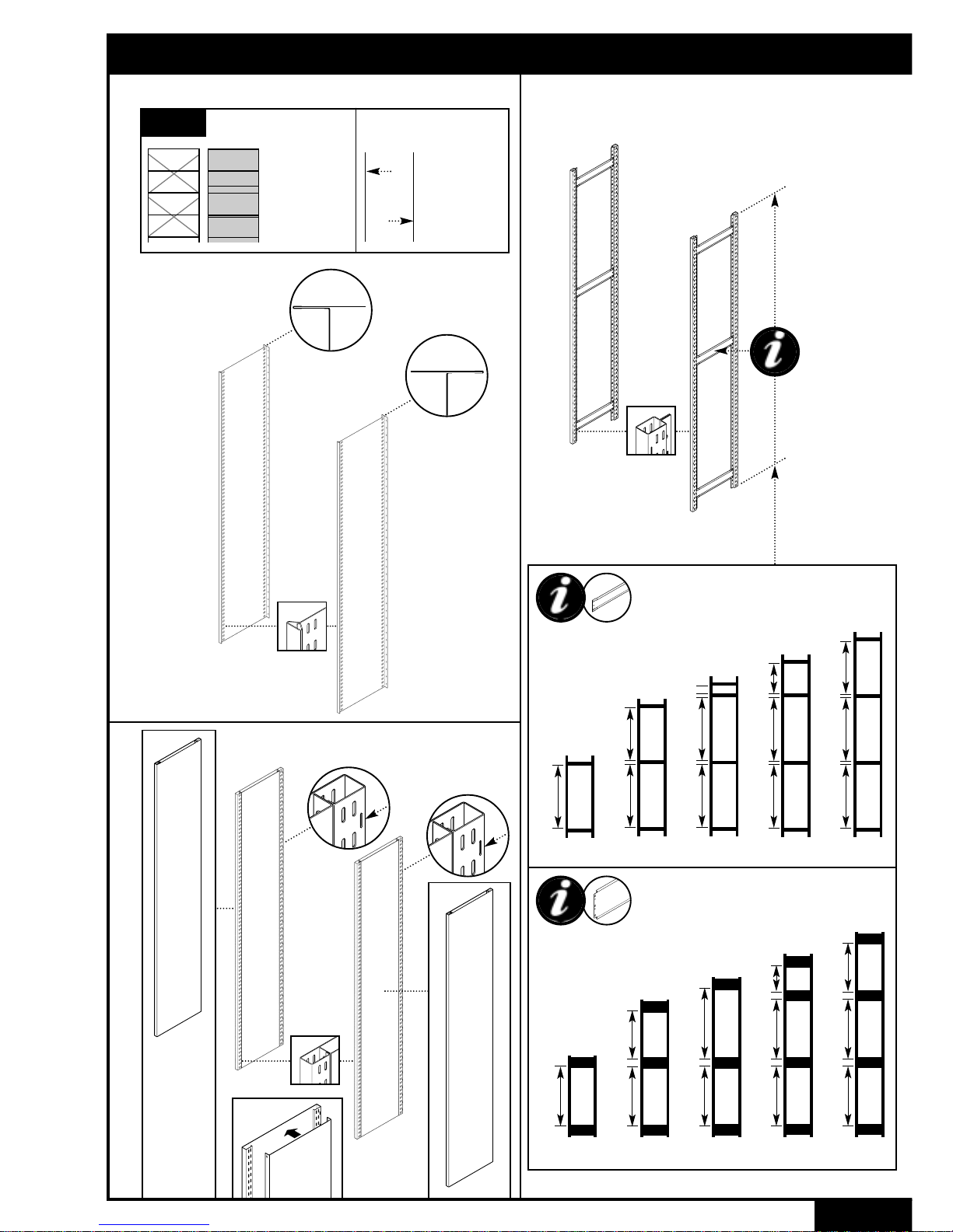
STORMOR®Shelving Bay Assembly
Check
Vertical
Orientation
SOLO single-part closed frame
S

125 750150750 75750150 125 600150600 75750150 125 600150450150600 75 125 750 75750150 125 750 225
OPEN
BRACED BAYS
3S
3.1A
Install
Cross-Bracing
SOLO
2750
1100
1850
2150
2450
Note: component illustrations are not to a constant scale. All dimensions are in mm
750
STANDARD
FRAMES
3
1
2
1
2
125
M6 x 10mm
M6 x 10mm
M6 x 10mm
S
S
STORMOR®Shelving Bay Assembly

125 750150750 75750150
OPEN
BRACED BAYS
3 3.1B D
M
✓
✓
✘
✘
125 600150600 75750150 125 600150450150600 75 125 750 75750150 125 750 225
Install
Cross-Bracing
MONO & DUO
2750
1100
1850
2150
2450
M6 x 10mm
M6 x 10mm
4
Note: component illustrations are not to a constant scale. All dimensions are in mm
STANDARD
FRAMES
125
750
2
D
M
1
STORMOR®Shelving Bay Assembly

5Note: component illustrations are not to a constant scale. All dimensions are in mm
125 750150750 75750150
125 600150600 75750150
125 600150450150600 75
125 750 75750150 125 750 225
2750
1100
1850
2150
2450
OPEN
BRACED BAYS
3 3.1B D
M
✓
✓
✘
✘
Install
Cross-Bracing
MONO & DUO
Backing bays
750
STANDARD
FRAMES
M6 x 10mm
M6 x 10mm
1
2
125
D
M
STORMOR®Shelving Bay Assembly

6
Note: component illustrations are not to a constant scale. All dimensions are in mm
125 750 75
0950
125 750 375
1250
125 450 75450300
1400
125 600 75600150
1550
125 600 225600150
1700
125 750 750150 225
2000
125 600150450150600 225
2300
125 750150750 225750150
125 75750150600150450150600
125 225750150600150450150600
125 75750150750150600150600
125 225750150750150600150600
3500
OPEN
BRACED BAYS
33.1C
Install
Cross-Bracing
ALL FRAME
TYPES
D
M
S
Brackets shown are omitted
in Solo Frame assembly
125 600150600 225750150
2600
2900 3050
3200 3350
S
EXTENDED FRAME RANGE - cross-bracing location
STORMOR®Shelving Bay Assembly
7
Locate Shelves
ALL FRAME
TYPES
OPEN
BRACED BAYS
3 3.3
D
S
M
Locate top & base, then
intermediate shelves
25
25
25
25
25
25
25
25
25
25
25
25
Floor Fixing!
ALL FRAME
TYPES
May be required for bay
stability - refer to page 19
OPEN
BRACED BAYS
3 3.2
Shelves share
common clips
S
1
2
3
4
Measure required shelf pitches
Note: component illustrations are not to a constant scale. All dimensions are in mm
STORMOR®Shelving Bay Assembly
>100

8
Locate Shelves
ALL FRAME
TYPES
OPEN
BRACED BAYS
3 3.3
11
2
LOCATE SHELVES WITH CARE
== +
✓✘
REMOVE SHELVES WITH CARE
==
✓✘
D
DO NOT EXCEED MAXIMUM SHELF PITCHES
>600
>600
>600
>600
>100
>900
>900
>900
>900
>100
M
>750
>750
>750
>750
>100
S
✓
=
ENSURE SHELF FLANGE IS LOCATED BETWEEN CLIPS
✘
3
Note: component illustrations are not to a constant scale. All dimensions are in mm
STORMOR®Shelving Bay Assembly

9
S
Extend To Build Runs
of Shelving
SOLO
OPEN
BRACED BAYS
3 3.4A
1 BAY
6 BAYS
8 BAYS
10 BAYS
9 BAYS
7 BAYS
2 BAYS 3 BAYS 4 BAYS 5 BAYS
S
Additional Bracing Frequency
Check Levels
Locate Base Plates to Level
Fix Down with Floor Clips
(where necessary)
Note: component illustrations are not to a constant scale. All dimensions are in mm
S
STORMOR®Shelving Bay Assembly
Incorporate Additional Bracing!
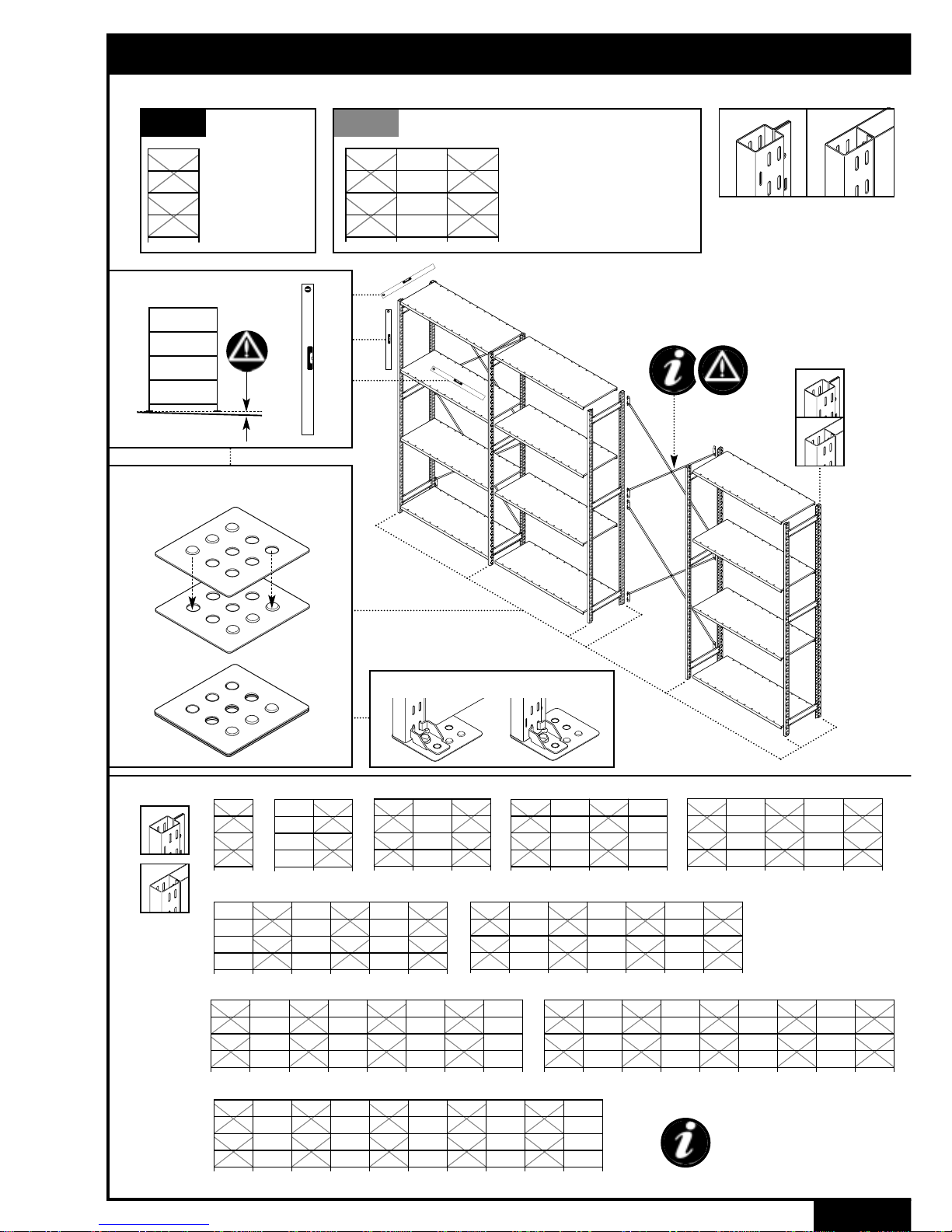
10
8 BAYS
10 BAYS
9 BAYS
Additional Bracing Frequency
Check Levels
Locate Base Plates to Level
D
D
M
M
D
M
6 BAYS 7 BAYS
1 BAY 2 BAYS 3 BAYS 4 BAYS 5 BAYS
Extend To Build Runs
of Shelving
MONO & DUO
OPEN
BRACED BAYS
3 3.4B
Fix Down with Floor Clips (where necessary)
D
M
Note: component illustrations are not to a constant scale. All dimensions are in mm
STORMOR®Shelving Bay Assembly
Incorporate Additional Bracing!

>125
>2000
>2000
>125
S
11
Rack Linking -
Back to Back Bays
SOLO
OPEN
BRACED BAYS
3 3.5A
BRACED FRAMES - link opposite (unbraced) side only
UNBRACED FRAMES - link both sides
S
12
Note: component illustrations are not to a constant scale. All dimensions are in mm
M6 x 10
STORMOR®Shelving Bay Assembly

12
D
M
Rack Linking -
Back to Back Bays
MONO & DUO
OPEN
BRACED BAYS
3 3.5B
>125
>2000
>2000
>125
No links
in outer face
of Duo
extension
frame
D
✘
✘
D
M
12
Note: component illustrations are not to a constant scale. All dimensions are in mm
Rack Link
✘
STORMOR®Shelving Bay Assembly
BRACED FRAMES - link opposite (unbraced) side only
UNBRACED FRAMES - link both sides
REAR CLAD
BAYS
4 4.1 D
M
Identify Panel
Heights
ALL FRAME
TYPES
S
REAR CLAD
BAYS
4 4.2 D
M
Identify Panel
Positions
ALL FRAME
TYPES
S
13
614 914
‘450’
‘900’
‘600’
464
D
S
M
764
‘750’
496
‘500’
Note: component illustrations are not to a constant scale. All dimensions are in mm
750
750
750
500
2750
750
450
750
500
2450
900
500
750
2150
600
750
500
1850
600
500
1100
Brackets shown are omitted
in Solo Frame assembly
S
STANDARD FRAMES
STORMOR®Shelving Bay Assembly

14
REAR CLAD
BAYS
4.2A4 D
M
Identify Panel
Positions
ALL FRAME
TYPES
S
450
500
0950
500
750
1250
900
500
1400
600
500
450
1550
500
600
600
1700
500
750
750
2000
900
900
500
2300
750
750
600
500
2600
900
750
750
500
2900
900
900
750
500
3050
900
900
900
500
3200
600
750
750
750
500
3350
750
750
750
750
500
3500 Brackets shown are omitted
in Solo Frame assembly
S
Note: component illustrations are not to a constant scale. All dimensions are in mm
EXTENDED FRAME RANGE
STORMOR®Shelving Bay Assembly

Note: component illustrations are not to a constant scale. All dimensions are in mm
450
750
500
600
900
REAR CLAD
BAYS
4
4.4A
Install
Rear Cladding
SOLO
S
M6 x 10mm
M6 x 10mm
M6 x 10mm
S
1
3
2
Nut & Bolt fixings
per panel
15
Floor Fixing!
ALL FRAME
TYPES
May be required for bay
stability - refer to page 19
4.3
REAR CLAD
BAYS
4
STORMOR®Shelving Bay Assembly
M6 x 10mm

Note: component illustrations are not to a constant scale. All dimensions are in mm
S
Extend To Build Runs
of Shelving
SOLO
4.4A
Locate Shelves -
refer to pages 7-8
4.5A
REAR CLAD
BAYS
4
1
2
3
1
2
3
1 2 3
1 2 3
S
●Note overlap of cladding sheets
●Nuts finger tight only until all cladding is assembled,
then fully tighten
CHECK LEVELS
Locate Base Plates to Level - refer to page 9
16
S
STORMOR®Shelving Bay Assembly

Note: component illustrations are not to a constant scale. All dimensions are in mm
17
D
M
M6 x 10mm
REAR CLAD
BAYS
4
4.4B
Install
Rear Cladding
MONO & DUO
450
750
500
600
900
M6 x 10mm
M6 x 10mm
Nut & Bolt fixings
per panel
D
M
3
2
1
M6 x 10mm
STORMOR®Shelving Bay Assembly

Note: component illustrations are not to a constant scale. All dimensions are in mm 18
Extend To Build Runs
of Shelving
MONO & DUO
4.4B
REAR CLAD
BAYS
4
1
2
3
1
2
3
1
Fully tighten nuts during assembly
CHECK LEVELS
Locate Base Plates to Level - refer to page 10
D
M
2 3
1 2 3
Locate Shelves -
refer to pages 7-8
4.5B
STORMOR®Shelving Bay Assembly
D
M
D
M

STORMOR®Shelving Bay Assembly
19
Floor Fixing
For Stability
ALL FRAME
TYPES
OPEN BAYS
CLAD BAYS
5
D
h
H
D
h
H
STABILITY = HEIGHT TO DEPTH RATIO
H:D > 4:1 = FLOOR FIXING RECOMMENDED
h:D > 4:1 = FLOOR FIXING RECOMMENDED
= Location of additional Floor Clips where H:D/h:D > 6:1
D = Depth
H = Height, floor to highest loaded shelf, with top shelf used as
a dust cover, unladen
h = height, floor to highest loaded shelf, with top shelf loaded
1
D
M
S
Floor Anchor
Floor Clip
2
✎
✎
✎
✎
✎
✎
6Nm
✎
4
35 min.
8
✎
✎
D
M
S
Ensure floor will
accept Anchor!
3
This manual suits for next models
2
Popular Indoor Furnishing manuals by other brands

Regency
Regency LWMS3015 Assembly instructions

Furniture of America
Furniture of America CM7751C Assembly instructions

Safavieh Furniture
Safavieh Furniture Estella CNS5731 manual

PLACES OF STYLE
PLACES OF STYLE Ovalfuss Assembly instruction

Trasman
Trasman 1138 Bo1 Assembly manual

Costway
Costway JV10856 manual


