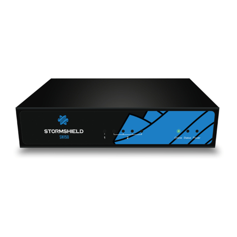
Stormshield SN200 User manual

TECHNICAL NOTE
STORMSHIELD NETWORK SECURITY
SECURE RETURN OPTION
Product concerned: SN150, SN160(W), SN200, SN210(W), SN300, SN310, SN500, SN510, SN700,
SN710, SN900, SN910, SN2000, SN2100, SN3000, SN3100, SN6000, SN6100, SNi20 and SNi40
Document last updated: August 1, 2022
Reference: sns-en-secure_return_option_technical_note

Table of contents
Introduction 3
Environment 4
Warning 4
Recycling 4
Required tools 4
SN150 5
SN200 and SN300 6
SN160(W), SN210(W) and SN310 7
SN500 and SN700 8
SN510, SN710 and SN910 9
SN900 11
SN2000 and SN3000 13
SN2100 and SN3100 15
SN6000 17
SN6100 19
SNi20 21
SNi40 24
Further reading 28
SNS - TECHNICAL NOTE
SECURE RETURN OPTION
Page 2/29 sns-en-secure_return_option_technical_note - 08/01/2022

Introduction
As part of the SECURE RETURN option, under certain conditions, Stormshield allows users to
remove and keep the data storage medium for confidentiality reasons.
This document sets out the phases associated with this operation for products in the
Stormshield Network range.
SNS - TECHNICAL NOTE
SECURE RETURN OPTION
Page 3/29 sns-en-secure_return_option_technical_note - 08/01/2022

Environment
Warning
The operations described in this document must only be performed by operators who have
been trained in the maintenance of products containing electronic cards, and having been duly
instructed by the user to do so.
Before performing any intervention, the operator must ensure in particular that:
lThe product is physically disconnected from the mains power supply,
lAll precautions have been taken to guarantee an ESD-safe (ElectroStatic Discharge)
environment.
Recycling
If the storage medium is approaching the end of its life cycle, it is the operator’s duty to comply
with existing recycling regulations.
Required tools
lA set of Phillips screwdrivers,
lA small flat screwdriver,
lA set of spanners for hex spacers.
SNS - TECHNICAL NOTE
SECURE RETURN OPTION
Page 4/29 sns-en-secure_return_option_technical_note - 08/01/2022

SN150
Data is stored in Flash memory on this product, in micro SD card format, installed on the
motherboard.
Dismantling
1. Using the Phillips screwdriver, unscrew the 3 black countersunk screws.
This operation will tear the warranty sticker.
2. Open the appliance.
You will see the micro SD card on the upper part of the motherboard, next to the 5 LEDs of
the front panel. It is held in place by a line of glue and a metal cover plate.
3. Using the small flat screwdriver, remove the adhesive strip by scraping lightly at it.
4. Unlock the metal cover by sliding it a few millimeters towards the rear of the product:
5. Open up the cover all the way.
6. Retrieve the micro SD card, turning the appliance upside down over the work area.
7. Place the appliance back in its previous position.
8. Close the cover.
9. Lock it by sliding it a few millimeters towards the front panel of the product.
Assembling
1. Put both parts of the appliance back together.
2. Close it up using the 3 screws.
SNS - TECHNICAL NOTE
SECURE RETURN OPTION
Page 5/29 sns-en-secure_return_option_technical_note - 08/01/2022

SN200 and SN300
On these products, data is stored on an internal Flash module.
Dismantling
1. Unscrew the 4 black countersunk screws with a Philips screwdriver.
2. Open the appliance.
This operation will tear the warranty sticker.
3. Locate the Flash module:
4. Unscrew the fastening screw of the Flash module with a Philips screwdriver.
5. To extract the flash module, pull it gently perpendicular to the motherboard:
Assembling
1. Ensure that the screw of the Flash module remains outside the chassis.
2. Put both parts of the appliance back together.
3. Close it up using the 4 screws.
SNS - TECHNICAL NOTE
SECURE RETURN OPTION
Page 6/29 sns-en-secure_return_option_technical_note - 08/01/2022

SN160(W), SN210(W) and SN310
On these products, data is stored on an internal Flash module.
Dismantling
1. Unscrew the 4 black countersunk screws (3 for the SN160) with a Philips screwdriver.
One of these screws covers the warranty sticker.
2. Open the appliance.
This operation will tear the warranty sticker.
3. Remove the strip of white glue.
4. To extract the flash module, pull it gently and perpendicular to the motherboard.
Assembling
1. Put both parts of the appliance back together.
2. Close it up using the 4 screws (3 for SN160).
SNS - TECHNICAL NOTE
SECURE RETURN OPTION
Page 7/29 sns-en-secure_return_option_technical_note - 08/01/2022

SN500 and SN700
On these products, data is stored on an internal hard disk.
Dismantling
1. Using the Phillips screwdriver, unscrew the 2 black countersunk screws located at the back
of the cover.
2. Remove the cover by sliding it backwards.
This operation will tear the warranty sticker.
IMPORTANT
Closely follow the instructions and precautions for handling the hard disk given in the vendor’s
installation guide.
3. Locate the hard disk.
4. Remove the adhesive strip from the hard disk.
5. Unplug the SATA connector.
6. Unscrew the 4 fastening screws of the hard disk with a Philips screwdriver:
7. Remove the hard disk & support setup.
8. Unscrew the 4 lateral screws of the hard disk.
9. Retrieve the hard disk.
Assembling
1. Put the support back on its 4 spacers, with the vibration absorbers in place.
2. Fasten the support with the 4 screws, by using one of them to fasten the free ring terminal
of the cable connecting the support + hard disk setup to the chassis.
3. Check that the 4 lateral screws of the hard disk remain outside the chassis.
4. Put the cover back in place and close it up using the 2 screws.
SNS - TECHNICAL NOTE
SECURE RETURN OPTION
Page 8/29 sns-en-secure_return_option_technical_note - 08/01/2022

SN510, SN710 and SN910
On these products, data is stored on an internal hard disk.
Dismantling
1. Using a Philips screwdriver:
lUnscrew the 2 black countersunk screws located at the back of the cover.
lUnscrew the 10 black countersunk screws that hold down the lateral fastening brackets.
2. Remove the cover by sliding it backwards.
This operation will tear the warranty sticker.
IMPORTANT
Closely follow the instructions and precautions for handling the hard disk given in the vendor’s
installation guide.
3. Locate the hard disk.
4. Remove the adhesive strip from the hard disk.
5. Unplug the SATA connector (SN510 and SN710) or the SATA connector and the hard disk's
power plug (SN910):
6. Unscrew the 4 fastening screws of the hard disk with a Philips screwdriver.
7. Remove the hard disk & support setup.
8. Unscrew the 4 lateral screws of the hard disk.
9. Retrieve the hard disk.
SNS - TECHNICAL NOTE
SECURE RETURN OPTION
Page 9/29 sns-en-secure_return_option_technical_note - 08/01/2022

Assembling
1. Put the support back on its 4 spacers, with the vibration absorbers in place.
2. Fasten the support with the 4 screws, by using one of them to fasten the free ring terminal
of the cable connecting the support + hard disk setup to the chassis.
3. Check that the 4 lateral screws of the hard disk remain outside the chassis.
4. Put the cover and fastening brackets back in place.
5. Close it up using the 12 screws.
SNS - TECHNICAL NOTE
SECURE RETURN OPTION
Page 10/29 sns-en-secure_return_option_technical_note - 08/01/2022

SN900
On this product, data is stored on an internal hard disk.
Dismantling
1. Using the Phillips screwdriver, unscrew the 2 black countersunk screws located at the back
of the cover.
2. Remove the cover by sliding it backwards.
This operation will tear the warranty sticker.
IMPORTANT
Closely follow the instructions and precautions for handling the hard disk given in the vendor’s
installation guide.
3. Locate the hard disk:
4. Remove the adhesive strip from the hard disk
5. Unplug the SATA connector.
6. Using the Phillips screwdriver, unscrew the 4 fastening screws from the hard disk support,
keeping the associated hex spacer in place with a flat wrench.
7. Remove the hard disk & support setup.
8. Unscrew the 4 lateral screws of the hard disk with a Philips screwdriver.
9. Retrieve the hard disk.
SNS - TECHNICAL NOTE
SECURE RETURN OPTION
Page 11/29 sns-en-secure_return_option_technical_note - 08/01/2022

Assembling
1. Put the support back on its 4 spacers, with the vibration absorbers in place.
2. Fasten the support with the 4 screws, by using one of them to fasten the free ring terminal
of the cable connecting the support + hard disk setup to the chassis.
3. Check that the 4 lateral screws of the hard disk remain outside the chassis.
4. Put the cover back in place.
5. Close the cover using the 2 screws.
SNS - TECHNICAL NOTE
SECURE RETURN OPTION
Page 12/29 sns-en-secure_return_option_technical_note - 08/01/2022

SN2000 and SN3000
On these products, data is stored on one or two SSDs accessible from the front panel.
Each SSD can be easily extracted: to unlock its tray, press on the gray button while pushing it
laterally towards the left.
Other data is stored on an internal flash module.
Dismantling
1. Unscrew the 9 black countersunk screws with a Philips screwdriver.
2. Open up the appliance by pushing the cover towards the back and removing it.
This operation will tear the warranty sticker.
3. Locate the Flash module:
4. Unscrew the fastening screw of the Flash module with a Philips screwdriver, by keeping the
associated hex spacer in place with a flat wrench:
SNS - TECHNICAL NOTE
SECURE RETURN OPTION
Page 13/29 sns-en-secure_return_option_technical_note - 08/01/2022

5. To extract the flash module, pull it gently and perpendicular to the motherboard.
REMARKS
This operation does not require the crossbar to be dismantled.
Assembling
1. Ensure that the screw of the Flash module remains outside the chassis.
2. Put the cover back in place.
3. Push it forward.
4. Close the chassis back up using the 9 screws.
SNS - TECHNICAL NOTE
SECURE RETURN OPTION
Page 14/29 sns-en-secure_return_option_technical_note - 08/01/2022

SN2100 and SN3100
On these products, data is stored on one or two SSDs accessible from the front panel.
Each SSD can be easily extracted: to unlock its tray, press on the gray button while pushing it
laterally towards the left.
Other data is stored on an internal flash module.
Dismantling
1. Unscrew the 13 black countersunk screws of the upper cover with a Philips screwdriver.
2. Open up the appliance by pushing the cover towards the back and removing it.
This operation will tear the warranty sticker.
3. Locate the Flash module:
4. To extract the flash module, pull it gently and perpendicular to the motherboard:
SNS - TECHNICAL NOTE
SECURE RETURN OPTION
Page 15/29 sns-en-secure_return_option_technical_note - 08/01/2022

5. If your SN3100 is equipped with a TPM (Trusted Platform Module), extract it by pulling it
gently and perpendicular to the motherboard:
Assembling
1. Put the cover back on.
2. Push it forward.
3. Close the chassis back up using the 13 screws.
SNS - TECHNICAL NOTE
SECURE RETURN OPTION
Page 16/29 sns-en-secure_return_option_technical_note - 08/01/2022

SN6000
On this product, data is stored on 2 SSDs accessible from the rear panel.
Each SSD can be easily extracted: to unlock its tray, press on the lever while pushing it laterally
towards the right.
Other data is stored on an internal SSD.
Dismantling
1. Unscrew the 4 fastening screws from the cover of the chassis with a Philips screwdriver:
l2 lateral countersunk screws on the rear of the product.
l2 pan head machine screws on the rear panel.
2. Open up the appliance by pushing the cover towards the back.
This operation will tear the warranty sticker:
3. Locate the SSD:
SNS - TECHNICAL NOTE
SECURE RETURN OPTION
Page 17/29 sns-en-secure_return_option_technical_note - 08/01/2022

4. Remove the adhesive strip from the power and data connectors on the SSD.
5. Unplug these connectors.
6. The SSD is mounted on a metal plate, fastened by 4 countersunk screws: remove these 4
screws.
7. Lightly lift the back of the metal plate, and pressing against the front part of the SSD, extract
the whole setup by pushing towards the back of the chassis.
8. Extract the SSD by removing the 4 countersunk screws under the SSD:
Assembling
1. Place the metal plate back into its notches:
2. Push it towards the front of the chassis.
3. Fasten it using the 4 screws.
4. Ensure that the 4 fastening screws of the SSD remain outside the chassis.
5. Put the cover back in place and push it forward.
6. Close the chassis back up using the 4 screws.
SNS - TECHNICAL NOTE
SECURE RETURN OPTION
Page 18/29 sns-en-secure_return_option_technical_note - 08/01/2022

SN6100
On this product, data is stored on 2 SSDs accessible from the front panel.
Each SSD can be easily extracted: to unlock its tray, press on the lever while pushing it laterally
towards the right.
Other data is stored on an internal flash module.
Dismantling
1. Unscrew both of the thumbscrews that fasten the top cover, located on the rear panel of the
SN6100:
2. Open up the appliance by pushing the cover towards the back.
This operation will tear the warranty sticker.
3. Locate the flash module:
4. The flash module is fastened with one screw; remove it.
SNS - TECHNICAL NOTE
SECURE RETURN OPTION
Page 19/29 sns-en-secure_return_option_technical_note - 08/01/2022

5. Extract the flash module:
6. Screw the fastening screw of the flash module back in its spacer.
Assembling
1. Put the cover back on.
2. Push it forward.
3. Close the chassis back up using the 2 turnscrews.
SNS - TECHNICAL NOTE
SECURE RETURN OPTION
Page 20/29 sns-en-secure_return_option_technical_note - 08/01/2022
This manual suits for next models
21
Table of contents
Other Stormshield Network Hardware manuals
Popular Network Hardware manuals by other brands
Broadcast Tools
Broadcast Tools WebSwitch Installation and operation manual
ADTRAN
ADTRAN TSU 120 user manual
Avocent
Avocent MergePoint 5240 brochure
Paradyne
Paradyne 8540 Network configuration guide
Allied Telesis
Allied Telesis CentreCOM AT-3606F installation manual

Aviat Networks
Aviat Networks ECLIPSE IDU GE3 16x Product description
