Strässle & Co DT80 T Quick guide

issue V8.3E from 01.07.2019
1
Operating and safety instructions
vacuum system DT80 T
Strässle & Co.
Medizintechnik GmbH
Primelweg 5
D-72461 Albstadt
Tel.: +49 (0)7432 - 220186
Fax: +49 (0)7432 - 220189
Email: [email protected]
www.straessle-co.de
Item # 1000.507
issue V8.3E from 01.07.2019
2
Device symbols
This manual is protected by copyright law. Copying, reproduction and translation in any form –including excerpts –is forbidden.
The mentioning of other producer’s products in this manual serves exclusively as a piece of information and is no violation against
the trademark protection law. Strässle & Co
I
O
Follow instructions for use
This part falls under classification CF with defibrillation protection
This part falls under classification BF
ON Power switch: Power on
Remote control: Switch vacuum system to stand-by mode
and release vacuum
Freigabe des Unterdruckes
OFF Power switch: Power off
Remote control: Switch off vacuum system
Vacuum levels
1
2
3
4
This part falls under classification BF with defibrillation protection

issue V8.3E from 01.07.2019
3
1DT80 General description
2Components
2.1 Construction and function of the vacuum electrodes
2.2 Construction and function of the distributor
2.3 Construction and function of the support arm
2.4 Construction and function of the vacuum system
2.5 Construction and function of the control unit
3Installation
3.1 Installation of the support arm clamping device
3.2 Connecting the vacuum system
3.3 Connecting the distributor and the vacuum lines
3.4 Operation
4Technical appendix
4.1 General information
4.2 Transport and storage
4.3 Operating conditions
4.4 Cleaning and disinfection of the vacuum electrodes
4.5 ECG plug-in cable
4.6 Maintenance intervals
4.7 Specifications
4.8 Scope of delivery
4.9 Warranty
5Safety instructions
5.1 Installation site
5.2 Cleaning / disinfection
5.3 Disposal of discarded DT80 suction devices
5.4 General information
TABLE OF CONTENTS

issue V8.3E from 01.07.2019
4
The DT80 vacuum system is a medical product according to guideline 93/42/EWG. It is
designed for operation with common ECG devices and offers improved safe ECG diagnostics
combined with increased economical efficiency.
The DT80 vacuum system suits for ECGs in rest as well as under physical exercise. Owing to
the secure fixing of the electrodes it is especially advantageous in ergometry.
The DT80 vacuum system is well suited for the practicing physician for “regular”use in
maximal 5 Exercise ECG or 20 Resting ECG per day. The system is not designed for high-use
ECG practice and continuous operation.
The vacuum electrodes are to be used according to standard measurement procedures. They are
fixed to the patient's body by means of a defined vacuum.
The DT80 vacuum system is qualified for ECG diagnostics of adults, teenagers and children
from the age of about 7 years (depending on body size).
Note
The DT80 vacuum system is dedicated only for using in hospital and in medical practice.
The DT80 vacuum system is not designed for continuous cardiac and circulatory monitoring
and emergency medicine.
The DT80 vacuum system is designed for temporary applications.
These operating instructions are considered to be a constituent of the device and are to be kept
therewith.
Exact observance of the operating instructions is a prerequisite for the proper operation of the
device and thus for the operator's safety.
Compliance with the safety instructions provides protection against injury and prevents undue
operation of the device.
Each user of this device or each person concerned with installation, maintenance, testing or
repair of the device should have completely read and understood these operating instructions
before they start working.
Appropriate juridical regulations of the MPG and the MPBetreibV are to be kept.
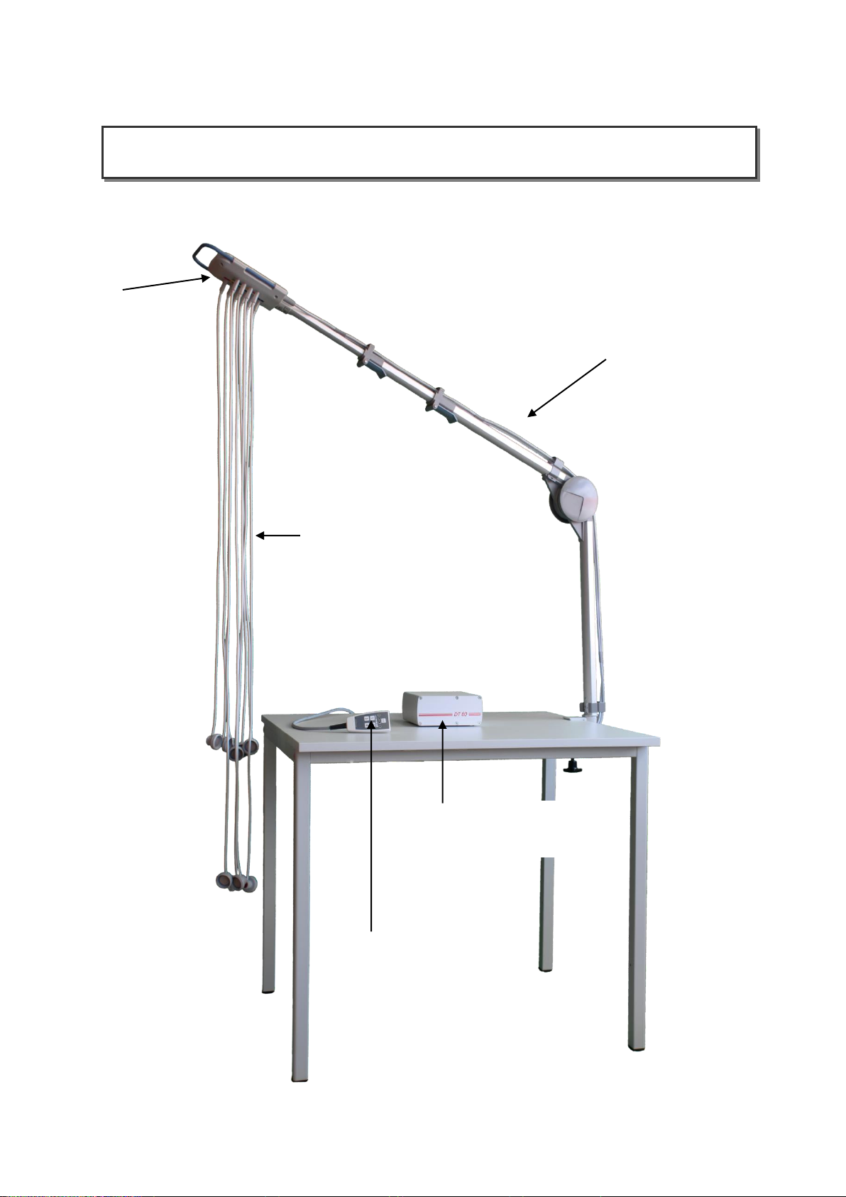
1. DT80 vacuum system
issue V8.3E from 01.07.2019
5
2.1 electrode cables
(application part)
Item # 4000-002 electrode 1m
Item # 4000-004 electrode 1,3m
Item # 2000-159 code plate set
2.3
support arm
Item # 3000-178
2. Components
2.4 vacuum unit
Item # 3000-205
2.2
distributor
Item # 3000-177
2.5 control unit
(integrated in vacuum unit)
issue V8.3E from 01.07.2019
6
2.1 Electrode cables (application part)
Ten electrode cables, that are R, L, N, F and C1 to C6, constitute the adaptation unit. A specially designed
combined electrode head, self-locking and equipped with a silver/silver-chloride electrode opens and adheres to
the patient's body on slight finger pressure.
2.2 Distributor
The so-called distributor, the topmost part of the support arm, holds the electrodes in such a way that they cannot
be connected improperly. Labels show the assignment of plugs and sockets.
2.3 Support arm
The support arm, a swivelling, telescopable positioning device, provides a high degree of comfort. Equipped with
a central swivel joint, the support arm can easily and quickly be fixed in any position required.
2.4 Vacuum unit
The vacuum unit of the DT80 controls the required vacuum level. A robust vacuum pump including an adapted
pressure vessel provides the selected pressure level. A special microprocessor control unit provides for coordinated
control of the overall function. Power socket, on/off switch, vacuum connector and the socket for the control unit
are located at the rear of the vacuum unit.
2.5 Control unit
The DT80 comprises a control unit which is connected directly to the vacuum unit. Equipped with an ON/OFF
button and four buttons for pressure levels as well as four light emitting diodes, the control unit enables functional,
informative and easy handling of the device.
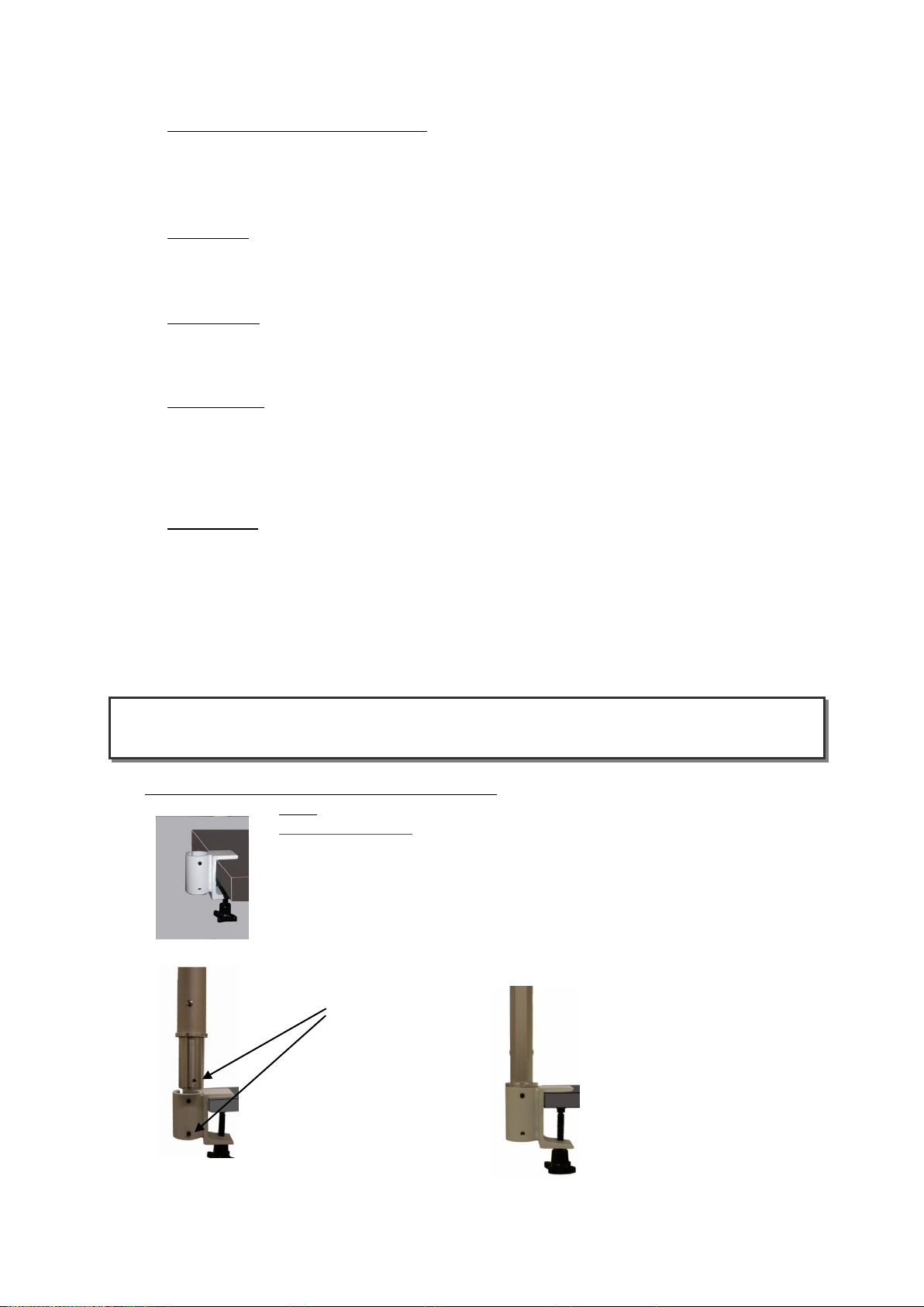
3.1 Installation of the support arm clamping device
Note: Proceed similarly with other clamping devices.
Safety information:
Ensure there is a secure connection when mounting the clamping device
for the support arm so that the connection will not come loose! Collisions
with other devices are to be excluded.
Fix clamping element at the desired position.
Insert support arm into the support device.
Please note!
Bores must match!
3. Installation

issue V8.3E from 01.07.2019
7
The threaded hole at the foot of
the support arm must match the
lower threaded hole of the
clamping device.
Turn in the grub screw (M6x10)
flush with the exterior of
the clamping device.
Do not tighten the screw!
When correctly assembled,
the support arm can be
rotated easily but
cannot be pulled out.
Note: The arm should be moveable without blockade by pin 1.
Together with the pressed foot of the arm by pin 2 results a swiveling unit
with excerpt protection.
3.1.1 Connecting the patient cables to the ECG device
Only CE marked devices may be connected
(see also operating instructions ECG)
3.2 Connect the vacuum unit
plug in
vacuum hose plug in
power cable
(If you want to remove the vacuum hose,
push back the ring of the vacuum hose
elbow connector, in order to pull off the
hose. )
bottom of the device bottom of the device
For a secure fixing in mobile
operation we recommend
replacing the stands with a
Velcro tape fixation. Stands and
Velcro tape are adhesive und
thus easily replaceable without
tools.
1
2
Tighten the upper grub screw (M6x6)
so that the foot of the support arm
presses firmly against the clamping
device.
[example]

issue V8.3E from 01.07.2019
8
3.3 Connecting the distributor and the vacuum lines
Note: To disassemble the system, the instructions of chapter 3.3 to 3.1
have to be executed in reversed order!
distributor
support arm
attach the distributor at the arm
When attaching the distributor a clicking
must be heard. Only in that case the
distributor is attached securely.
Note: With excessive pulling of the
distributor he becomes separated from
the support arm, in order to protect
the construction against to large lever
forces.
Plug in the vacuum lines into the delta distributor sockets as indicated by the codes.
Attach the plug-in brackets.
The patient´s cable is led with the help of the plug-in brackets along the support arm.
Fix the clips for
cable adjustment
on the profile rails.

issue V8.3E from 01.07.2019
9
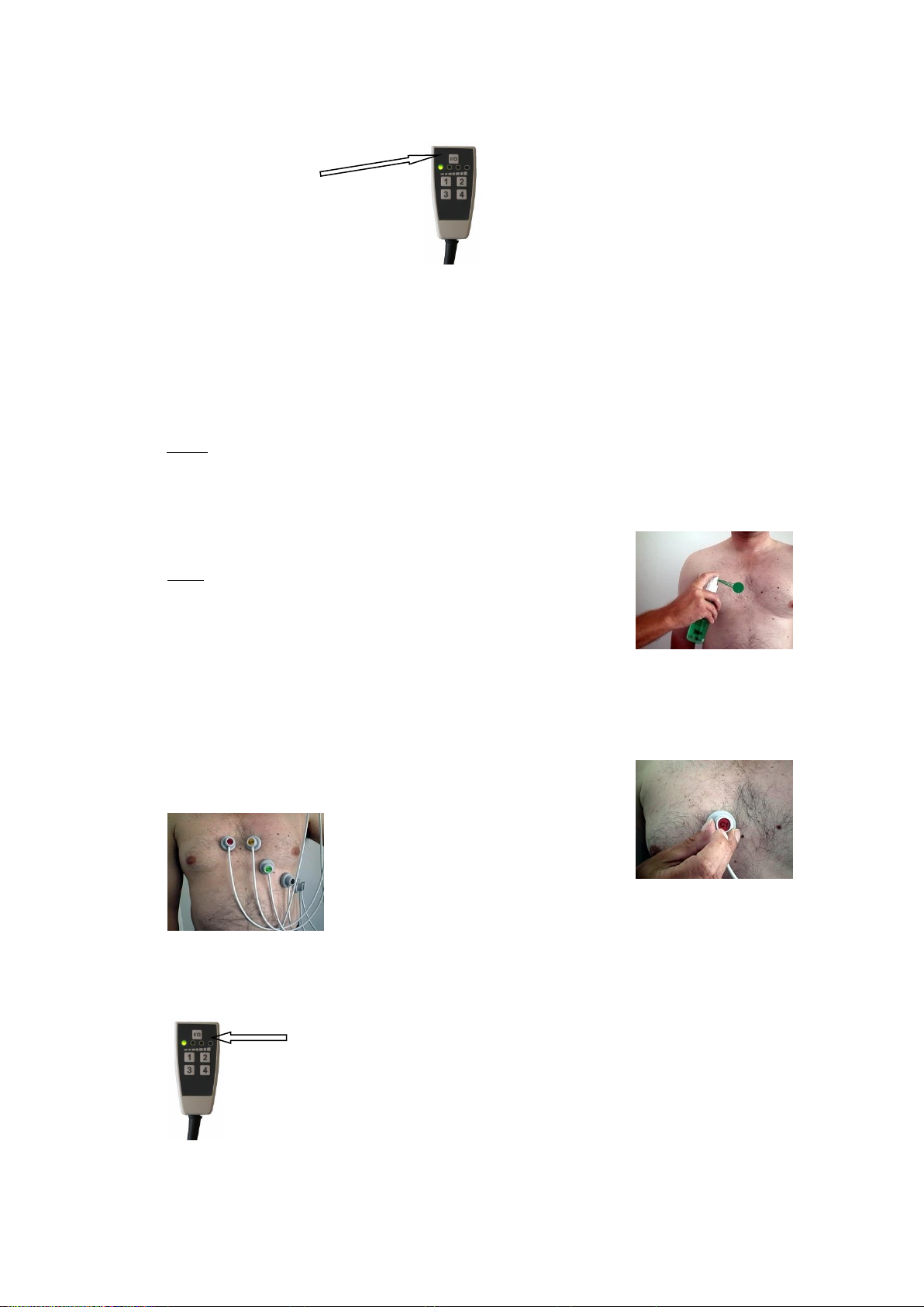
3.4 Operation
Press power switch to switch
on the vacuum unit
(green light will turn on)
3.4.1 Operation - Starting
Push the ON/OFF button at the control unit to start operation.
All LEDs of the control unit will be lit. Simultaneously, the blow-out
mode will be triggered for approximately 5 seconds.
Air will be blown through the electrodes with increased power
in order to remove any residual moisture.
Starting at the highest pressure level, the LEDs will turn off
subsequently, until all but the one for the lowest pressure level
are off. Alternating flashing of the LED associated with the selected pressure level
and simultaneous flashing of the remaining LEDs will signal general readiness of the device.
3.4.2 Position the support arm as desired
a) move up the arm b) move the arm downward
Note:
The support arm should be adjusted to a position in which
-the patient will not collide with the support arm
-the electrodes can be applied without tension
-the vacuum lines will not be bent
open the flap, position the telescopic arm,
close the flap
b) Example for a lower arm position:
Simply push down the arm until the desired
position is reached.
a) Example for a higher arm position:
When moving up the arm, a clicking in
regular intervals is heard. These are the rest
positions for the vertical adjustment of the
arm (if the arm is completely pulled out, it
automatically can drop maximally to such a
position!).
issue V8.3E from 01.07.2019
10
3.4.3 Switch on the vacuum
a) b) Pressure level 1 LED will turn on
Press the I/O
button to release
vacuum
Select vacuum level.
Press the appropriate key to select a vacuum level.
The selected vacuum level will be displayed by light emitting diodes.
Pressure allocation (standard programming)
Level 1 for smooth skin
Level 2 for slightly hairy skin
Level 3 for moderately hairy skin
Level 4 for very hairy skin
Note:
The lower the vacuum level selected, the better it will be tolerated by the skin.
(Look at safety instructions)
3.4.4 Applying the vacuum electrodes
First, spray individual spots with electrode spray on skin.
Note -Use only Signa Spray.
-Spray only individual spots, in order to prevent
short circuits between electrodes.
-The electrodes may only be applied to unwounded intact skin.
-Conductive parts of the electrode leads and connected plug-in devices of the
application parts, including the electrode, must not touch other conductive
parts, including earth!
The electrodes are applied by touching the code plates.
This will switch on the vacuum at the electrode.
In order to ensure artefact-free measurement, take care
that there is no tension acting on the electrode lines
when applying the electrodes.
3.4.5 Switch off the vacuum
To switch off the vacuum press the I/O button.
Subsequently the blow-out feature will be started.
-The electrodes will go off automatically.

issue V8.3E from 01.07.2019
11
3.4.6 Stand-by operation restored (status 3.4.3)
Stand-by operation is maintained for 30 minutes. If the system isn't restarted within this
period, the sleep mode will be activated (status 3.4.1.).
After interruption of the supply network, the system also falls into sleep mode.
3.4.7 particularities
The system is very quiet and can easily be "overheard". The DT80 has a run time
shutdown to protect its main components, which will operate after 90 minutes of non-
operation of the keypad.
Another special feature is the integrated temperature-backup mode. If the device
overheats due to excessive use, a temperature sensor will reduce the suction power until
the pump has cooled down sufficiently. On the control panel, this status is indicated by
flashing the respective set pressure level.
4.1 General information
The device is suitable for continuous operation.
Integrated defibrillation protection protects subsequent devices.
High-frequency fields and emissions may influence the quality of the ECG measurements.
The DT80 ECG vacuum unit is provided with a CE label according to the guideline given by the
Council on Medical Products 93/42 EWG and meets the basic requirements of Annex VII of the named
guideline.
The CE label includes only accessories listed in the accessory list.
4.2 Transport and storage
Ambient temperature range -40 degrees C to +70 degrees C
Relative humidity range 10% to 80%
Atmospheric pressure range 500 hPa to 1060 hPa
4.3 Operating conditions
The device is operable in the following ambient conditions:
Ambient temperature between +10 degrees C and +40 degrees C,
relative humidity between 30% and 75%, atmospheric pressure between 700 hPa and 1060 hPa.
4. Technical appendix

issue V8.3E from 01.07.2019
12
4.4 Cleaning and disinfection of vacuum electrodes
The surface of the vacuum electrodes must not be scratched or damaged. The surface cleaning is done by spraying
the alcohol disinfectant after each use (and maybe cleaned with a cleaning cloth)
For safe disinfectant to the manufacturer's instructions, especially the required exposure times, are observed. The
number of cleaning cycles under operating conditions has no negative impact on durability. Cleaning increases the
life and ensures consistently good signal.
quick disinfection and cleaning cloths (100 pcs.) Item # 1000-352
250ml quick disinfectant and detergent Item # 1000-354
5l quick disinfectant and detergent Item # 1000-351
750ml disinfectant foam Item # 1000-327
External spraying of
the hoses and suction
cups
Use of wipes from
the dispenser
External cleaning of
the hoses and suction
cups with wipes
Spray of the inside
of the electrode
Clean the sealing lip
and the electrode
surface with wipes
1.
2.
3.
4.
5.

issue V8.3E from 01.07.2019
13
4.4.1 Chemical-thermal disinfection
In the case of suspected contamination, the used vacuum lines should immediately be submitted to chemical-
thermal disinfection. With it, the vacuum lines will be submitted to a validated process of exterior and interior
cleaning/disinfection (for informations please ask the manufacturer).
4.5 ECG plug-in cable
The plug-in connector of the ECG plug-in cable at the support arm is connected to the ECG standard connector.
Other ECG devices are connected via adapters.
4.6 Maintenance
The devices should be checked (STK) according to the latest instructions given by the manufacturer at intervals of
2 years or after repair (or after intervention in the device). The check should be carried out by persons authorized
by Strässle & Co Medizintechnik GmbH. The exchange of fuses on the power supply should be effected only by
qualified personnel. Disconnection from the mains is compulsory. The power cable must be disconnected! No
other fuses than 2 x 0,315AT are allowed.
No service or maintenance should be performed while the unit is being used on a patient.
4.7 Specifications
Medical product class I (93/42/EWG)
Supply voltage 230V~ 50Hz
Rated consumption 22VA
Vacuum range 60hPa - 200hPa
Protection class I
Protection type IP 40
Degree of protection BF (supporting arm BF or CF defibrillation protected)
Dimensions 162x190x75 (w x l x h) vacuum unit only
4.8 Scope of delivery (depending on model version)
Power cable (1000-099) - removable part
Vacuum unit with control unit (3000-205)
Holder for control unit (2000-237) - accessory
Distributor (3000-177)
Support arm (3000-178)
Clips for cable adjustment (1000-596-2) - accessories
Electrode set 6x1m / 4xEXT 1,3m (4000-005) - removable parts
(alternatively electrodes 10x1m or 10x1,3m) (4000-001 or 4000-003) - removable parts
Electrode spray (1000-158) - accessory
Velcro fastening strips (2000-463) - accessories
optionally with mounting kit (various mounting kits possible) - accessories
4.9 Warranty
Strässle & Co. Medizintechnik GmbH grants warranty according as stated in the terms for sales, delivery, and
payment. Wearing parts and disposable material are not included in warranty.
Warranty will lapse in case of
damage caused by improper operation and undue usage.
inaccurate assembly, actions taken by unauthorized personnel, or use of accessories, disposable material or
replacement parts which are not original parts of Strässle & Co. Medizintechnik GmbH.
changes, extensions, repairs or actions whatsoever effected by persons not authorised by the manufacturer.
the electrical installation of the location where the device is connected not complying with the requirements
according to VDE 0107.
using the device disregarding the operating instructions.
Even after warranty has expired, original parts and accessories of the manufacturer should be used. Only thereby safe
and proper operation canbe ensured, as these products are continually improved and optimized.

issue V8.3E from 01.07.2019
14
The device should be operated only with a functioning mains supply according to VDE 0100-710, or applicable regulations, respectively.
The device is assigned to group 1 (medical equipment-ECG) according to VDE 0100-710.
In order to avoid electrical shock hazard, the device should be connected only to a mains supply with a protective conductor. It should not
be used with a mains supply with protective disconnector.
Installation is to be performed by qualified personnel authorized by the manufacturer.
When assembling the vacuum system, please ensure that you comply with the relevant provisions set out in the accident prevention
regulations and in Paragraph 9 of the EN60601-1 Standard (Protection from mechanical hazards from ME equipment and systems) when
mounting the supports. This applies in particular to the mounting of supports that are not original supports produced by Strässle & Co.
Medizintechnik GmbH as well as to the combination of Strässle & Co. Medizintechnik GmbH products with those of other
manufacturers.
If problems arise during installation or operation of the device, contact your dealer.
The main switch serves an all-conductor disconnector.
The device should be operated only by instructed technical personnel and must be documented.
The instructed personnel should check the system optical and functional for each using.
The device must complete undamaged and functional to be operated in only.
The distributor must be locked in the arm to prevent a self-acting release from the support arm (see 3.3)
By mounting error, improperly performed repair, improper modification and the use of third party products (screws, plugs, connectors,
etc.) it may due to imperfect fit to shear or abrasion, and ultimately solve coming of fortifications, to ensure defibrillation protection.
Improper repairs, improper modifications or non-use of original spare parts and original accessories will affect the protection of the
medical equipment used when unloading a defibrillator.
In the presence of visible damage, stiffness, etc. the supporting arm must be checked by trained personnel
Only original accessories and original replacement parts should be used. The device may only be operated with an original mains cable.
Replacement parts should be disposed in an environmentally beneficial way.
Modification of this device is not allowed without prior consent by the manufacturer (Strässle & Co. Medizintechnik GmbH).
Electrodes may not be brought in contact with oxidising acids or Cyanid solutions.
The specifications of vacuum level under 3.4.3 are to be kept. Too highly selected vacuum levels can lead to blisters on the skin.
To protect the skin, especially sensitive patients, who are repeat measurements with the same absolute placement of the electrodes are to
be avoid, without adequate recovery period 48h or after medical judgment.
Operation in conjunction with HF surgical devices is only permissible if the connected ECG device is suitable for this (see the operating
instructions for the ECG device).
When used in conjunction with an EEG device, the connected EEG device must be able to withstand 110V input voltage in the event of
defibrillation.
If several devices are connected to each other, the summation of leakage currents can lead to a potential hazard.
5.1 Installation site
The device may only be operated in medical rooms.
The device should not be operated in locations where explosions might occur.
The device should be installed in conditions where it is not exposed to excessive smoke, dust, shock, humidity, temperature changes or
direct solar radiation. An adequate distance should be kept from other devices, such as computers, monitors, etc.
The device should be installed at a place where it can´t be climbed or sit upon.
5.2 Cleaning
Before cleaning, press the I/O button to switch off the DT80 vacuum system and disconnect the power cable.
The device should be cleaned with a soft cloth which is moistened only slightly with water. Never use scouring agents, benzene, thinner, or
similar solvents.
Before starting operation, wait until the cleaned surfaces are perfectly dry.
For cleaning of the vacuum electrodes see chapter 4.4.
5.3 Disposal of discarded DT80 suction devices
Discarded suction devices should be returned to the manufacturer. Strässle & Co. Medizintechnik GmbH disposes of them in a professional
way.
For the production of DT80 suction devices, Strässle & Co. Medizintechnik GmbH has provided a number of specifications which require the
use of non-polluting materials and enable separation by pure materials. This greatly reduces the amount of waste.
5.4 General information
In case the device is not used according to the above directions and such use causes injuries or severe effects or damages, the manufacturer
holds no responsibility whatsoever. On demand, further technical documentation is available.
5. Safety instructions
Table of contents


