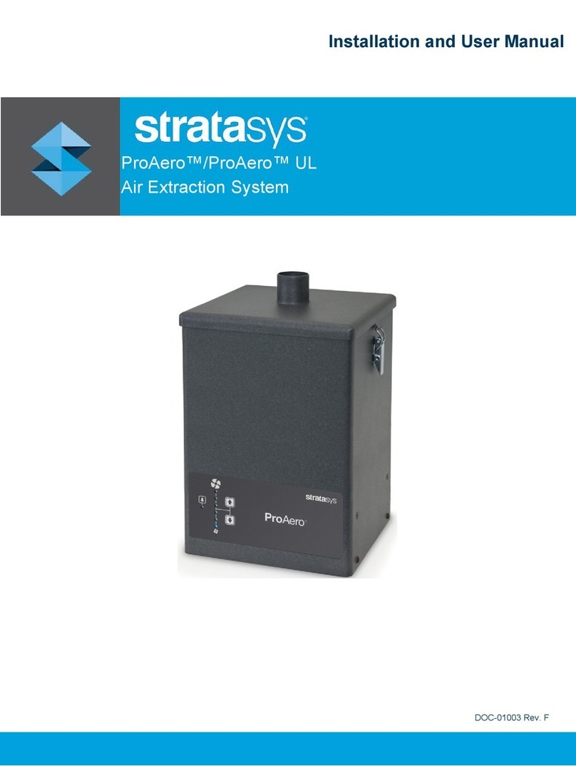
Stratasys ProAero+ User manual

DOC-01011 Rev. A
ProAero™+
Air Extraction System
Installation and User Manual

Copyright
Page ii
© Copyright 2021 Stratasys. All rights reserved.
Copyright Statement
© Copyright 2021 Stratasys. All rights reserved.
No part of this document may be photocopied, reproduced, or translated into any human or
computer language in any form, nor stored in a database or retrieval system, without prior
permission in writing from Stratasys. This document may be printed for internal use only. All
copies shall contain a full copy of this copyright notice.
Trademark Acknowledgments
Stratasys, Stratasys logo, J3 Series, J5 Series, ProAero, are trademarks of Stratasys Ltd.
and/or its subsidiaries or affiliates and may be registered in certain jurisdictions. All other
product names and trademarks are the property of their respective owners.
Confidentiality
This documentation contains Stratasys proprietary information. This information is supplied
solely to assist Stratasys authorized service engineers. No part of this document may be used
for other purposes, and it may not be disclosed to other parties. The specifications on which
this document is based are subject to change without notice.
Liability Statement
Stratasys shall not be liable for errors contained herein or for incidental or consequential
damages in connection with the furnishing, performance, or use of this material. Stratasys
makes no warranty of any kind with regard to this material, including, but not limited to, the
implied warranties of merchantability and fitness for a particular purpose. It is the responsibility
of the system owner/material buyer to determine that Stratasys material is safe, lawful, and
technically suitable for the intended application as well as identify the proper disposal (or
recycling) method consistent with local environmental regulations. Except as provided in
Stratasys' standard conditions of sale, Stratasys shall not be responsible for any loss resulting
from any use of its products described herein.
Disclaimer
Customer acknowledges the contents of this document and that Stratasys parts, materials, and
supplies are subject to its standard terms and conditions, available on
http://www.stratasys.com/legal/terms-and-conditions-of-sale, which are incorporated herein by
reference.
The specifications and/or information on which this document is based are subject to change
without notice.
Technical Service
If problems arise with this system please contact Stratasys Customer Support. Contact
information is available from the Stratasys website at:
http://www.stratasys.com/customer-support/contact-customer-support.
For comments on this guide: [email protected]
Manufactured by:
BOFA International
21-22 Balena Close
Poole, BH177DX, United Kingdom (UK)

Page iii
Contents
© Copyright 2021 Stratasys. All rights reserved.
Overview........................................................................................................ 1
Safety............................................................................................................. 2
Conventions used in this Guide ............................................................................................ 2
Electrical Safety .................................................................................................................... 2
Fire Safety............................................................................................................................. 3
Dangers to Eyes, Respiration, and Skin................................................................................ 3
Filter Selection ...................................................................................................................... 3
Warning and Information Labels ........................................................................................... 4
Preparation .................................................................................................... 4
Installation...................................................................................................... 5
Connecting to the Power Supply........................................................................................... 5
Connecting to the 3D Printer................................................................................................. 6
Connecting the Silencer (Optional) ....................................................................................... 7
Operation ....................................................................................................... 8
Setting the Desired Airflow .................................................................................................... 8
Maintenance .................................................................................................. 8
Inspecting the System ........................................................................................................... 9
Cleaning the System ............................................................................................................. 9
Replacing the Filters ............................................................................................................. 9
Disposing of the Filters........................................................................................................ 10
System Specifications.................................................................................. 11
Dimensions .......................................................................................................................... 11
Filter Information ................................................................................................................. 12

Page 1
© Copyright 2021 Stratasys. All rights reserved.
Overview
Figure 1: ProAero+ front
Figure 2: ProAero+ rear
Cover
Cover
clips (4)
Fan speed
adjustment
Power switch
100-240 VAC
power connector
Air inlet
Keep
covered
Control cable
connector
Control cable
switch

Conventions used in this Guide
Page 2
© Copyright 2021 Stratasys. All rights reserved.
Safety
Conventions used in this Guide
Below are safety-related symbols used on the extraction system and referred to within this
manual.
Electrical Safety
The air extraction system has been designed to meet the safety requirements of the Essential
Health and Safety Requirements of the Machinery Directive 2006/42/EC.
Disconnect the power from the system before opening the cover.
To reduce the risk of fire, electric shock, or injury:
1. Always disconnect the system from the main power supply before servicing.
2. Use this system only as described in this manual.
3. Connect the system to a properly grounded outlet.
Warning/Danger:
Refers dangerous situations which will result in death or severe injury. Refer to this
guide before proceeding when this symbol is displayed on the system.
Caution:
Refers to a possibly harmful situation. If not avoided, damage could be caused to the
system or its environment. Refer to this guide before proceeding when this symbol is
displayed on the system.
Important:
Refers to tips and other particularly useful information. This does not indicate a
dangerous or harmful situation.

Fire Safety
Page 3
© Copyright 2021 Stratasys. All rights reserved.
Fire Safety
This system is not designed to be used with processes that include any potential sources of
combustion.
It is the customer's responsibility to verify that any potential sources of combustion are
removed from the process before it reaches the system.
It is important that nozzles or other air extraction/fume capture devices and ductwork are
cleaned regularly to prevent the accumulation of potentially ignitable debris.
Dangers to Eyes, Respiration, and Skin
Dirty filters within the air extraction system contain a mixture of particulates, some of which
may be sub-micron size. Removing and replacing the filter agitates and releases some of these
particulates to the surroundings, enabling them to enter the respiratory system and eyes of the
operator. Additionally, depending on the materials used, the particulate might irritate the skin.
Filter Selection
The media within the filter in the air extraction system is capable of adsorbing a wide range of
organic compounds. However, it is the responsibility of the user to verify the media and filter
type are suitable for the particular application where the air extraction system is being used.
Caution:
Failure to clean the system and ductwork regularly may result in a fire in the system.
Warning: Hazardous Materials
When replacing filters always wear a mask, safety shoes, goggles, and gloves.
Caution:
This system must not be used with processes that use flammable materials, or with
explosive dusts and gases, without implementation of additional precautions.

Warning and Information Labels
Page 4
© Copyright 2021 Stratasys. All rights reserved.
Warning and Information Labels
The following labels appear on the air extraction system.
Preparation
Before installation, check the extraction system for damage. All packaging must be removed
before the system is connected to the power supply.
1. Move the system near the installation location and remove the outer packaging.
Labels Meaning Location
Goggles, gloves, and masks must be
worn when handling used filters. Front of system.
Electrical hazard. Removal of panels
with this label exposes electrical
components.
Back of system
Warning. Turn the power to the system
off before opening the panel with this
label.
Near the cover
release clips.
If the system is used in a manner that is not specified by the manufacturer, the system
warranty is void.
Important:
Read all instructions in this manual before using this system.
• Intended use: This device is intended for indoor use only, to extract and filter
fume from a variety of 3D printers.
• Install this system in a well-ventilated area.
• If you intend to vent the air from the system directly into the room, place the
system at least 50 cm (19.5 in.) from another object on the side of the air outlet
to ensure adequate airflow.
Caution:
Do not cover the exhaust outlets, as this restricts the airflow and causes overheating.

Connecting to the Power Supply
Page 5
© Copyright 2021 Stratasys. All rights reserved.
Installation
Connecting to the Power Supply
Follow the specifications listed in “System Specifications” (page 11) when selecting the power
supply outlet for the extraction system, and verify the power supply is suitable before
connecting the system.
The air extraction system features a fused IEC inlet for the power cable, as well as a main
power switch.
The power outlet at the site should be located near the system. The power cable should be
routed so as not to create a trip hazard.
Connect the power cable to the system. Only connect the cable to the power outlet after
finishing the installation process.
Warning: Electric Shock Hazard
The extraction system must be connected to a properly grounded outlet.
Important:
Check the integrity of the electrical power cable. If the power cable is damaged, do not
connect the extraction system to the main power supply with that power cable.
Have a suitable plug installed on the supplied power cable by a licensed electrician, or
purchase a similar cable locally with the proper plug.
A separate cable with a type B plug is supplied for the relevant countries.

Connecting to the 3D Printer
Page 6
© Copyright 2021 Stratasys. All rights reserved.
Connecting to the 3D Printer
Several types of adapters are supplied with the system. You connect only the relevant adapters
for your printer type.
Adapter Used For
Insert this onto one end of the flexible duct, and connect the adapter to the
back of the ProAero+.
Note: Secure the metal bands after connecting. Do not remove the 2 smaller
caps on the back of the ProAero+.
For all 350/500 Eden, Connex, and Objet printers: insert the additional
adapter onto the other end of the duct and connect it to the printer exhaust
outlet
Note: Secure the metal bands after connecting. Do not remove the 2 smaller
caps on the back of the ProAero+.
For all J7 series printers and J835/J850 printers: insert this onto the other end
of the duct and connect it to the printer exhaust outlet.
Note: Secure the metal bands after connecting. Do not remove the 2 smaller
caps on the back of the ProAero+.
For all Objet260 and J826 printers: screw this on to the other end of the duct
(counterclockwise) and connect it to the printer exhaust outlet.
A control cable is supplied with the system. This is for future use. Save this for when
this option is available.

Connecting the Silencer (Optional)
Page 7
© Copyright 2021 Stratasys. All rights reserved.
Connecting the Silencer (Optional)
The ProAero+ is supplied with a silencer to reduce the noise of the exhaust from the system.
Installing the silencer is optional, and you can do this at a later time if needed.
To connect the silencer:
1. Place the system slightly forward of its final location, and position the rear wheels of the
system so they are facing towards the front of the system.
2. Place the silencer on the floor behind the system, with the lower part of the silencer facing
the system.
Figure 3: Silencer positioned behind system
3. Either push the silencer forward so it moves under the system, or roll the system straight
back until it covers the lower part of the silencer completely, and is touching the higher part
of the silencer.
4. Lock the front wheels of the system.
It is difficult to move the system after connecting the silencer, so move the system
as close to the desired location as possible before continuing.
The rear wheels of the system need to be facing forward to allow the silencer to fit
underneath the system.
Lower part
of silencer

Setting the Desired Airflow
Page 8
© Copyright 2021 Stratasys. All rights reserved.
Operation
Setting the Desired Airflow
The air extraction system features a manual flow control that enables the user to adjust the
required airflow rate. Over time, as the filters become restricted, the user should manually
increase the motor speed to maintain the correct flow rate, and compensate for any loss in
performance.
To adjust the airflow:
1. Turn on the power switch.
2. Press and hold for 2 seconds to increase airflow and press and hold for 2
seconds to decrease airflow. The level of airflow is indicated on the vertical row of six blue
LEDs. As you increase the airflow, more blue LEDs light.
Figure 4: Control panel
Maintenance
User maintenance is limited to cleaning the system and filter replacement. Only Stratasys
technicians are authorized to perform component testing and replacement.
The system and all connecting tubes must be fully installed and connected before the
airflow is set.
When first installing the system, set the airflow on the third LED from the bottom.
The filter change indicator is red initially after turning on the system, and then turns
green after a short while.
Filter change
indicator
Fan speed
adjustment
Warning: Personal Injury Hazard
Unauthorized work or the use of unauthorized replacement filters may result in a
potentially dangerous situation and/or damage to the extraction system, and will void
the manufacturer’s warranty.

Inspecting the System
Page 9
© Copyright 2021 Stratasys. All rights reserved.
Inspecting the System
If required by local laws and regulations, this system must be inspected.
Contact Stratasys for more information about inspection and certification.
Cleaning the System
• Clean the exterior of the system with a damp cloth and non-aggressive detergent.
• Clean the cooling inlets and outlets once a year to prevent accumulation of dust, and
thereby overheating of the system.
Replacing the Filters
To maintain performance, it is important that you replace the filters with identical replacement
filters. To re-order, refer to the filter number printed on the filter installed in your extraction
system.
Caution:
Do not use an abrasive cleaning product as this will damage the finish.
The ProAero+ contains a single combined filter.
Caution:
To prevent overheating, do not use the system with a blocked filter, or with dust
obstruction of inlets/outlets.
It is recommended to have spare filter(s) on site to avoid prolonged system
unavailability. Part numbers for replacement filters can be found on the filter(s) fitted
in your system.

Disposing of the Filters
Page 10
© Copyright 2021 Stratasys. All rights reserved.
Replace the filters when the maintenance LED, shown in Figure 5, turns from green to red and
flashes, or when the system no longer removes fumes efficiently.
The printer software notifies you when to replace the combined filter.
The recommended replacement schedule is as follows:
• Combined filter: every 350 printing hours or 6 months, or sooner if the filter replacement
indicator turns red and flashes.
Figure 5: Filter replacement indicator on control panel
To replace the combined filter:
1. Turn off the system power switch.
2. Open the clips on the sides of the system and remove the cover.
3. Lift the filter out of the system.
4. Insert the new filter into position.
5. Replace the cover, and fasten the clips.
Disposing of the Filters
The combined filter is manufactured from non-toxic materials. Filters are not re-usable. The
method of disposal of the used filters depends on the material deposited on them.
It is the customer's responsibility to verify that the disposal of filters complies with all local
and/or industrial regulations.
If the fan speed is higher than recommended, the filter will become clogged earlier
than expected. The fan speed level should not be set below level 2.
It is recommend to place the used filters in a sealed bag before discarding.
Do not activate the system without a filter.

Dimensions
Page 11
© Copyright 2021 Stratasys. All rights reserved.
System Specifications
• Capacity: 380 m³/h (223 CFM)
• Fan type: Centrifugal
• Power: 1100 W
• Voltage: 100-230 VAC
• Frequency: 50/60 Hz
• Full Load Current: 12.5 A
• Noise Level: Below 65 dBA (at typical operating speed)
• Overvoltage category: II
• Maximum altitude: 2000 m (6561 ft.)
• Allowable voltage input fluctuation: +/-10%
• Control cable: 22-48 VDC input, 20 mA
• Operating temperature range: +5 °C to + 40 °C (41 °F to 104 °F)
• Operating humidity range:
• Max 80% Relative Humidity up to 31 °C (88 °F)
• Max 50% Relative Humidity at 40 °C (104 °F)
• Pollution degree: 2
• Intended use: Indoor
Dimensions
Metric (mm) Imperial (inches)
Crate: (Weight: 72 kg / 159 lbs)
Height 1180 46.5
Width 670 26.4
Depth 500 19.7
Unpackaged: (Weight: 51 kg / 113 lbs)
Height 625 24.6
Width 525 20.67
Depth 385 15.16

Filter Information
Page 12
© Copyright 2021 Stratasys. All rights reserved.
Filter Information
Filter Type Construction Efficiency
Combined
Filter
HEPA
Maxipleat Construction
with Webbing Spacers 99.997% @ 0.3 microns
Carbon Granules NA

THE 3D PRINTING SOLUTIONS COMPANY
www.stratasys.com
_____
Copyright © 2021 Stratasys Ltd. All rights reserved.
DOC-01011 Rev. A
Table of contents
Other Stratasys Scrubber manuals