Electrolux WHB5 500H User manual

Installation manual
Washer-extractors
WHB5 500H
Clean room
original instructions 05201135CR/EN


Contents
Contents
1 . Safety precautions.............................................................................................................................5
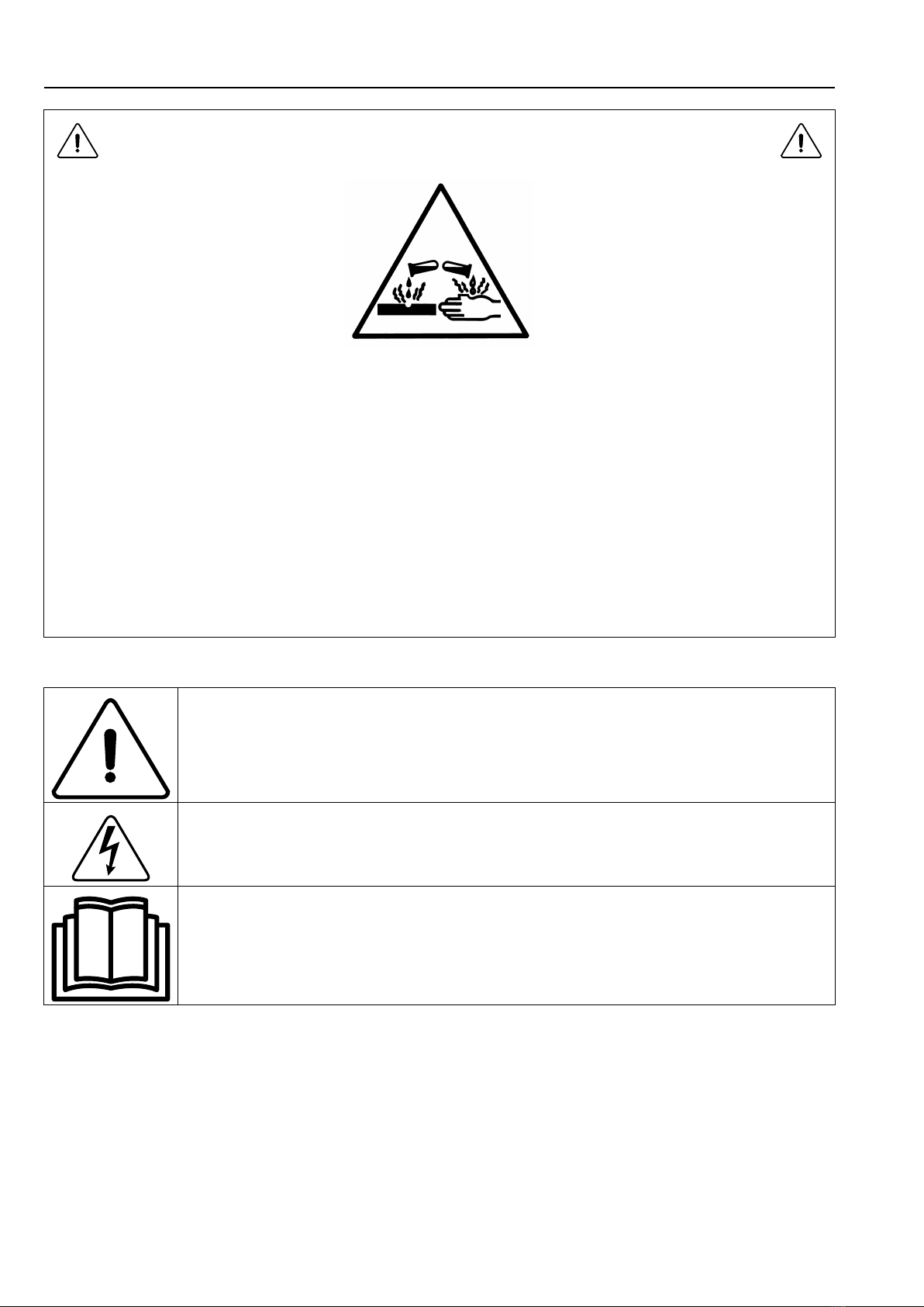
1.1 Symbols..................................................................................................................................10
1.2 Personal protection equipment..................................................................................................10
1.3 Preliminary instructions ............................................................................................................ 11
2 Environmental information .................................................................................................................12
3 Locking and tagging procedure...........................................................................................................12
4 Handling...........................................................................................................................................14
4.1 Lifting with a fork-lift truck .........................................................................................................14
4.2 Lifting with handlings straps......................................................................................................14
5 Packing-Weight.................................................................................................................................15
5.1 Packing...................................................................................................................................15
5.2 Weight ....................................................................................................................................16
6 Technical characteristics ....................................................................................................................16
6.1 Technical data .........................................................................................................................16
6.2 Connections ............................................................................................................................17
6.3 Dimensions — WHB5500H.......................................................................................................20
6.4 Dimensions — WH5500H.........................................................................................................22
7 Sound levels .....................................................................................................................................23
8 Working place lighting........................................................................................................................23
9 Supplies ...........................................................................................................................................24
10 Barrier partition .................................................................................................................................24
11 Mechanical installation.......................................................................................................................25
11.1 Unpacking...............................................................................................................................25
11.2 Installation...............................................................................................................................25
11.3 Installing the shock absorber runners ........................................................................................26
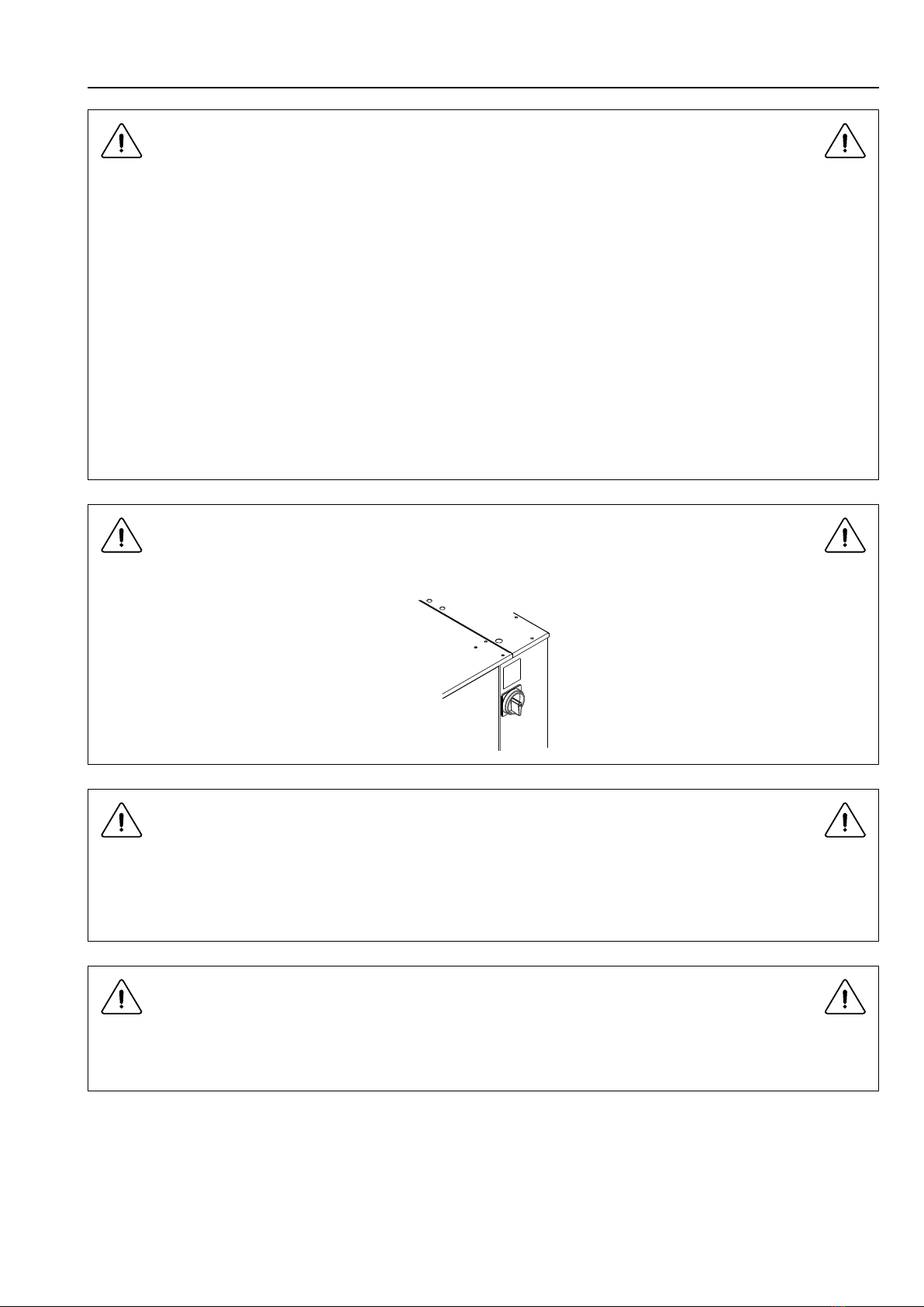
11.4 Instructions for securing the machine on the ground ...................................................................26
12 Remove of the transport locks fitted ....................................................................................................28
13 Drain connection ...............................................................................................................................29
14 Waters connections ...........................................................................................................................30
15 Liquid detergents connection..............................................................................................................31
15.1 Connection scheme of liquid detergents ....................................................................................32
15.2 Electrical liquid detergents' connection ......................................................................................33
16 Steam connection .............................................................................................................................34
17 Air vent connection............................................................................................................................35
18 Note about the A.C. power .................................................................................................................36
19 Feeder cable sections........................................................................................................................36
20 Electricity power supply .....................................................................................................................38
21 Compressed air connection................................................................................................................40
22 Function checks ................................................................................................................................41
23 Conversion of measurement units.......................................................................................................43
The manufacturer reserves the right to make changes to design and component specifications.


Installation manual 5
1 . Safety precautions
CAUTION
Before any use, to retire all the parts needed to install the machine put
in the drum , please follow these actions
1. connect compressed air.
2. Remove the side housing cabinet.
3. Press with a screwdriver on D3B (see picture below).
4. Open the loading door.
5. Open the drum doors , with precautions, maintain the 2 doors.
6. Get the package and instructions.

6Installation manual
CAUTION
Before any use, it is compulsory to read the instruction handbook.
Users must have learnt how the machine operates.
The machine is only intended for water-wash use.
Do not allow minors to use the machine.
Do not hose down the machine with water.
Only use detergent intended for water-wash of textiles Never use dry
cleaning agents.
It is forbidden to wash textiles soaked with solvents.
The machine's door lock must under no circumstances be bypassed.
If the machine develops a fault, this must be reported to the person in
charge as soon as possible. This is important both for your safety and
that of others.
DO NOT MODIFY THIS APPLIANCE.
Servicing shall be carried out only by authorized personnel.
Only authorized spare parts shall be used.
When performing service or replacing parts, the power must be
disconnected.
When the power is disconnected, the operator must see that the ma-
chine is disconnected (that the plug is removed and remains removed)
from any point to which he has access. If this is not possible, due to
the construction or installation of the machine, a disconnection with a
locking system in the isolated position shall be provided.
In accordance with the wiring rules : mount a multi-pole switch prior to
the machine to facilitate installation and service operations.
In order to prevent damage to the electronics (and other parts) that
may occur as the result of condensation, the machine should be
placed in room temperature for 24 hours before being used for the first
time.
In case of a gas heated machine, do not assemble the machine on
premises containing a dry cleaning machines or other similar
machines.
Please wash only items offering appropriate distribution inside the
drum. Do not wash items such as mattresses or shoes. Call our techni-
cal departments before washing nonstandard items. Noncompliance
with these instructions may void the manufacturer's guarantee in case
of abuse of the washer-extractor.

Installation manual 7
CAUTION
For the following countries : AT, BE, BG, HR, CY, CZ, DK, EE, FI, FR,
DE, GR, HU, IS, IE, IT, LV, LT, LU, MT, NL, NO, PL, PO, PT, RO, SK,
SI, ES, SE, CH, TR, UK : This appliance shall not be installed where
the public has access.
For other countries : This appliance is not intended for use by persons
(including children) with reduced physical, sensory or mental capabil-
ities, or lack of experience and knowledge, unless they have been giv-
en supervision or instruction concerning use of the appliance by a
person responsible for their safety and understand the hazards in-
volved. Children should be supervised to ensure that they do not play
with the appliance.
IMPORTANT
The identification plate is located on the right side.
IMPORTANT
Make sure note to over load the machine. Maximum mass of dry cloth
is found in Technical data.
Sound pressure level is found in Technical data.
IMPORTANT
Never try to open the outer drum door before the complete stop of the
cage.

8Installation manual
CAUTION
Disconnect all the sources of energy before any intervention on the
machine.
The machines comply with the European Directive EMC (Electromag-
netic Compatibility). They have been tested in laboratory and ap-
proved as such. It is so prohibited to add wires or nonshielded electric
cables in the cabinets, strands or cables' troughs.
Considering that the volume of the outer drum is superior to 150 litres,
the standard kept for the electric part is the IN 60204.
CAUTION
With AIDO(Automatic Inner Door Opening) option, Take care of the
disc of the opening system above your head. Risk of cutting with the
edge of the disc!!
Take care also of the locking system on your side; risk of cutting with
the edge of the plate!!
CAUTION
When you put your hands into the drum, take care of the edge of the
outer drum doors on yours sides. Risk of cutting with the edge of the
metal plate!!
CAUTION
The machine can work without the protective casing when the electric
supply is not cut off.
Interlock the main isolating switch with a padlock.
Close the steam or gas inlet valves.

Installation manual 9
IMPORTANT
Ensure that the machine is not loaded beyond its nominal capacity
(see "Specific load" in the instruction booklet’s technical
characteristics).
An excessive load has consequences for the lifetime of the machine’s
organs, as follows:
• Rapid destruction of the suspension elements (springs, shock
absorbers);
• Excessive fatigue of motorization elements (engine, belt);
• Rapid reduction of lifetime of drum bearings (rolling bearings);
• Opening and destruction of drum doors and tank doors during oil
dehydration.
This is particularly important for your safety and that of others.
The consequence is an immediate cancellation of the warranty.
THINK OF THE ENVIRONMENT!
The use and handling of chemical products such as detergent, chlor-
ine, acids, descaling agents, etc may create hazards for health and en-
vironment ; the following precautions should be taken:
• Do not breathe the dusts or steam;
• Avoid contact with skin or eyes (may cause burns);
• In case of important spillage, wear a protecting mask, gloves, and
eye protectors;
• Handle with care;
• Consult the use and first aid advice on the packing;
• Do not dispose pure products in the environment.

10 Installation manual
WARNING
The use and handling of chemical products such as detergent, chlor-
ine, acids, antiliming agents etc... may create hazards for health and
environment ; the following precautions should be taken.
- Do not breathe the dusts or steam.
- Avoid contact with skin or eyes (may cause burns).
- In case of important spillage, wear a protecting mask, gloves, and
eye protectors.
- Handle with care.
- Consult the use and first aid advice on the packings.
- Do not dispose pure products in the environment.
1.1 Symbols
Caution.
Caution, presence of dangerous current.
Read the instructions before using the machine.
1.2 Personal protection equipment
Given below is a summary table of the Personal Protection Equipment
(PPE) to be used during the various phases of the machine’s service life.

Installation manual 11
Phase Protection
garments
Safety
footwear
Gloves Glasses Ear protectors Mask Safety helmet
Transport XO
Handling XO
Unpacking XO
Installation X O
Normal use X X X X
Adjustments OX
Routine
cleaning OX X O
Extraordinary
cleaning OX X O
Maintenance OXO
Dismantling OXO
Scrapping OXO
Legend :X: PPE required ; O: PPE available or to be used if necessary.
Normal use : Safety footwear must be defined for a use on a wet floor.
And use glasses and gloves to manipulate chemical products.
1.3 Preliminary instructions
WARNING
Risk of jamming when opening the lower door for unloading
WARNING
Risk of jamming with trolley and lower door when opening (if trolley
height = 900mm)

12 Installation manual
WARNING
Risk of the upper door being raised quickly on loading
2 Environmental information
Concerned by providing the end user with useful and necessary environmental information, we wish to precise:
• Data about energetic consumptions, wastes (atmospheric and liquid) and sound level are indicated in the para-
graph «Technical characteristics».
• Foreseeing its recycling, this machine is fully dismantable.
• This machine is free from any asbestos.
• In conformity with French regulations:
– Law No. 76-663 of July 19th 1976;
– Decree No. 77-1133 of September 21st 1977;
– The decree of 7th July 1992;
– The decree of 29th December 1993;
– The decree of 28th December 1999;
– No. 2311 of the nomenclature for classified installations.
Commercial linen cleaning laundries and launderettes are subject to:
– prefectural authorisation if the washing capacity exceeds five tonnes per day,
– a declaration to the prefecture if the washing capacity exceeds 500 kilos per day but is below or equal to five
tonnes per day.
• In application of the Law of 15 July 1975 and the decrees of 01 April and 13 July 1994 on the disposal of industrial
and commercial packing waste «All owners of packing waste producing a weekly volume below 1100 litres can for-
ward these to the local collection and treatment department. If exceeding this volume, the owners of packing
waste will ensure their valuation by reuse, recycling or, any other action aiming at producing reusable materials or
energy... or provide them contractually to a certified intermediate authorised to transport, trade or broke waste».
Therefore, these texts forbid:
– land filling raw waste;
– open air burning or incineration without energy collection.
• Packaging of our machines are according with the provisions of decree 98-638 from July 20 1998 related to envi-
ronment requirements.
For additional information, do not hesitate to consult with our environmental department.
3 Locking and tagging procedure
A red insert at the beginning of this instruction handbook schematically shows the locking and tagging procedure de-
scribed below. If you wish, you can detach this insert and display it close to the machine to remind maintenance per-
sonnel of the safety instructions.

Installation manual 13
Always respect items 2, 3 and 4 carefully before doing any repair or maintenance work on
the machine.
Put the main switch to Off
and lock the handle with a
padlock in one of the
three holes provided for
this purpose.
Close the stop valves for
the other supplies (steam,
gas, thermal fluid, com-
pressed air) to stop and
lock their handle with a
padlock.
Open the fixed protectors
(casings, doors) with the
key provided or a special
tool.
Do the maintenance.
Close and carefully lock the fixed protectors.
Unlock the stop valves and the main switch.

14 Installation manual
4 Handling
Important
It is obligatory that all these operations are undertaken by handling specialists.
Before any handling, check that the four transport locks fitted are still in place and well-tightened.
To do so, remove the front and rear casings and check presence of four locks (B).
4.1 Lifting with a fork-lift truck
Warning
You should never handle the machine in its longitudinal side (any other than shown on the drawing below) with a
fork-lift truck. Important risk of parts deterioration for those fixed under the machine.
This can be carried out from the front or back, at the centre of the machine.
4.2 Lifting with handlings straps
Lifting in that case can only be done with handling straps (minimum capacity 1000 daN / 2200 lb) which bear weight
of the machine.
Remove the top cover and pass the straps in the lifting holes.

Installation manual 15
Caution
Make sure to place the straps correctly to avoid any bending of parts of the machine.
Caution
In order to avoid any bending of casings, you should never climb and stand on top of the machine.
5 Packing-Weight
5.1 Packing
Packing dimensions in mm/in Size A Size B Size C
Washer extractor type WH5500H 1570 / 61.81 1520 / 59.85 1980 / 77.95
Washer extractor type WHB5500H 1570 / 61.81 1520 / 59.85 1980 / 77.95

16 Installation manual
5.2 Weight
Weight in kg/lb (machine + crate)*
Washer extractor type WH5500H x
Washer extractor type WHB5500H 1280 / 2822
* Precise weight depends on accessories fitted.
6 Technical characteristics
6.1 Technical data
Units WH5500H WHB5500H
Drum diameter mm 920 920
Drum length mm 800 800
Drum volume litre 500 500
Opening inner drum doors (LxH) mm 670x470 670x470
Opening outer drum door (LxH) mm 645x738 645x738
G-factor, max. 350 350
Specific load 1/10 kg 50 50
Floor area m² 1.63 1.63
Max. unbalance kg 6.5 6.5
Net weight kg x* 1170*
Weight loaded (high level) daN 300 300
Water volume, washing (low level) l 125 125
Water volume, washing (high level) l 250 250
Heat loss 3 % of installed heating power
* Precise weight depends on accessories fitted.

Installation manual 17
6.2 Connections
Water Units WH5500H WHB5500H
Water valves connection mm-BSP DN20–3/4″ DN20–3/4″
Capacity at 250 kPa l/min 70 70
Functioning limits for water valve kPa 50–300 50–300
Water consumption for a wash program1l 542 542
Drain Units WH5500H WHB5500H
Drain connection, outer ⌀mm 75 75
Maximum drain flow rate l/min 240 240
Waste water collector DN-mm 150 150
Air vent Units WH5500H WHB5500H
Air vent connection, outer ⌀mm 60 60
Steam Units WH5500H WHB5500H
Steam inlet, standard mm-BSP DN20–3/4″ DN20–3/4″
Steam inlet, low pressure mm-BSP DN25–1″ DN25–1″
Recommended steam pressure kPa 300–600 300–600
Recommended steam pressure (low pressure heating) kPa less than 50 less than 50
Functioning limits for steam valve kPa 100–600 100–600
Steam instantaneous flow rate at 600 kPa kg/h 24.5 24.5
Steam consumption for a normal cycle¹ ISO 93 98–4 standard
type C kg at 600 kPa 24.5 24.5
Steam consumption for a normal cycle¹ ISO 93 98–4 standard
type C kg at 50 kPa 21.4 21.4
Indirect steam Units WH5500H WHB5500H
Thermic fluid inlet or indirect steam heating mm-BSP DN15–1/2″ DN15–1/2″
Thermic fluid return or indirect steam heating mm-BSP DN15–1/2″ DN15–1/2″
Maximum supply pressure kPa 600 600
Installed calorific power kW 131 131
Average calorific consumption kWh 6.3 6.3
Inner volume thermic fluid l 2.4 2.4
Electricity Units WH5500H WHB5500H
Supply voltage V 380/415 380/415
Frequency Hz 50/60 50/60
Electric cable (section) mm² See chapter “Feeder cable section”
Rated electric power, gas heating kW 8.7 8.7
1. ISO 93 98–4 standard type C.

18 Installation manual
Rated electric power, electric heating kW 38.5 38.5
Rated electric power, steam heating / indirect steam heating kW 8.4 8.4

Installation manual 19
Heating Units WH5500H WHB5500H
Installed heating power, gas heating kW 40 40
Installed heating power, electric heating kW 36 36
Electric consumption for a standardized cycle, electric heating kWh 10.7 10.7
Electric consumption for a standardized cycle, steam heating kWh 1.2 1.2
Floor load Units WH5500H WHB5500H
Frequency of the dynamic force Hz 13.75 13.75
Max transmitted floor load daN 1808+-75 1808 +-75
Max. pressure transmitted to floor kPa 11.77 11.77
Compressed air Units WH5500H WHB5500H
Compressed air inlet mm 6/8 6/8
Min./max. compress air pressure bar 4.5/6 4.5/6
Consumption l/h 50 10

20 Installation manual
6.3 Dimensions — WHB5500H
WHB5500H
A B C D E F G H I J K L M
1300 1265 1770 920 40 40 1385 450 220 195 80
N O P QR S T U V W X Y Z
160 840 670 635 650 1560 85 270 860 2330
Front view Left view
1Control panel 10
2Loading door 11 Air vent connection
3Unloading door 12 Electrical connection
4 13 Compressed air inlet
5Cold hard water inlet 14 Main switch
6 15 Electric cable
7 16
8Steam connection 17 Rubber plate
9Drain connection 18 Waste water collector
Table of contents
Other Electrolux Scrubber manuals

Electrolux
Electrolux AW 445 User manual

Electrolux
Electrolux EFC 9650 User manual

Electrolux
Electrolux Washer User manual

Electrolux
Electrolux W465H User manual

Electrolux
Electrolux WH6-6 User manual

Electrolux
Electrolux W.55.H User manual

Electrolux
Electrolux WE170V User manual

Electrolux
Electrolux Flymo Hover Vac Operating manual
Popular Scrubber manuals by other brands

BEST SANITIZERS
BEST SANITIZERS BSX Boot Scrubber Series user manual

Minuteman
Minuteman MC17026-00 Operating and service guide

American-Lincoln
American-Lincoln SC7740 Operator's manual & parts list

HAKO
HAKO Scrubmaster B 120 R Operation

Parish Supply
Parish Supply 1000DX-200 Speedster instruction manual

Nilfisk-Advance
Nilfisk-Advance CS7000 Fuel Cell EcoFlex How-to guide