Strategic Vista SG250 User manual
Before operating the system, please read this manual thoroughly and
retain it for future reference!!!
5” 4-CHANNEL B&W
OBSERVATION SYSTEM
MODEL SG250,
SG251 & SG254
FOR MORE INFORMATION
WWW.STRATEGICVISTA.COM
Rev 03/03 - 1

CAUTION
RISK OF ELECTRIC SHOCK. DO NOT OPEN.
CAUTION: TO REDUCE THE RISK OF ELECTRIC SHOCK, DO NOT
REMOVE COVER (OR BACK). NO USER-SERVICEABLE PARTS
INSIDE. REFER SERVICING TO QUALIFIED SERVICE
PERSONNEL.
!
Explanation of two Symbols
The lightning flash with arrowhead symbol, within an equilateral triangle, is intended to alert
the user to the presence of uninsulated "dangerous voltage" within the product's enclosure that
may be of sufficient magnitude to constitute a risk of electric shock to persons.
The exclamation point within an equilateral triangle is intended to alert the user to the presence
of important operating and maintenance-(servicing) instructions in the literature accompanying
the appliance.
THE GRAPHIC SYMBOLS WITH SUPPLEMENTAL MARKING ARE ON THE BOTTOM OF THE SYSTEM.
!
WARNING: To prevent fire or shock hazard, do not expose this appliance to rain, water, or
wet locations. Do not insert any metallic object through the ventilation grills.
IMPORTANT SAFETY INSTRUCTIONS
This wireless A/V equipment is provided with a polarized alternating-current line plug (a plug having one
blade wider than the other). This plug will fit into the power outlet only one way. This is a safety feature. If
you are unable to insert the plug fully into the outlet, try reversing the plug. If the plug still fail to fit, contact
your electrician to replace your obsolete outlet. Do not defeat the safety purpose of the polarized plug.
FCC CLASS B NOTICE
Note:
This equipment has been tested and found to comply with the limits For a Class B digital device, pursuant to Part 15
of the FCC Rules. These limits are designed to provide reasonable protection against harmful interference in a
residential installation. This equipment generates, Uses and can radiate radio frequency energy and, if not installed
and used in accordance with the instruction, may cause harmful interference to radio communications. However,
there is no guarantee that interference will not occur in a particular installation. If this equipment does cause harmful
interference to radio or television reception, (which can be determined by turning the equipment off and on), the user
is encouraged to try to correct the interference by one or more of the following measures:
• Reorient or relocate the receiving antenna.
• Increase the separation between the equipment and receiver.
• Connect the equipment into an outlet on a circuit different from that to which the receiver is connected.
• Consult the dealer or an experienced radio or television technician for help.
1

SAFETY INSTRUCTIONS
IMPORTANT SAFEGUARDS
All the safety and operating instructions should be read before the appliance is operated
and retained for future reference.
1. HEED WARNINGS - All warnings on the appliance and in the operating instructions should be
adhered to.
2. FOLLOW INSTRUCTIONS - All operating instructions should be followed.
3. WATER AND MOISTURE - Do not use this video product near water – for example, a bath tub, wash
bowl, kitchen sink, laundry tub or swimming pool, or in a wet basement.
4. POWER SOURCES - This product should be operated only from the type of power source indicated on
the marking label.
5. OVERLOADING - Do not overload outlets and extension cords, which can result in a risk of fire or
electric shock.
6. SERVICING - Do not attempt to service this product yourself. Opening or removing covers may
expose you to dangerous voltage or other hazards. Refer all servicing or repairs to qualified service
personnel.
7. DAMAGE REQUIRING SERVICE - Unplug this product from the wall outlet and refer servicing or
repairs to qualified service personnel under the following conditions:
a. When the power supply cord or plug is damaged.
b. If liquid has been spilled or objects have fallen into the product.
c. If the product has been exposed to rain or water.
d. If the product does not operate normally by following the operating instructions. Adjust only those
controls that are covered by the operating instructions.
e. If the product has been dropped or the cabinet has been damaged.
f. When the product exhibits a distinct change in performance.
8. REPLACEMENT PARTS - When replacement parts are required, be sure the service technician has
used replacement parts that are specified by the manufacturer or have the same characteristics as the
original part. Unauthorized substitutions may result in fire, electric shock, or other hazards.
9. SAFETY CHECK - Upon completion of any service or repairs to this video product, ask the service
technician to perform safety checks to determine if the video product is in proper operating condition.
10. An appliance and cart combination should be moved with care.
Do not place this equipment on an unstable cart, stand, or table. The equipment may fall, causing
serious injury to a child or adult, and serious damage to the equipment. Wall or shelf mounting should
follow the manufacturer's instructions and should be done with a mounting kit approved by the
manufacturer.
2

Congratulations on your purchase of the Lorex 5” 4-Channel B&W Observation
System. This system has the capability of connecting up to four cameras,
allowing you to view up to four locations. The PIR Motion Sensor camera
included with some of the SG250 series models provides motion alarm sensing
function to alert the user of camera activity. Other features integrated with
this system include: two way audio, recording the picture to any VCR and
sequential or full screen viewing.
Lorex is committed to providing our customers with a high quality, reliable
product that customers have come to expect from us.
To learn more about this product and for a complete listing of Lorex
Video Security, Home Security and Remote Monitoring Systems, please visit us at:
www.strategicvista.com
CHAPTER TABLE OF CONTENTS PAGE
1. CONTROLS AND FUNCTIONS
MONITOR …..............................................………………………..….........….......4
CAMERA ...….……………......................................………………….……...……5
2. INSTALLATION
CAMERA .........................................................………………………....….............6
MONITOR ................................................................................................................6
3. SYSTEM OPERATION
CONNECTING MONITOR TO A VCR ……...………………….………......……7
4. TROUBLE SHOOTING ..............................................……………........….............7
5. OPTIONAL ACCESSORIES ....................................................................................8
5. SPECIFICATIONS ....................................................................................................9
6. SYSTEM INCLUDES ........…….........……….…….............................................…9
3
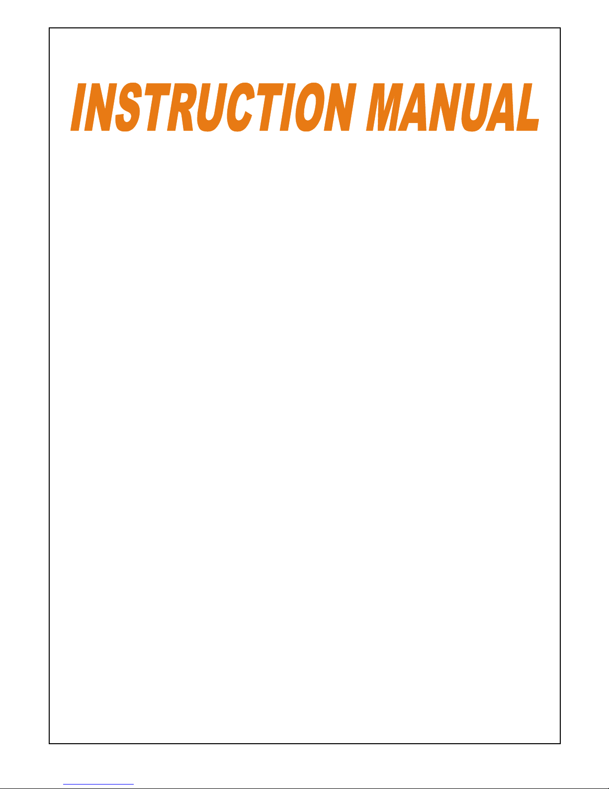
MONITOR CONTROLS – FRONT PANEL
1) On/Off Power Switch – Pressing this switch will turn the monitor ON/OFF. (Note: ensure this switch is set to the OFF position
prior to plugging into an electrical outlet).
2) Volume Control – Adjust this button to control the volume sound.
3) Brightness Control – Changes brightness of picture, turn left/right to adjust control.
4) Auto/Manual Button – Use this button to manually rotate between camera locations or automatically sequence between up to four
cameras.
a) Auto and Manual Viewing Options:
To manually view a specific camera location, press the Auto/Manual button. Press the Ch. Select key to view the
desired camera location. Auto Mode is used when more than 1 camera is connected to the Video Security system. The
system is preset to Manual Mode, with a default of 2 seconds. In Auto mode, the LED light will be ON.
Press the Auto/Manual button to return to the Auto Mode feature.
NOTE: In the event of a power failure, your system will automatically switch back to Channel 1. The user therefore
will manually adjust to reflect the previous channel that was set prior to the power failure.
b) Selectable Dwell Setting:
This system provides you the option of three selectable dwell options (2, 5 and 10 seconds) when set to Auto Mode.
This system is preset to two second selection.
Changing Dwell Mode
i) Press and hold the CH select button. The LED button will turn on to indicate that it is set to 2 seconds.
ii) Continue to press and hold the CH select button. The LED button will flash at a one second interval to indicate
that it is now set to the 5 second interval.
iii) Continue to press and hold the CH select button. The LED button will flash three times to indicate it is set to the
10 second interval.
5) Channel Button – Press this button to view desired channel.
6) Intercom Button – 2 Way Audio feature, allows the user to talk to a specific camera location. This button must be pressed the
entire time while talking.
7) Led Indicator Lights – Shows system status.
8) Speaker – picks up sound around the camera.
Your system is defaulted to Manual Mode on channel 1 (single location). To automatically scan between
the number of cameras connected, press the auto/manual button.
NOTE
4
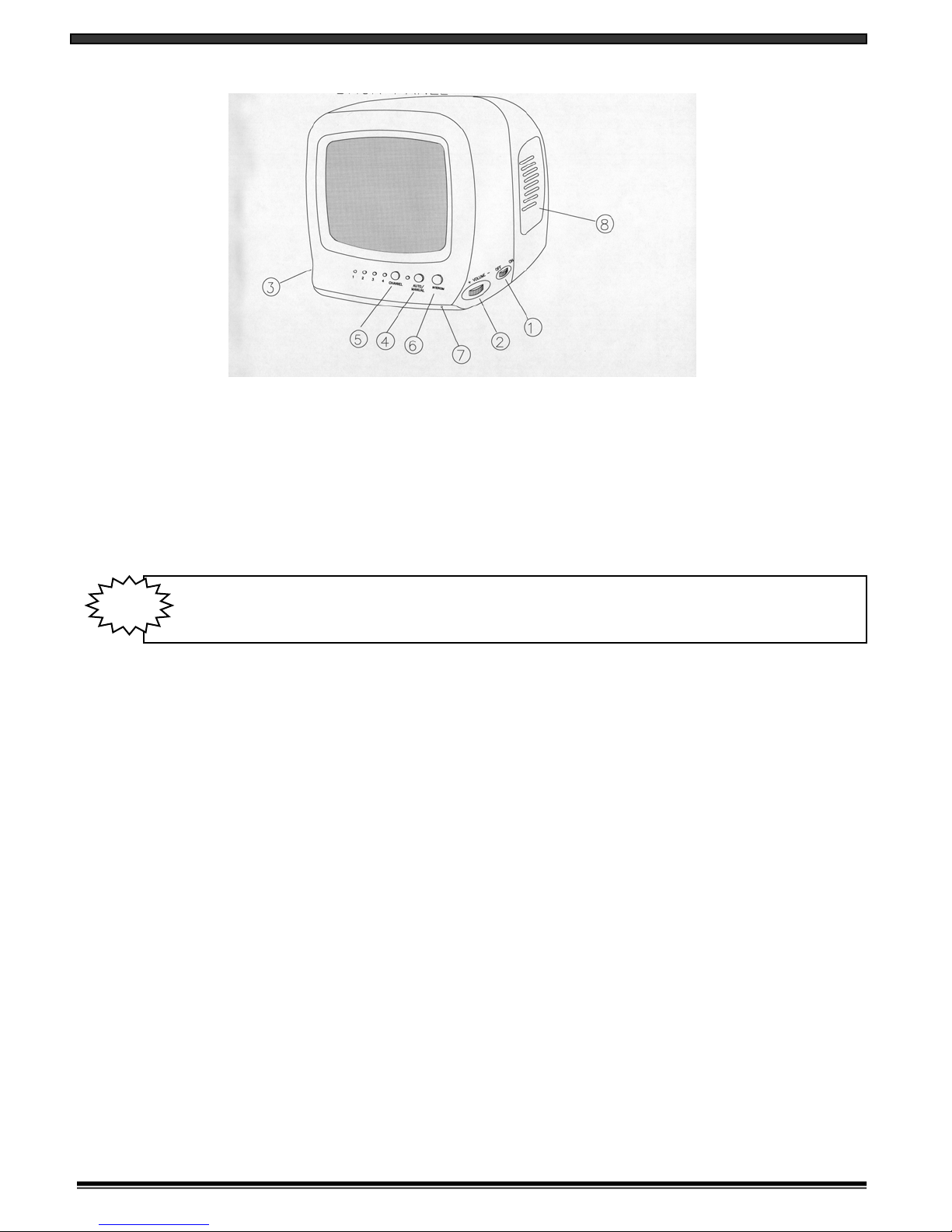
MONITOR CONTROLS – BACK PANEL
1) AC Input Jack – Power source to the monitor. Connect one end to the monitor; the other end to an electrical outlet.
2) VCR Audio Out – Use with A/V cables (not supplied) to connect to a recording device (eg. Time Lapse VCR).
3) VCR Video Out – Use with A/V cables (not supplied) to connect to a recording device (eg. Time Lapse VCR).
4) Contrast – Changes contrast of picture, turn left/right to adjust control.
5) Camera Inputs – Camera 1-4 inputs.
6) PIR Alarm Switch – Turns motion alarm detection On/Off.
WIRED CAMERA CONTROLS (wired camera sold separately)
1) Camera Lens – Displays wide angle camera viewing (6mm lens).
2) Microphone – Picks up sound around the camera.
3) Camera Input – Connects cable to monitor.
4) PIR Sensor – Used to detect motion at camera.
5) Speaker – Detects sound from the monitor to the camera.
6) Bracket – Metal bracket connects to camera for mounting on wall, ceiling or table.
5
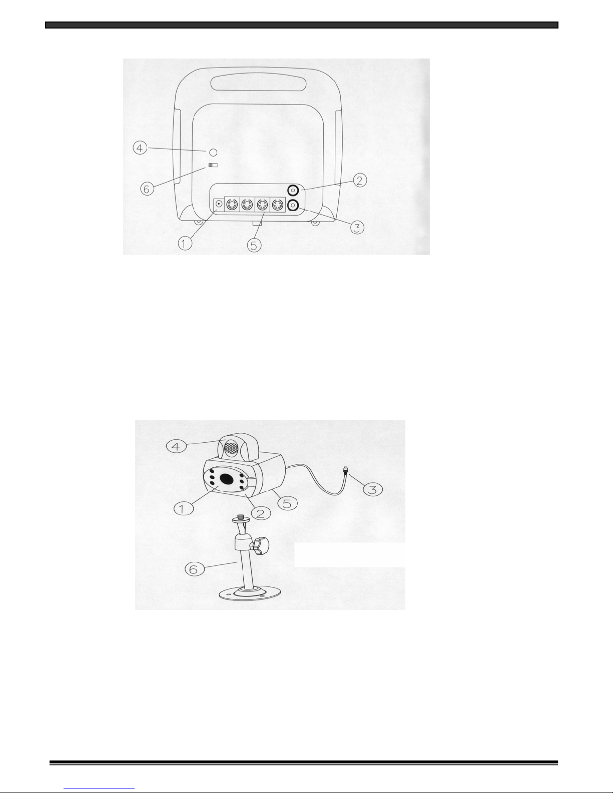
WIRED CAMERA INSTALLATION
1. Attach the stand base to the wall or ceiling where you want to install the camera. Locate a wall stud or ceiling joist and
secure bracket using the supplied mounting screws.
2. Attach the camera to the stand and firmly tighten the swivel.
3. Attach one end of the 65ft cable to the camera; the other end to the monitor.
IMPORTANT NOTE:
Keep camera installed away from direct sunlight. Also avoid places where humidity is high or
unable to protect rain. The mounting bracket must be attached to a structural device such as
a wall stud or ceiling after using suitable fastener.
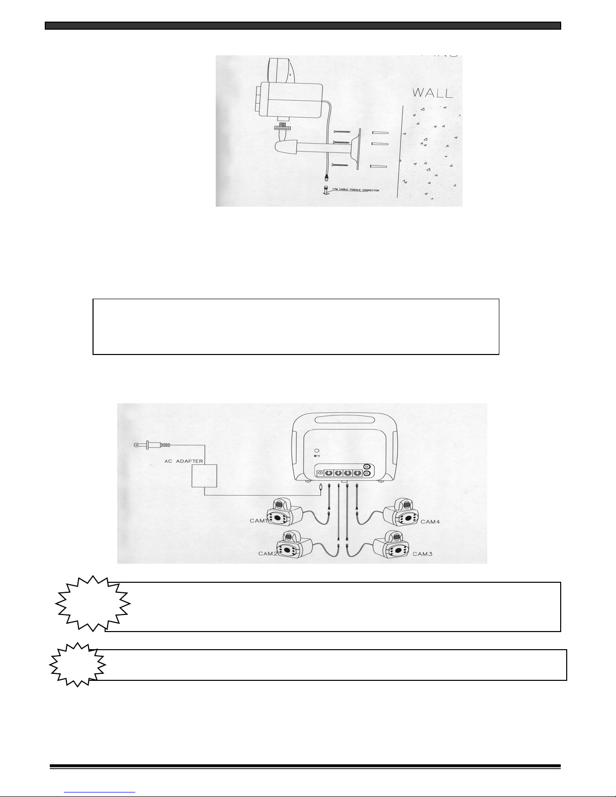
MONITOR CONNECTIONS
Depending on the system which you purchased, you may have 0–4
camera’s included with this system.
NOTE
Ensure the power switch on the monitor is set to the OFF position before proceeding with the following steps.
NOTE
1. Camera 1 Input
Connect one end of the supplied 65ft cable to the first wired camera, the other end to camera Input 1.
2. Camera 2 - 4 Inputs
Connect additional cameras to the camera 2 – 4 Inputs. (Not Included With Some Systems)
6

OPERATION
CONNECTING MONITOR TO A VCR
Monitor
RCA Cables
(not included)
Connections
Connect the supplied audio/video cable from the back of the monitor to the Audio/Video In of the VCR.
Did You Know?
You have the option of connecting this system to a Time Lapse VCR. A time lapse VCR provides you multiple
recording options allowing you to record up to 40 days using a standard T120 tape. Refer to the optional
accessories page for more details.
TROUBLE SHOOTING
If the system does not function properly, check the following points:
Make sure the camera is not facing any direct
light or sunlight
Picture flickering or Over Exposed
Check the cable for any lose connectionNo Picture
WIRED CAMERA
Check the condition of the POWER sourceShrinking picture
Adjust the VOLUMEPicture but no Sound
Clean the camera lens. Re-adjust the
CONTRAST or BRIGHTNESS controls
Poor picture quality
Check for AC connectionNO POWER
Re-adjust the CONTRAST or BRIGHTNESS
controls
Too dark or bright
MONITOR
REMEDYPROBLEM
FOR MORE INFORMATION
www.strategicvista.com
Because our product is subject to continuous improvement, SVC reserves the right to modify product designs and
specifications without notice and without incurring any obligation. E&OE
7
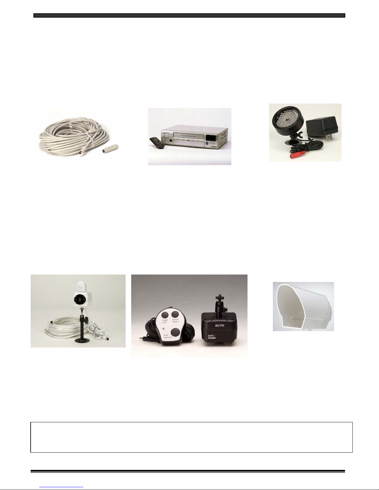
OPTIONAL ACCESSORIES
The following accessories are available to add to your existing system.
CABLE TIME LAPSE VCR NIGHTVISION
Weatherproof Night vision
accessory. Allows you to
see in the dark up to 35-40
distance (for use with
Observation system
cameras)
Used to record key events.
Select From a 40 hour real
time or 960 Hour time
lapse VCR
Extends viewing length
from Camera to monitor.
Available In 65, 100 and
250 ft lengths
OBSERVATION CAMERAS SUNSHADE HOUSINGAUTO PAN
Protects observation
camera from the sun
Accessory PIR motion
sensor observation
system camera with 2
way audio
Rotates camera up to 270°
TO ORDER THESE ACCESSORY ITEMS OR FOR A COMPLETE LINE OF ACCESSORIES
www.strategicvista.com
8

SPECIFICATIONS
WIRED WEATHER RESISTANT*CAMERA
B&W CMOS Camera
3.6mm
320 H X 240 V
2:1 interlace
Horizontal 400 TV Lines
0.1 Lux @ F2.0
1.0Vp-p/75 Ohm
0.45
Electrical Auto Iris
Shutter sensitivity :1/60-1/6,000
Electronic Condenser
-14º to + 122º F (-10ºC to + 50 ºC)
12V DC Power Supply
2” (W) x 2.5” (D) x 2.8” (H)
8 oz
Image sensor
Lens
Picture Elements
Scanning system
Resolution
Min. illuminations
Video Output
Gamma characteristics
Auto Iris
Microphone
Operating temperature
Power source
Dimensions
Weight
*Weather Resistant against Dust and Light Rain.
MONITOR
Screen Size 5” diagonal
Output level 1.0Vp-p/75ohm (Video),
1.0Vp-p (Audio)
Sensitivity -25dBm to -80dBm
Resolution More than 280 lines
Sound output 0.5 Watt.
Power Source 13.5V DC 1000mA
Dimension 6.5” (W) × 5.5”(H) × 7.5” (D)
Power consumption 800 mA
Operating Temperature 14º F to + 122º F (-10ºC to + 50 ºC)
Weight 3 Lbs.
SYSTEM INCLUDES
SG250 (INCLUDES) 5” B&W Monitor
AC Adapter
English, French and Spanish Owners Manual
SG251 (INCLUDES) 5” B&W Monitor
AC Adapter
1 – B&W Weather Resistant Camera
1 – 65 Ft. Cable
Mounting Brackets and Screws
English, French and Spanish Owners Manual
SG254 (INCLUDES) 5” B&W Monitor
AC Adapter
4 – B&W Weather Resistant Camera’s
4 – 65 Ft. Cable
Mounting Brackets and Screws
English, French and Spanish Owners Manual
9
This manual suits for next models
2
Table of contents


