manuals.online logo
Brands
  1. Home
  2. •
  3. Brands
  4. •
  5. Powerex
  6. •
  7. Air Compressor
  8. •
  9. Powerex 10 HP User manual

Powerex 10 HP User manual

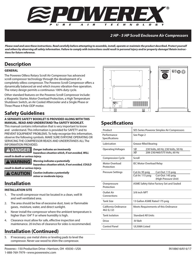
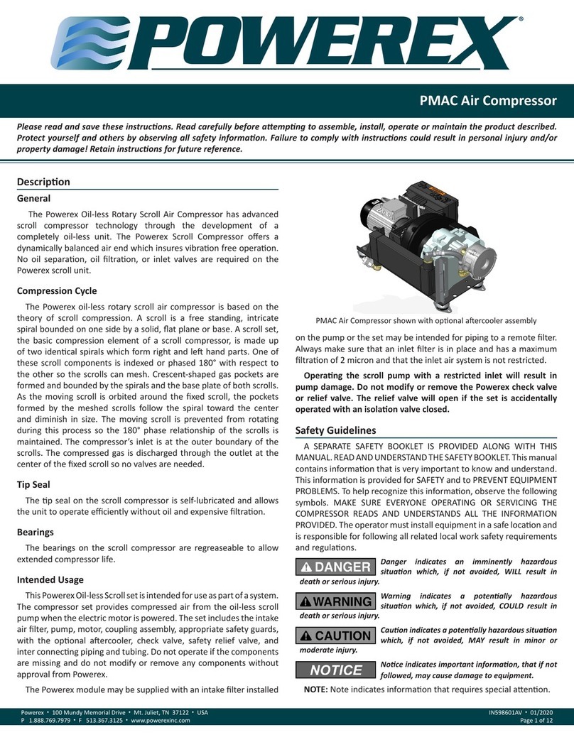
Please read and save these instructions. Read carefully before attempting to assemble, install, operate or maintain the product described.
Protect yourself and others by observing all safety information. Failure to comply with instructions could result in personal injury and/or prop-
erty damage! Retain instructions for future reference.
Powerex • 150 Production Drive • Harrison, OH 45030 • USA
GENERAL
Powerex Scroll Enclosure Air
Compressors are designed to supply
continuous oil-free air by using the
most advanced scroll technology. These
turn-key packages are extremely quiet
and offer electronic control that will
reduce electrical power consumption.
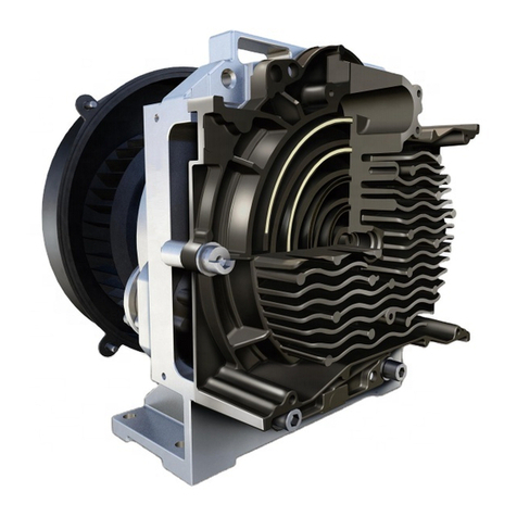
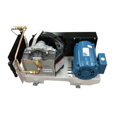
The Powerex Oilless Rotary Scroll Air
Compressor has advanced scroll com-
pressor technology through the devel-
opment of a completely oilless unit.
The Powerex Scroll Compressor offers a
dynamically balanced air end which
insures vibration-free operation. The
rotary design permits a continuous
100% duty cycle. No oil separation, oil
filtration, or inlet valves are required
on the Powerex Scroll unit. The com-
pressor is virtually maintenance free.
Safety Guidelines
This manual contains information that
is very important to know and under-
stand. This information is provided for
SAFETY and to PREVENT EQUIPMENT
PROBLEMS. To help recognize this
information, observe the following
symbols.
Danger indicates
an imminently haz-
ardous situation which, if not avoided,
WILL result in death or serious injury.
Warning indicates
a potentially haz-
ardous situation which, if not avoided,
COULD result in death or serious injury.
Caution indicates a
potentially haz-
ardous situation which, if not avoided,
MAY result in minor or moderate
injury.
!
CAUTION
!
WARNING
!
DANGER
Scroll Enclosure Air Compressors
Notice indicates
important informa-
tion, that if not followed, MAY cause
damage to equipment.
Unpacking
After unpacking the unit, inspect care-
fully for any damage that may have
occurred during transit. Make sure to
tighten fittings, bolts, etc., before
putting unit into service.
Do not operate
unit if damaged
during shipping, handling or use.
Damage may result in bursting and
cause injury or property damage.
PRECAUTIONS DURING TRANS-
PORTATION AND MOVEMENT
TRANSPORTATION BY FORKLIFT
Use openings for forklift under both
sides of the unit.
Avoid damaging
the panel with tips
of the forklift.
TRANSPORTATION BY CRANE
Use openings at the bottom of the unit
and lift up by wire, etc.
Be sure to use pads
in order to protect
panels.
!
CAUTION
!
CAUTION
!
WARNING
NOTICE
IN552001AV 1/02
PURE AIR TECHNOLOGY
Breathable Air Warning
This compressor/pump is NOT
equipped and should NOT be used
“as is” to supply breathing quality
air. For any application of air for
human consumption, you must fit
the air compressor/pump with suit-
able in-line safety and alarm equip-
ment. This additional equipment is
necessary to properly filter and
purify the air to meet minimal
specifications for Grade D breath-
ing as described in Compressed
Gas Association Commodity
Specification G 7.1 - 1966, OSHA 29
CFR 1910. 134, and/or Canadian
Standards Associations (CSA).
DISCLAIMER OF WARRANTIES
IN THE EVENT THE COMPRESSOR
IS USED FOR THE PURPOSE OF
BREATHING AIR APPLICATION
AND PROPER IN-LINE SAFETY
AND ALARM EQUIPMENT IS NOT
SIMULTANEOUSLY USED, EXIST-
ING WARRANTIES ARE VOIDED,
AND POWEREX DISCLAIMS ANY
LIABILITY WHATSOEVER FOR ANY
LOSS, PERSONAL INJURY OR
DAMAGE.
!
DANGER
Description
Figure 1
Figure 2
2
Scroll Enclosure Air Compressors
The compressor nameplate should be
checked to see if the unit is the correct
model and voltage as ordered.
On 10 HP unit
(SED1007) remove
the shipping bracket located inside of
the front panel.
The operator of this compressor must
take the necessary precautions to pre-
vent the level of danger indicated by
these symbols. The operator is also
required to read and understand this
instruction manual and all safety warn-
ings, labels, etc.
Any employer allowing the use of this
compressor in their field of work must
distribute this instruction manual to all
users. The employer must also ensure
all users read, understand and follow
the instructions as described in the
manual, safety warnings, labels, etc.
1. Read and understand
all safety warnings and
instructions before
operating this compres-
sor. Failure to read and
follow all safety warnings may
result in serious personal injury or
death. Property damage and/or
compressor damage may also occur
if all warnings are not followed.
2. Air used for breathing or food pro-
cessing must meet O.S.H.A. 29 C.F.R.
1910.134 or C.F.R. 178.3570 regula-
tions.
Motors, electrical equip-
ment and controls can
cause electrical arcs that
will ignite a flammable gas
or vapor. Never operate or repair in or
near a flammable gas or vapor. Never
store flammable liquids or gases in the
vicinity of the compressor.
3. Safety Valves or Relief Valves used
on this compressor must be in accor-
dance with ANSI/ASME B19 safety
!
WARNING
!
CAUTION
standards. Improperly sized Safety
Valves will result in serious personal
injury or death.
Do not remove the panel
or try to service the air
compressor while the com-
pressor is running or while
the air receiver is under pressure.
Serious personal injury or death will
occur.
4. Never use rubber hoses, plastic pip-
ing or soldered joints in any part of
the compressed air or gas system.
The compressor and system piping
must be compatible.
5. The compressor will shutoff when
the pressure reaches a predeter-
mined maximum pressure. Care
should be used since the compressor
may suddenly restart automatically
when the pressure drops to the pre-
determined minimum pressure.
Never assume the compressor is
ready for service just because the
unit is stopped.
6. All pressure must be drained from
the compressor and the electrical
source must be turned off before
attempting to inspect or repair the
unit.
7. Keep clear of all moving parts espe-
cially if the compressor is operating
with the door panel removed for
inspection or repair.
Do not touch HOT parts of
the compressor such as the
air end, discharge pipe,
aftercooler, motor, etc.
8. Keep flammable gases away from
the compressor. Parts of the com-
pressor become very hot during
operation and the vapors from
flammable gases may cause the unit
to explode.
9. Never use flammable or toxic sol-
vents to clean the compressor or any
of the unit's parts.
10. Do not remove or tamper with any
safety devices, guards, panels or
insulation parts while compressor is
in operation. All guards or panels
!
CAUTION
!
WARNING
must be in place before starting or
operating the compressor.
Install a properly sized
Safety Relief Valve in the
discharge piping ahead of
or before a shut-off valve,
heat exchanger, orifice, etc. The com-
pressor or part of the system could rup-
ture or explode if a Safety Relief Valve
is not installed.
11. Do not change the pressure setting
of the Safety Relief Valve. Do not
replace the Safety Relief Valve with
a plug or restrict the Safety Relief
Valve. The system or the compressor
may be over-pressurized if the
Safety Relief Valve is tampered with
in any way.
12. Do not service the compressor or
any compressor part while the unit
is in operation.
13. Do not remove, disconnect or tam-
per with the High Temperature
Shutdown Switch. The High
Temperature Shutdown Switch must
be installed on the compressor to
protect against high temperatures
damaging the compressor.
14. All electrical connections should be
made by a qualified electrician.
Disconnect all power sup-
plies to the compressor
before opening the electri-
cal box or before servicing the unit.
High voltage may be present.
15. Never remove or alter any safety
warning labels, tags, etc. located on
or provided with compressor.
16. Always provide a clean air source
for your compressor. Keep all piping
direct and short when using an out-
side air source.
17. Locate compressor inlet system
away from possible ingestion of
flammable or toxic vapors, water,
dirty air or air temperatures exceed-
ing 104°F.
18. Never set the pressure to a higher
setting than the one provided from
the factory.
19. Check all gauges daily to be sure the
compressor is operating correctly.
!
WARNING
!
WARNING
Description (Cont)
MANUAL
General Safety
Information
3
Scroll Enclosure Air Compressors
20 Follow all directions for mainte-
nance. Check all safety devices
according to instructions.
21. Never attempt to lift or move the
compressor except when using the
proper lifting procedures.
22. Make sure all electrical components
follow the National Electric code
and all state and local codes when
installing the compressor.
23 Do not operate the compressor if
unusual noise or vibration occurs.
24. Keep all panels in place at all times.
25. Standard motors are not appropri-
ate for dirty, wet or explosive areas.
26. All service should be performed by
trained and qualified people only.
27. The Drive Belt tension should be
checked often during initial opera-
tion of the compressor.
28. Never substitute oil bath or oil wet-
ted filters for the inlet filters provid-
ed with the compressor.
COMPRESSION CYCLE
The Powerex Oilless Rotary Scroll Air
Compressor is based on the theory of
scroll compression. A scroll is a free
standing, intricate spiral bounded on
one side by a solid, flat plane or base. A
scroll set, the basic compression ele-
ment of a scroll compressor, is made up
of two identical spirals which form
right and left hand parts. One of these
scroll components is indexed or phased
180owith respect to the other so the
scrolls can mesh. Crescent-shaped gas
pockets are formed and bounded by
the spirals and the base plate of both
scrolls. As the moving scroll is orbited
around the fixed scroll, the pockets
formed by the meshed scrolls follow
the spiral toward the center and dimin-
ish in size. The moving scroll is prevent-
ed from rotating during this process so
the 180ophase relationship of the
scrolls is maintained. The compressor’s
inlet is at the outer boundary of the
scrolls. The entering gas is trapped in
two completely opposite gas pockets
and compressed as the pockets move
toward the center. The compressed gas
is discharged through the outlet at the
center of the fixed scroll so no valves
are needed.
MAGNETIC STARTER
The magnetic starter on model
SED1007 is located on the right hand
side of the cabinet. For models SET1507
and SEQ2007, the magnetic starter is
located inside the electrical box accessi-
ble from the front panel.
MOTOR OVERLOAD PROTECTION #
The motor overload protection on the
scroll compressor is controlled by an
overload relay which is located beneath
the magnetic starter. Please refer to the
electrical drawings for specifications.
CURRENT SENSOR *
Model SED1007 utilizes current sensors
to prevent motor overload. This device
is located next to the magnetic starter.
CONTROL TRANSFORMER
The control transformer on the scroll
compressor reduces line voltage to 200
volts for operation of the hourmeter,
ventilation fan, circuit board and pres-
sure sensor.
THREE PHASE MOTOR
Powerex three phase motors are TEFC,
NEMA frame motors suitable for 208V,
230V and 460V operation.
TIP SEAL
The tip seal on the scroll compressor is
self-lubricated and allows the unit to
operate efficiently without oil and
expensive filtration. The tip seal should
be replaced every 10,000 hours of oper-
ation.
BEARINGS
The bearings on the scroll compressor
are regreaseable to allow extended
compressor life. Service should be per-
formed every 10,000 hours of opera-
tion.
AIR COOLED AFTERCOOLER
The air cooled aftercooler on the scroll
compressor is a series of deep alloy
cooling fins and a high output cooling
fan. These cooling features allow the
scroll compressor to provide a maxi-
mum discharge air temperature of 60°F
above the ambient temperature.
DRY TYPE INLET FILTER
The inlet filter on the scroll compressor
assures 99% of particulate free air is
admitted to the unit. Change every
2,500 hours or more often in dirty loca-
tions. These filters can be accessed from
the front panel.
COOLING AIR CLEANABLE FILTER
SCREEN
The cooling air cleanable filter screen
on the scroll compressor is located on
the right hand panel (*) or the rear (#)
of the unit and should be cleaned peri-
odically.
DIGITAL HOURMETER
The hourmeter on the scroll compressor
indicates the actual number of total
run hours of all air ends that have been
in operation. The hourmeter is also
used to determine maintenance and
service timing. The hourmeter is acti-
vated when one or more air ends is/are
running.
HIGH TEMPERATURE SHUTDOWN
SWITCH
The high temperature shutdown switch
on the scroll compressor protects the
unit when an unusually high tempera-
ture in the air end is detected. The com-
pressor will shutdown when this high
temperature is detected.
Component
Description
General Safety
Information (Cont)
* - Only available on 10 HP units (SED1007)
# - Only available on 15 & 20 HP units (SET1507, SEQ2007)
Intake section of the duct should
be larger than the dimension of
compressor exhaust shown below:
WIRING
All electrical hook-ups must be per-
formed by a qualified electrician.
Installations must be in accordance
with local and national electrical codes.
1. Use solderless terminals to connect
the electric power source.
2. For 15 - 20 HP remove front panel.
For 10 HP see upper right side of
enclosure, remove rectangle panel.
3. For 15 - 20 HP remove the rectangle
electrical box cover located beneath
air inlet filter on the right front of
the unit.
4. Connect the power inlet cable to
the inlet power junction block locat-
ed on the inlet side of all starter
connections.
Consult your NEC and local codes for
wire size
PIPING
These units do not include air receivers.
Air receiver can be purchased separate-
ly. Please consult our distributors. Use
Chart 2 as a guideline for sizing the air
receiver.
1. Make sure the piping is lined up
without being strained or twisted
when assembling the piping for the
scroll compressor.
2. Appropriate expansion loops or
bends should be installed at the
compressor to avoid stresses caused
by changes in hot and cold condi-
tions.
3. Piping supports should be anchored
separately from the compressor to
4
Scroll Enclosure Air Compressors
INSTALLATION SITE
1. The scroll compressor must be locat-
ed in a clean, well lit and well venti-
lated area. Contaminated area can
clog intake filter and/or intake
metal mesh.
2. The area should be free of excessive
dust, toxic or flammable gases and
moisture.
3. Never install the compressor where
the ambient temperature is higher
than 104oF or where humidity is
high. High humidity will cause elec-
trical short circuit and rusting of
components.
4. Clearance must allow for safe, effec-
tive inspection and maintenance.
24” of clearance for sides, 40” clear-
ance from the top is recommended.
5. If necessary, use metal shims or lev-
eling pads to level the compressor.
Never use wood to shim the com-
pressor.
VENTILATION
1. If the scroll compressor is located in
a totally enclosed room, an exhaust
fan with access to outside air must
be installed.
2. Never restrict the cooling fan
exhaust air.
3. Vent the exhaust air outside to pre-
vent the compressor from operating
at high temperatures and shutting
down.
4. Never locate the compressor where
hot exhaust air from other heat
generating units may be pulled into
the unit.
SUGGESTED VENTILATION SYSTEM
1) The following ventilation capacity
is designed to keep the tempera-
ture rise inside the room to be max.
10°F. Since the calculation is based
on zero static pressure, the actual
ventilation capacity should be larg-
er than the figure in Chart 1.
2) Install the exhaust duct in order to
minimize the pressure lost of the
ducting. Keep the distance
between the inlet duct and the
compressor exhaust to be at least
12 inches for ease of maintenance.
reduce noise and vibration.
4. Never use any piping smaller than
the compressor connection.
5. Use flexible hose to connect the
outlet of the compressor to the pip-
ing so that the vibration of the
compressor does not transfer to the
piping.
SAFETY VALVES
Tank mounted compressors are shipped
from the factory with safety valves
installed in the air receiver manifold.
The flow capacity of the safety valve is
equal to or greater than the capacity of
the compressor.
1. The pressure setting of the safety
valve must be at least 10 psi less
than the maximum working pres-
sure of the air receiver.
2. Safety valves should be placed
ahead of any possible blockage
point in the system, i.e. shutoff
valve.
3. Avoid connecting the safety valve
with any tubing or piping.
4. Manually operate the safety valve
every six months to avoid sticking or
freezing.
BEFORE START UP
1. Make sure all safety warnings,
labels and instructions have been
read and understood before contin-
uing.
2. Remove any shipping materials,
brackets, etc.
3. Confirm that the electric power
source and ground have been firmly
connected.
4. Check the belts for tightness.
5. Be sure all pressure connections are
tight.
6. Check to be certain all safety relief
valves, etc., are correctly installed.
7. Securely mount all panels and
guards.
8. Check that all fuses, circuit breakers,
etc., are the proper size.
9. Make sure the inlet filter is properly
installed.
10. Confirm that the drain valve is
closed.
Operation
Ventilation 2825 3885 5300
Capacity (cfm)
Exhaust Dimension for all Models
13" x 5.6"
Model 10 HP 15 HP 20 HP
Installation
Chart 1
10 20 gallons
15 30 gallons
20 40 gallons
HP Air Receiver Min. Capacities
Chart 2
5
Scroll Enclosure Air Compressors
11. Visually check the rotation of the
compressor pump. The rotation
should be counterclockwise if
viewing the compressor from the
pulley or belt side of the motor or
the air end. If the rotation is incor-
rect, have a qualified electrician
correct the motor wiring.
START-UP AND OPERATION
1. Follow all the procedures under
“Before start-up” before attempt-
ing operation of the compressor.
2. Switch on the electric source
breaker.
3. Make sure electric source lamp
lights up and that the caution
code or alarm code does not show
up on the display on the PLC.
Note: The alarm lamp light will come
on if a temperature sensor is not con-
nected. If the sensor is not connected,
have a qualified service person recon-
nect the sensor.
4. Open the discharge valve com-
pletely.
5. Push ON button and check that
the compressor operates without
excessive vibration, unusual noises
or leaks.
6. Close the discharge valve com-
pletely.
7. If the pressure does not rise on
a three phase unit, turn the
unit off. Have a qualified elec-
trician switch the breaker OFF
and exchange the L1and L2
connections (two out of three
phases of electric source)
inside the magnetic switch.
8. Check the discharge pressure. Also
make sure the air pressure rises to
the designated pressure setting by
checking the discharge pressure
gauge.
Control Logic: Since these compres-
sors are designed using multiple air-
ends, they are using multiplex con-
troller. The controller will start and
stop each air-end according to the
pressure and air consumption.
10HP CONTROLLER (SED1007)
1) 10HP unit consists of two air ends.
One is the lead air end, and the other
is the lag air end. These two units will
alternate every 30 running minutes
(this default value can be changed,
see instruction on "Set Mode".
2) After the ON button is activated,
both air end will start and pressure
gauge on the control panel rises.
3) When the pressure reaches 107.6 psig
the lag air end will stop. When the
pressure rises reaches 113.1 psig the
lead air end will also stop.
4) As the discharge pressure drops down
to 100.3 psig the lead air end will
start again. The lag air end will start
when the pressure drops down to
93.0 psig.
5) The status of each air end can be
monitored from the control panel.
15 AND 20HP CONTROLLER (SET1507,
SEQ2007)
1) Alternating Control:
The controller will equalize the oper-
ating hours on each air-end. It will
alternate between the air end with
the most running time and the air
end with the lowest running time.
2) Prevention of long term operation:
When an air-end has been operating
longer than the set-time, the con-
troller will alternate to the air-end
with the lowest running time. This
will prevent one air end from running
continuously for too long and will
equalize the running time between
the available air ends.
SHUT-DOWN
1. Stop the compressor by pushing the
OFF button.
NOTE: If the compressor rotates in
reverse for more than five seconds, the
check valve needs to be cleaned or
replaced.
2. Switch the breaker OFF if the com-
pressor is not to be used for a long
period of time.
STOPPING THE COMPRESSOR DURING
NORMAL OPERATION
1. Close the discharge valve.
2. Allow the air pressure to build and
the compressor to stop.
3. Turn the compressor off by pushing
the OFF button.
STOPPING THE COMPRESSOR DURING
EMERGENCY OPERATION
1. Stop the compressor by pushing the
OFF button or by turning the power
off at the main disconnect panel.
Explanation of operating panel:
Bottom Unit Light*: Lights up when it
displays information on bottom air end.
Top Unit Light*: Lights up when it dis-
plays information on top air end.
Comp. Operating Lamp: Lights up
when ON switch is pushed.
Operation (Cont)
Figure 3 - Operating Panel
Operating Panel
Reset Switch
Mode Selector
Switch
Item Selector
Switch
Stop Switch
ON Switch
Comp.
Operating
Lamp
Display
Bottom Unit
Light*
Top Unit
Light*
Display Selector
Switch
Mode Display
Light
* - Only available on 10 HP units (SED1007)
# - Only available on 15 & 20 HP units (SET1507, SEQ2007)
6
Scroll Enclosure Air Compressors
Display Selector Switch: Selects
display of top or bottom air end.
Items Selector Switch: Selects the
information to be displayed.
Mode Display Light: Indicates
selected display mode.
Mode Selector Switch: Selects the
mode to be displayed.
ON Switch: Starts the unit.
Reset Switch: Performs various
resettings.
Stop Switch: Stops the unit.
DISPLAY MODE
There are four modes of display:
Normal, Caution, Emergency Stop and
Setup.
1. NORMAL MODE (Default Mode) -
To toggle between display, push
item selector switch. You can
obtain operating information
(pressure, current, temperature,
hours, operating conditions) which
are useful for daily maintenance
and inspection. It functions
whether compressor operates or
stops. (See Chart 3).
2. CAUTION MODE - In order to
select Caution Mode, push Mode
Selector Switch so that Caution
Mode light is illuminated. By Item
Selector Switch, you can determine
causes and conditions when prob-
lems occur as indicated in Chart 4.
It functions only when compressor
stops.
Operating Panel
(Continued) Pressure Shows outlet pressure of compressor in psig. (Display
on the left means 78 psig.)
Current* Shows current in ampere. (This display means 14A.)
Display selector switch selects display of top or bottom
air end.
Temperature* Shows temperature of air end in °C, (This display means
58°C.) Display selector switch selects display of top or
bottom air end.
Operating Shows operating time in x 10 hours. (This display
Time means 230 hours.)
Operating Shows operating condition of top and bottom air ends
Conditions* and their relationship.
Operating Displays the present operating conditions of air end No.
Conditions# 1 through No. 4. From left to right, they indicate air
end No. 1 • 2 • 3 • 4.
In the above example, air end No. 1 and No. 3 are in
operation, air end No. 2 is in emergency stop and air
end No. 4 is not operating.
Since SET1507 has not air end No. 4 the far right dis-
play will always be underlined.
Chart 3 - Display Selection
Item Display Contents
Caution Shows the Caution Code.
Code (Refer to Chart 5 regarding details.)
Pressure Shows Pressure in psig when caution displays. (Display
means 78 psig.)
Current* Shows Current in ampere when caution displays. (This
display means 19A.)
Temperature Shows Temperature of air end in °C when caution dis-
plays. (This display means 58°C.) When air end temper-
ature is less than 15°C or other failure like cut of tem-
perature sensor occurs, displays.
Operating Shows Operating Time in x 10 hours when caution
Time displays. (This display means 230 hours.)
Operating Shows Operating Mode in number when caution
Mode occurs. (Refer to Chart 9 for Operating Mode.)
Chart 4 - Caution Mode
Item Display Contents
* - Only available on 10 HP units (SED1007)
# - Only available on 15 & 20 HP units (SET1507, SEQ2007)
*
#
2nd Set (Top)
Means That It
Stops
Means Lead Air End
1st Set (Bottom)
O Means In Operation
Means emergency
when “hyphen”
lights up
means in
operation
Compressor stops
when “underline”
lights up.
7
Scroll Enclosure Air Compressors
3. EMERGENCY STOP MODE - In
order to select Emergency Stop
Mode, push Mode Selector Switch
so that Emergency Stop Mode
light is illuminated. By Item
Selector Switch, you can determine
causes and conditions when prob-
lems occur, as indicated in Chart 6.
It functions only when compressor
stops.
Operating Panel
(Continued)
Chart 6 - Emergency Stop Display Mode
* - Only available on 10 HP units (SED1007)
# - Only available on 15 & 20 HP units (SET1507, SEQ2007)
Emergency Shows causes for emergency code numbers.
Code Number (Refer to Chart 7 regarding details.)
Pressure Shows Pressure in psig when emergency stops occur.
(Display means 78 psig.)
Current* Shows Current in ampere when emergency stop dis-
plays. (This display means 25A.)
Temperature Shows Temperature of air end in °C when emergency
stop occurs. (This display means 58°C.) When air end
temperature is less than 15°C or other failure like cut
of temperature sensor occurs, displays.
Operating Shows Operating Time in x 10 hours when emergency
Time stop occurs. (This display means 230 hours.)
Operating Shows Operating Mode in number when emergency
Mode stop occurs. (Refer to Chart 9 for Operating Mode.)
Item Display Contents
*
#
Emergency Code No. Description
AL 21 Sudden temperature rise of air end
AL 22 High temperature of air end
AL 31* Sudden rise of current
AL 32 High current
AL 33* Low current
AL 91 Maintenance time 1: Intermediate inspection and maintenance.
Refer to page 9.
AL 92* Maintenance time 2: Intermediate inspection and maintenance.
Refer to page 9.
Chart 7 - Emergency Code Number
Caution Code Description
CA 21 High temperature of air end
CA 22 Failure of temperature sensor
CA 31 High current
CA 91 Maintenance time 1: Intermediate inspection and maintenance.
Refer to page 9.
CA 92* Maintenance time 2: Intermediate inspection and maintenance.
Refer to page 9.
Chart 5 - Caution Code
8
Scroll Enclosure Air Compressors
4. SET MODE - Push Mode Selector
Switch so that Set Mode light is
illuminated. Item Selector Switch
can show each of the set contents
as shown in Chart 8. It functions
only when compressor stops.
CHANGING MINIMUM AND MAXI-
MUM PRESSURE SETTING
See Figure 4.
1. Change to Set Mode by utilizing
Mode Switch.
2. Display maximum pressure or mini-
mum pressure by utilizing Item
Switch.
3. You can decrease set pressure by
pushing OFF button and Item
Button at the same time.
4. You can increase set pressure by
pushing Off button and Mode
Button at the same time.
Restrictions:
• Maximum pressure does not
exceed figure initially set at our
plant.
• Pressure difference between maxi-
mum and minimum pressure is14.5
psig or over.
• Minimum pressure is 29 psig.
* The display will round all pressure
increments to the nearest psi.
Operating Panel
(Continued) Max. Pressure Shows Max. Set Pressure in psig. (This display means
116 psig.)*
Min. Pressure Shows Min. Set Pressure in psig. (This display means 93
psig.)*
Time to Shows Time to Change Operating Air End and prevents
Change the same air end from operating for a long time. 1 on
Operating Air display means 15 minutes. (This display means 2 x 15
End minutes - 30 minutes.)
External means that external operation is set.
Operation means that external operation is canceled.
(When either displays, it can be changed by pushing
reset switch.)
External Shows set situation of external output.
Output displays when emergency stop occurs.
displays when emergency stop or caution
occurs. (When either displays, it can be changed by
pushing reset switch.)
Maintenance Shows remaining time till intermediate maintenance
Time 1 and inspection in terms of 10 hours. The first figure is
980 (9800 hours) and decreases as operating time
becomes longer.
Group Control Shows set situation of Group Control.
means that Group Control mode OFF is set.
means that Group Control mode ON is set.
(When either displays, it can be changed by pushing
reset switch.)
Chart 8 - Set Mode
Item Display Contents
9
Scroll Enclosure Air Compressors
1. When Caution is being signalled
by the unit, caution number
shown in Chart 5 flashes on display
section (compressor does not stop).
When caution condition goes
away, display will stop flashing
and the latest caution information
is being memorized inside the
printed circuit board.
2. You can check caution information
by going to Caution Display Mode.
3. When caution occurs, cut off cir-
cuit breaker, solve the problem
and switch on breaker again.
Caution condition will be can-
celled.
CA 21: Temperature of air end is high
- When the temperature of air end
becomes high, CA 21 will be dis-
played. See Chart 10.
CA 22: Failure on temperature sensor -
See Chart 11.
CA 31: Current is High - When current
is high, CA 31 is displayed. See
Chart 12.
CA 91, CA 92: Intermediate
Maintenance and Inspection - It
shows that maintenance time
(remaining time to intermediate
maintenance and inspection) is 0.
Refer to Set Mode on page 8 for
details. It is time for grease up,
replacement of tip seal, etc.
Contact our distributor and ask
them to do intermediate mainte-
nance and inspection.
Caution Signal Operating Mode Operating Situation
d 110 Initial stage of stop
d 111 Normal stop
d 112 Dryer preliminary start-up
d 120 Initial stage of start
d 121 Start 1
d 122 Start 2
d 130 Initial stage of load
d 131 Normal load
Chart 9 - Detail of Operating Mode
Item Causes
Ambient temperature Ambient temperature is high
Failure of cooling 1. Intake metal screen is clogged
2. Exhaust outlet is clogged
3. Aftercooler fins are dirty
4. Defective exhaust fan on compressor side.
5. Damaged intake hose
6. Cooling passage of compressor is clogged
Chart 10 - Troubleshooting Guide: CA 21
Item Causes
Sensor 1. Temperature sensor cords are not properly connected
2. Temperature sensor cords are cut
3. Defective temperature sensor
Ambient temperature When it is less than about 10°C
Chart 11 - Troubleshooting Guide: CA 22
Item Causes
Electric source 1. R phase or T phase is not connected well
2. Voltage is unstable
3. Deterioration of wiring
4. Low voltage
Exhaust pressure too high 1. Set pressure is wrong
2. Pressure sensor cord is disconnected or is not contacted
3. Defective pressure sensor
4. Clogged control piping due to freezing
Air end Failure
Electric motor Failure
V belt Tension is too tight
Chart 12 - Troubleshooting Guide: CA 31
Caution
Troubleshooting
Guide
10
Scroll Enclosure Air Compressors
1. In case of emergency stop, emer-
gency (alarm) code shown in Chart
7 flashes on display section and
the associated compressor (air end)
will stop. The normal air end with
no problem continues to operate.
2. You can check the emergency
information by going to
Emergency Display Mode.
3. In case of Emergency Stop, study
the information, find the cause
and take necessary measures. Then
push Reset Switch on operating
panel to cancel flashing emer-
gency number. If you cannot find
a reason or remedy, consult with
our technical service team or our
service centers.
AL 21: Sudden temperature rise of air
end
AL 22: Temperature rise of air end
If the temperature rises more than set
temperature, compressor (air end)
stops. See Chart 13.
AL 31: Sudden rise of current
AL 32: Rise of current
If current becomes very high, AL 31 or
AL 32 displays and compressor stops.
See Chart 14.
AL 33: Low motor current - If motor
current becomes very low, AL 33
displays and the compressor stops.
Open phase of S phase is consid-
ered to be a cause.
AL 91 and AL 92: Intermediate main-
tenance and inspection is over - If
you do not conduct intermediate
maintenance when your compres-
sor reaches its time and continue
operation for a further 200 hours
with CA 91 or 92 not canceled, and
stop operation; AL 91 or AL 92 will
Emergency (Alarm)
Signals
Item Causes
Ambient temperature Ambient temperature is high
Failure of cooling 1. Intake metal screen is clogged
2. Exhaust outlet is clogged
3. Aftercooler fins are clogged
4. Defective exhaust fan on compressor side.
5. Damaged intake hose
Chart 13 - Troubleshooting Guide: AL 21 and AL 22
Emergency
Troubleshooting
Guide
Item Causes
Electric source Open phase of R or T phases, low voltage
Air end Failure
Electric motor Failure
Chart 14 - Troubleshooting Guide: AL 31 and AL 32
display when you switch on circuit
breaker again.
When AL 91 or AL 92 displays, contact
our distributor and ask them to do
the intermediate maintenance and
cancel AL.
As a temporary measure, you can
continue operation by pushing reset
switch, but the manufacturer is not
responsible for any failure or problem
after AL 91 or AL 92 displays.
When AL 91 or AL 92
displays, contact our
distributor and do the intermediate
maintenance and inspection soon.
!
CAUTION
11
Scroll Enclosure Air Compressors
Noise
Air Discharge Level
Discharge Delivery Compressor Air Discharge (1.5m
Model Air Control Pressure (SCFM @ Speed Driving Temp. Air from
Number End System (PSIG) 100 psig) (RPM) System °F Outlet front)
SED1007 SLAE05 Solid State 95-115 29.4 3150 V-belt < Intake 3/4” 53
Pressure temp. +58°F
Driven
Control
SET1507 SLAE05 Solid State 95-115 44.1 3150 V-belt < Intake 1” 56
Pressure temp. +54°F
Driven
Control
SEQ2007 SLAE05 Solid State 95-115 58.8 3150 V-belt < Intake 1” 58
Pressure temp. +58°F
Driven
Control
Specifications
Compressor
Motor
Model Starting Overload High Temp. Dimensions
Number Type Horsepower Voltage System Relay Shut Down (W x L x H)
SED1007 3 Phase, TEFC 10 (2 x 5) 208 - 230/460 Magnetic Current Installed 25 x 24.2 x 49.6
starter sensor
SET1507 3 Phase, TEFC 15 (3 x 5) 208 - 230/460 Magnetic Installed Installed 28.3 x 44 x 62.6
starter
SEQ2007 3 Phase, TEFC 20 (4 x 5) 208 - 230/460 Magnetic Installed Installed 28.3 x 44 x 62.6
starter n
Chart 15 - Specifications for Compressors and Motors
12
Scroll Enclosure Air Compressors
Maintenance Schedule
Operating Hours
Item Action needed 500 2500 5000 10,000 20,000 Remarks
Intake Filter Clean, replace ●▲
Ventilation Screen Clean ●
Air End/
Blower Fan Clean ●
Fan Duct Clean ●
Compressor Fins Clean ●
Compressor Grease ▲▲Use genuine Powerex grease
Tip Seal Replace ▲
Dust Seal Inspect, replace ●▲
V-belt Inspect, replace *Readjust ●▲
Temperature Sensor Confirm operation ●
Pressure Sensor Confirm operation ●
Current Sensor Confirm operation ●
Magnetic Starter Inspect ●Replace if contact
points deteriorated
Check Valve Replace ▲
Safety Valve Confirm operation ●
Ventilation Fan Inspect ●●Replace if malfunctions
Pulley Inspect groove ●Repair if abnormal wear is
detected
Motor Inspect ● ● Replace if abnormal noise is
detected
Intake Hose Replace ▲
Air Hose Inspect, replace ●▲
After Cooler Clean outside ●●
O-Ring Replace ▲
Operating Panel Inspect monitor
display Daily
Piping Inspect for leakage ●●
Compressor Overhaul ●▲Consult factory
●Inspect
▲Replace
NOTES:
1. Inspect and perform maintenance periodically according to maintenance schedule.
2. The maintenance schedule relates to the normal operating conditions. If the circumstances and load condition are adverse,
shorten the cycle time and perform maintenance accordingly.
3. * Marked “Readjust” means the tension of the V-belt should be adjusted during the initial stage and inspected every 2,500
hours afterwards.
Chart 16
13
Scroll Enclosure Air Compressors
Scheduled
Maintenance
INTAKE FILTER
1. Remove the front panel of the unit.
2. Remove the air inlet housing, the
wing nut and the inlet filter ele-
ment.
3. Clean the inlet filter element with
compressed air or replace with a
new element.
NOTE: Never clean filter element with
solvents or water.
VENTILATION SCREEN
1. Remove the ventilation screen
located at the rear of the unit (#) or
the right hand panel (*).
2. Clean with compressed air or soap
and water, if necessary.
INSPECT V-BELT TENSION
1. Check V-Belt tension with tension
gauge.
2. Adjust to the specifications listed in
Chart 17.
GREASE COMPRESSOR BEARINGS
1. Remove the plastic dust cap (Key
#69) from the air end. See Figure 4.
2. Move the compressor pulley until
the grease fitting is visible through
the dust cap hole.
3. Use a grease gun extension adapter
to engage the grease fitting and
supply the proper volume of grease
as indicated on the grease delivery
chart. See Chart 18.
Use only Powerex
genuine grease.
(Part # IP600000AV). Pump grease gun
before feeding to eliminate air from
grease passage of the needle adapter.
GREASE PIN CRANK BEARING
1. Remove the V-Belt and the fan
cover (Key #24).
2. Remove the air end pulley with a
gear puller.
3. Remove the fan duct (Key #22).
4. Remove the three grease caps (Key
#72). Do not attempt to loosen or
tighten the bolt (Key #71).
5. Grease all three pin crank bearings.
!
CAUTION
Model New Belt Load ± Deflection Existing Belt Load ± Deflection
Kg / 10 mm Kg / 10 mm
SLP05 6 ± 0.5 5.5 ± 0.5
Chart 17
SLP05
Bearing 1st TIme 2nd Time
O.S. Bearing 6 times 4 times
Pin Crank Bearing O.S. Side 6 times 4 times
Pin Crank Bearing Housing Side 6 times 4 times
Chart 18 - Grease Delivery
Use only Powerex genuine grease, (Part
#IP600000AV), or equivalent.
NOTE: Each pump of the grease gun equals 0.65g of grease.
The volume of grease is less after the 2nd pump since some
of the grease supply will remain in the grease passage.
!
CAUTION
The grease fitting,
located in the cen-
ter of the pin crank bearing, feeds only
the orbit scroll side bearing. Use a nee-
dle adapter to supply grease to the
housing side bearing. Pump grease gun
before feeding to eliminate air from
grease passage of the needle adapter.
Hold grease gun for 5 - 10 seconds after
feeding to prevent grease blowback
from the grease fitting.
!
CAUTION
Figure 4 - Air end. To locate the grease fitting on the counter weight, place the
key way on the crankshaft as shown.
45°
Grease
Fitting
Grease Gun
Extension
Adapter
Counter
Weight
Key
Way
Plastic
Dust Cap
Scheduled
Maintenance (Cont)
14
Scroll Enclosure Air Compressors
REPLACE TIP SEAL
1. Remove the six nuts (Key #60).
2. Remove the stationary scroll housing
(Key #1).
3. Take out the old tip seal from the
orbiting scroll housing and stationary
scroll housing.
4. Remove the old dust seals from both
housings.
Install the new tip seals and dust seals in
the stationary and orbiting scroll hous-
ings in the following manner:
1. Blow off any dust from both scroll
housings.
2. Install the high pressure, or shorter
tip seal, from the center of the scroll
and extend the tip seal outward in
the seal channel.
NOTE: The side and bottom lip notches
face inward and down into the channel.
3. Install the low pressure, or longer tip
seal, in the same way, but make sure
there is no gap between the high and
low pressure seals.
Do not attempt to
remove the orbit
scroll from the housing.
After installing half
of the low pressure
seal, carefully remove the seal from the
channel and make sure the seal is prop-
erly locking onto the channel indenta-
tions located just past the high pressure
seal.
NOTE: The indentations are machined
into the seal channel to prevent the low
pressure seal from moving.
4. Blow off any dust caused by remov-
ing the seal from the seal channel.
5. Install the low pressure seal com-
pletely. Make sure the side and bot-
tom lip notches are facing inward
and down into the seal channel.
NOTE: The lip notches must not be dis-
torted in the seal or torn off.
!
CAUTION
!
CAUTION
6. Install backup tube in the dust seal
channel.
7. Place dust seal over the backup tube.
The backup tube
must meet at the bot-
tom of the housing in the six o'clock
position. The dust seal must meet on the
right side of the housing, or in the three
o'clock position.
!
CAUTION
Figure 5
Extension
Adapter
PC - Orbit Scroll
Side Bearings
Grease Fitting
PC - Housing
Side Bearings
Grease
Gun
3 Grease Caps
Air End Pulley & Cooling
Fan (Not Shown)
Fan Duct Shroud
(Not Shown)
8. Install the stationary scroll housing
onto the orbiting scroll housing
and reassemble the unit.
9. Make sure when reassembling the
unit, the Pulley Belt and the
Housing Nut follow the specifica-
tions as detailed in Chart 19 below.
Figure 6
Extension
Adapter
Needle
Adapter
PC - Orbit Scroll Side Bearings
Grease Fitting
PC -
Housing
Side
Bearings
Pulley Belt Housing Nut
Key #65 Key #60
Model Size Torque Size Torque
SLP03 M8 175 M8 175
SLP05 M8 175 M10 260
Chart 19 - Belt Torque (In. - lbs.)
15
Scroll Enclosure Air Compressors
Electrical Diagram - SED1007 (10 HP)
Figure 7
208-230/460V 60 Hz
F Fuse Compressor
J Modular jack Compressor
Fan 1,2 Exhaust fan Compressor
PS Pressure sensor Compressor
TH2 Temperature sensor Compressor
TH1 Temperature sensor Compressor
CT2 Current sensor Compressor
CT1 Current sensor Compressor
MC2 Magnet contactor Compressor
MC1 Magnet contactor Compressor
MOTOR2 Motor Compressor
MOTOR1 Motor Compressor
TRANS Transformer for Compressor
PCB
EXB Expansion PCB Compressor
DB Display Board Compressor
MB Main PCB Compressor
16
Scroll Enclosure Air Compressors
Electrical Diagram - SET1507 (15 HP)
Figure 8
3Ø 208-230/460V 60 Hz
PCR Power relay
FC Fan controller
R Relay
FM Fan motor
SW Selector switch (3 notches)
NF Noise filter
F Fuse
J Modular jack
FAN1, 2 Ventilation fan
PS Pressure sensor
TH3 Temperature sensor
TH2 Temperature sensor
TH1 Temperature sensor
OCR3 Thermal relay
OCR2 Thermal relay
OCR1 Thermal relay
MC3 Magnet contactor
MC2 Magnet contactor
MC1 Magnet contactor
MOTOR3 Motor
MOTOR2 Motor
MOTOR1 Motor
TRANS Transformer for PCB
EXB Expansion PCB
DB Display board
MB Main PCB
Figure 9
17
Scroll Enclosure Air Compressors
Electrical Diagram - SEQ2007 (20 HP)
3Ø 208-230/460V 60 Hz
PCR Power relay
FC Fan controller
R Relay
FM Fan motor
SW Selector switch (3 notches)
NF Noise filter
F Fuse
J Modular jack
FAN1, 2 Ventilation fan
PS Pressure sensor
TH4 Temperature sensor
TH3 Temperature sensor
TH2 Temperature sensor
TH1 Temperature sensor
OCR4 Thermal relay
OCR3 Thermal relay
OCR2 Thermal relay
OCR1 Thermal relay
MC4 Magnet contactor
MC3 Magnet contactor
MC2 Magnet contactor
MC1 Magnet contactor
MOTOR4 Motor
MOTOR3 Motor
MOTOR2 Motor
MOTOR1 Motor
TRANS Transformer for PCB
EXB Expansion PCB
DB Display board
MB Main PCB
18
Figure 10 - SED1007
Scroll Enclosure Air Compressors
19
Scroll Enclosure Air Compressors
Figure 11 - SET1507
20
Scroll Enclosure Air Compressors
Figure 12 - SEQ2007

This manual suits for next models

2

Other Powerex Air Compressor manuals

Powerex OTD Series User manual

Powerex

Powerex OTD Series User manual

Powerex SED1007E User manual

Powerex

Powerex SED1007E User manual

Powerex SES02 User manual

Powerex

Powerex SES02 User manual

Powerex SBBSS030020SD09 Installation and operation manual

Powerex

Powerex SBBSS030020SD09 Installation and operation manual

Powerex SED1007 User manual

Powerex

Powerex SED1007 User manual

Powerex SLAE03E Installation and user guide

Powerex

Powerex SLAE03E Installation and user guide

Powerex SE Series Installation and operation manual

Powerex

Powerex SE Series Installation and operation manual

Powerex Simplex AS-007 User manual

Powerex

Powerex Simplex AS-007 User manual

Powerex SED1007HP User manual

Powerex

Powerex SED1007HP User manual

Powerex AS-XXX User manual

Powerex

Powerex AS-XXX User manual

Powerex PMAC User manual

Powerex

Powerex PMAC User manual

Powerex OTD110 User manual

Powerex

Powerex OTD110 User manual

Powerex SLAE03EB Installation and user guide

Powerex

Powerex SLAE03EB Installation and user guide

Powerex ad series User manual

Powerex

Powerex ad series User manual

Powerex SBS Series User manual

Powerex

Powerex SBS Series User manual

Powerex SBS0307 User manual

Powerex

Powerex SBS0307 User manual

Popular Air Compressor manuals by other brands

Kellogg-American V120101-452 instruction manual

Kellogg-American

Kellogg-American V120101-452 instruction manual

Bitzer OLC-D1-S technical information

Bitzer

Bitzer OLC-D1-S technical information

GÜDE 275 PRO Translation of the original instructions

GÜDE

GÜDE 275 PRO Translation of the original instructions

Vixen Horns VXO4841C installation guide

Vixen Horns

Vixen Horns VXO4841C installation guide

paasche D200 Instructions and parts list

paasche

paasche D200 Instructions and parts list

LUBCON Compguard FG 32 instructions

LUBCON

LUBCON Compguard FG 32 instructions

Schneider Airsystems UNM 410-10-50 DX operating manual

Schneider Airsystems

Schneider Airsystems UNM 410-10-50 DX operating manual

Clarke RANGER 30 air Operating & maintenance instructions

Clarke

Clarke RANGER 30 air Operating & maintenance instructions

DeWalt DCC1054N-XJ instructions

DeWalt

DeWalt DCC1054N-XJ instructions

Craftsman 919.167280 owner's manual

Craftsman

Craftsman 919.167280 owner's manual

Coltri Sub POLARIS Use and maintenance manual

Coltri Sub

Coltri Sub POLARIS Use and maintenance manual

QED MP40 Assembly guide

QED

QED MP40 Assembly guide

VIAIR 100C quick start guide

VIAIR

VIAIR 100C quick start guide

General International AC1103 operating manual

General International

General International AC1103 operating manual

BUSCH DOLPHIN LN 3001 A Installation and operating instructions

BUSCH

BUSCH DOLPHIN LN 3001 A Installation and operating instructions

Bostitch BTFP02011 Operation and maintenance manual

Bostitch

Bostitch BTFP02011 Operation and maintenance manual

North Star M459231B.1 Installation, operation and maintenance

North Star

North Star M459231B.1 Installation, operation and maintenance

Draper 65958 instructions

Draper

Draper 65958 instructions

manuals.online logo
manuals.online logoBrands
  • About & Mission
  • Contact us
  • Privacy Policy
  • Terms and Conditions

Copyright 2025 Manuals.Online. All Rights Reserved.