Stratus T401 User manual

Stratus
Customer Service
Documentation
HI-030070


1T401 Tape Drive Installation Instructions
ThemodelT401StratuscartridgetapedriveisanIBM3480mediacompat-
ible unit manufactured by Fujitsu. It is mounted in a Universal Expansion
Cabinet with an external door extension frame. This high density storage
tape drive is designed to provide on–line unattended backup.
The T401 is a 1/2–inch cartridge tape drive with 18 data recording tracks.
The tape speed is 2 m/s with a data transfer rate of approximately 370 KB/s
fromsystemtoformatterunderVOS10.2(450KB/sunderVOS11.0). The
T401 is available in two configurations: single and dual drive assemblies.
•Utilizesan automaticloader, which holds up to 10 car-
tridges, on each drive assembly.
•Has a storage capacity of 200 MB per cartridge (2 GB
per drive assembly).
•Uses a Formatter (Controller) with a SCSI interface
connecting to a K122 IOA (K116 for initial release).
•Employs current tape commands and can be used as a
boot device.
•Has built–in comprehensive self–diagnostics.
•No operational maintenance required except periodic
cleaning of the tape path with a cleaning cartridge.
Extension
Frame
Access Door
1x2 Drive
Assembly
Formatter Extension Frame
10–Cartridge
Magazine
Autoloader
Overview
Description

2T401 Tape Drive Installation Instructions
T401 model numbers are given in the table below.
Model Model Number
Single Drive Assembly (1x1) T401–1
Dual Drive Assembly (1x2) T401–2
Thefollowing tables list functional, physical, environmental, and electrical
specifications for the T401 tape drive.
Functional
MTBF (Tape Drive) 22,500 hrs.
MTBF (Formatter) 70,000 hrs.
Number of data recording tracks 18
Recording format GCR (DD–NRZI)
Recording density 37,871 Bpi
Data Capacity 200 MB/cartridge
Tape Speed 2 m/s
Load Time Approx. 8 sec
Unload time (from BOT) Approx. 7 sec
Rewind time (from EOT to BOT) Approx. 48 sec
Formatter Buffer Size 2 MB
Physical
Height
Tape Drive Assembly 5.25 inches (125 mm)
Formatter 3.5 inches (88.9 mm)
Width 19 inches (482.6 mm)
Depth (overall) 33.5 inches (837.5 mm)
Weight
Formatter 46 lbs. (22 kg)
1x1 Tape Drive Assembly 68 lbs. (30.8 kg)
1x2 Tape Drive Assembly 115 lbs. (52 kg)
Magazine 11 lbs. (5 kg)
T401 Tape Drive
Models
Specifications
Functional
Specifications
Physical Specifications
3T401 Tape Drive Installation Instructions
Environmental
Operating temperature 41–90oF (5 to 32oC)
Non–operating temperature 32–120oF (0–49oC)
Operating relative humidity 20–80% non–condensing
Non–operating relative humidity 0–95% non–condensing
Operating max. wet bulb temperature 78oF (26oC)
non–condensing
Non–operating max. wet bulb
temperature 80oF (27oC)
non–condensing
Electrical
Tape drive assembly
power supply +24V +10% -5% 4.0A
+12V +/-7% 2.0A
+5V +/-5% 5.0A
-5.2 V +/-5% 3.0A
Formatter Power Input 100–120 Vac 4A
200–240 Vac 2A
Environmental
Specifications
Electrical
Specifications
4T401 Tape Drive Installation Instructions
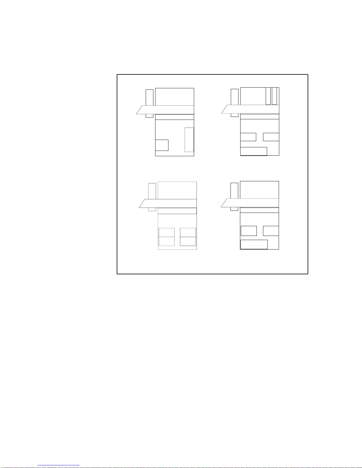
Four configurations of the expansion cabinet are currently supported.
Power
Tray
D117
D20X
T401 Drive Assembly
Formatter Formatter
Formatter Formatter
U201
CIU
D117
D20X
IOP
D20X
IOP
D20X
IOP
D20X
IOP
D20X
IOP
D20X IOP
D20X
D
1
2
6
D
1
2
6
IOA
T401 Drive Assembly
T401 Drive Assembly T401 Drive Assembly
PK 54 Cabinet E100-50 Cabinet
E100-50 CabinetE100-50 Cabinet
U201
CIU
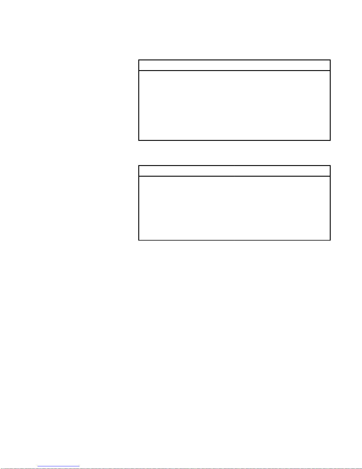
Each T401 model contains a single Formatter unit that controls the transfer
of read/write data commands between the Stratus processor and the tape
drive. In the 1x2 model, the Formatter controls both drives which are
connected in daisy chain.
A control data cable (digital), which transfers the command and write data,
is connected from the Formatter to the first (or only) drive which is Drive 0.
A read data cable (analog) is also connected from the Formatter to Drive 0.
A dc power control cable is connected from the PCI connector on the
Formatter to the PCI connector on the Drive 0 power supply. A SCSI cable
is connected from the SCSI IN interface on the Formatter to the K122 IOA
and a terminator is installed on the SCSI OUT interface. In the 1x2 model,
the second drive (Drive 1) is daisy chained to the first by connecting a
second power control cable from the PCO connector on the Drive 0 power
supply to the PCI connector on the Drive 1 power supply.
Expansion Cabinet
Configurations
Cable Connections

5T401 Tape Drive Installation Instructions
NOTE: A 1x1 Drive Assembly consists of a drive, a power
supply, an auto loader, and drive cables. A 1x2 Drive
Assembly contains two drives, two power supplies, two auto
loaders, and drive cables.
Drive 0 Drive 1
PCI PCO PCI
To K122 IOA
SCSI IN
SCSI
OUT
(Term–
inated)
DC power
Control
Cable
AC Power
Cords
AC
Power
Cord
Digital
Cable
Analog
Cable
SCSI
Cable
The following table contains Stratus part numbers for T401 Field
Replaceable Units (FRUs).
Part Number Description
AA–T40100–1 Formatter (Controller)
AA–T40111–1 1x1 Drive Assembly
AA–T40112–1 1x2 Drive Assembly
AW–000472–05 5 ft. SCSI Cable
AW–000472–19 19 ft. SCSI Cable
AA–K12200 K122 IOA
FRU Part Numbers
6T401 Tape Drive Installation Instructions
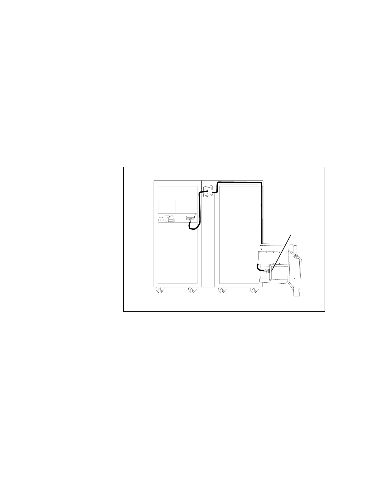
The T401 Tape Drive is factory–installed in one of the expansion cabinet
configurations shown earlier. The expansion cabinet is fitted with a special
external door extension frame to accommodate the auto loader(s) on the
Drive Assembly. An access door in the top of the extension frame opens
upward to allow insertion of a cartridge magazine in the autoloader. The
cabinet unpacking and installation procedures are the same as for any
Stratus universal cabinet. Follow the instructions in the Universal Cabinet
Announcement Bulletin (HA–002050) and the Stratus 40–Slot Systems
Installation and Operations Guide (HI–001030).
If the K122 IOA is located in a different expansion cabinet, route the SCSI
cable from the Formatter through the plenum using the procedure for
routing I/O cables found on page 12 in the Universal Cabinet
Announcement Bulletin.
K122
NOTE: Maximum SCSI cable length is 19 feet.
Installation
Routing the SCSI Cable
for the K122 IOA
7T401 Tape Drive Installation Instructions
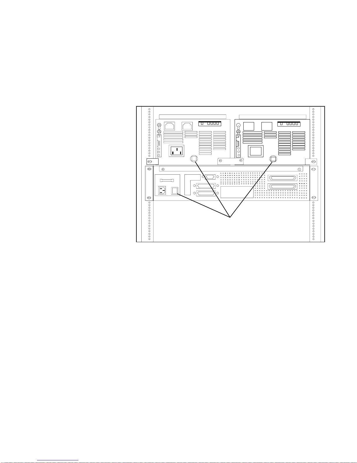
Perform the following procedure to make the T401 operational.
1. Install the K122 IOA card in its appropriate slot and connect the
SCSI cable.
2. Turn on the ac power switches on the rear of the Formatter and
Drive Assembly(s).
AC Power Switches
3. Load a magazine containing tape cartridges into the auto loader.
Making the Tape
Drive Operational

8T401 Tape Drive Installation Instructions
4. Turn on the dc power switch on the front of the Formatter to
initiate drive power sequencing and a series of self tests. Upon
successfulcompletionoftheselftests, thefrontpanelonthedrive
displays READY U. In a 1x2 configuration, one of the drives
(either one) displays the message READY U,and the other
displays the message IDLE.
Front Panel Display
Drive 1 Drive 0
Formatter DC Power Switch
5. Check that the devices.tinfile includes an entry for the tape drive
as shown in the example below.
name tape_1
module_name m1
device_type tape
terminal_type tape_drive_type_h
slot 4
adapter_slot_no 2
adapter_subchannel_no 7
For more information on configuring the K122 IOA and T401 tape drive,
refer to the Stratus Product Configuration Bulletin: K122 I/O Adapter and
T401 Tape Drive (R321).
Table of contents


