STRAXGAS Theme Plus User guide

Theme Plus Issue 2.1 28/06/01 Page 1 of 12
Appliance data:
Type of gas : Natural gas (G20) Cat. I2H Propane gas (G31) Cat. I3P
Injector size : 7 x 0.80 multihole 7 x 0.53 multihole
Injector marking : 80 53
Gross heat input (high setting) : 6.9kW (23,500Btu/h) 6.9kW (23,500Btu/h)
Gross heat input (low setting) : 4.4kW (15,000Btu/h) 3.5kW (12,000Btu/h)
Supply pressure : 20mbar (8in.w.g.) 37mbar (14.8in.w.g.)
Appliance test point pressure (cold) : 19.0mbar (± 1.0mbar) 36.5mbar
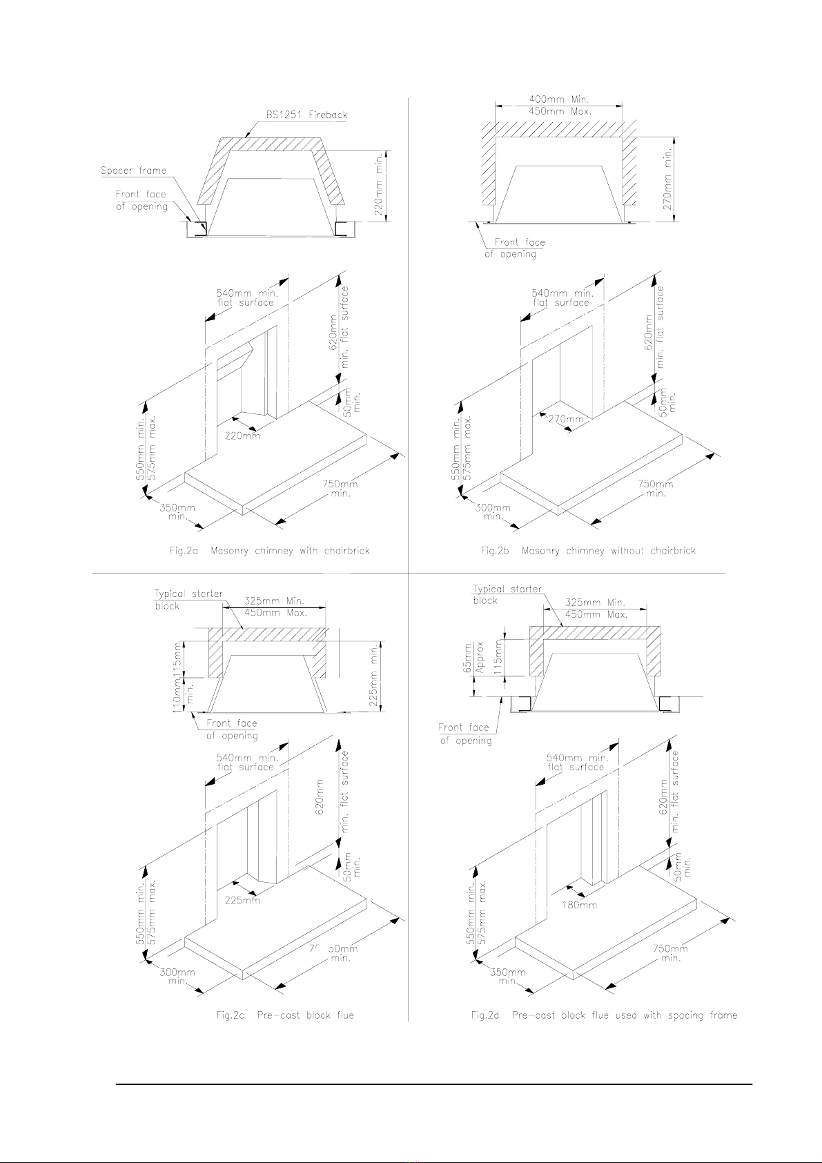
Type of flue : Class 1 (7in. dia.), Class 2 (5in. dia.) or precast block flue
Minimum effective height of chimney : 3m (10ft.) 3m (10ft.)
Ignition : Piezo Piezo
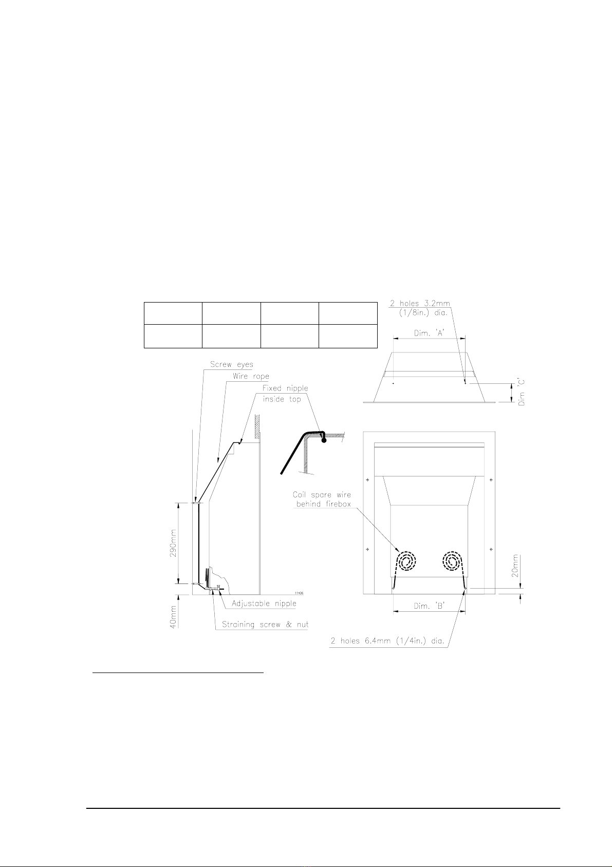
Spark gap : 3.0mm min., 4.5mm max. 3.0mm min., 4.5mm max.
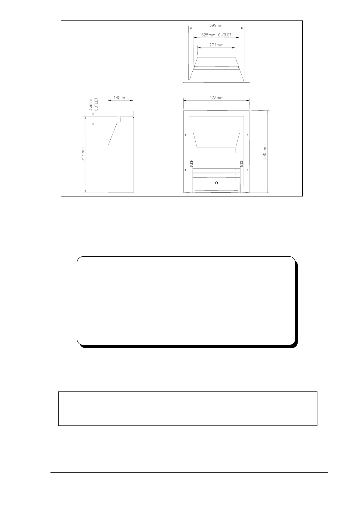
Dimensions:
Width over frame excluding trims : 473mm
Height including frame : 585mm (534mm Lowline Version)
Depth : 180mm
Shipping weight : 36kg
Country of destination : United Kingdom and The Republic of Ireland
NOTE: The Natural Gas and Propane Gas versions of this appliance are different models and
cannot be converted from one gas to another.
This appliance has been assessed by a Government appointed Notified Body and shown to meet the
'Essential Requirements' of the European Gas Appliance Directive.
The Directive lays down requirements for the safety of the appliance, together with its design,
construction, and use of materials. It also requires the production process to be covered by an
approved and monitored system of quality assurance.
Mandatory requirements
Straxgas fires must be installed with due regard to the following mandatory regulations:
The relevant British Standard installation specifications and codes of practice, and Building Regulations
issued by the Department of the Environment, and Building Standards (Scotland) Consolidated
Regulations issued by the Scottish Development Board.
Gas Safety (Installation and Use) Regulations.
Failure to install this appliance correctly could lead to prosecution and render the guarantee
invalid.
Attention is drawn to the latest edition of the following standards:
BS1251, Specifications of open-fireplace components.
BS5440, Part 1, Specification for installation of flues.
BS5440, Part 2, Specification for installation of ventilation for gas appliances.
BS5482, Part 2, LPG, installations in permanent dwellings.
BS5871, Part 2, Installation of decorative fuel effect gas appliances.
BS6891, Specification of low pressure gas pipework
BS8303, Replacing CP403.
This Straxgas appliance is an inset live fuel effect gas fire and must only be installed by a
competent person (e.g. a C.O.R.G.I. member) in accordance with these installation
instructions. This appliance must be installed in accordance with the rules in force, and used
only in a sufficiently ventilated space. Consult these instructions before installation and use of
this appliance.
Additional purpose made air ventilation is not normally required.
Ventilation must be provided in accordance with the rules in force.
INSTALLATION AND SERVICING INSTRUCTIONS FOR THE STRAXGAS
THEME PLUS WITH 16" ECOTECH BURNER
(To be left with the appliance)
Division of Legge Fabheat Ltd.
Longfield Road, Leamington Spa, Warks. CV31 1XB
Re
g
istered in En
g
land No 500091
IE & Northern Ireland
GB

Theme Plus Issue 2.1 28/06/01 Page 2 of 12
Preparation
Before installation
Ensure that the local distribution conditions (identification of the type of gas and pressure) and
the adjustment of the appliance are compatible. Refer to burner data badge plate.
All types of flue
Ensure that:
•It only serves one fireplace
•Any terminal or cowl fitted is approved for use with this type of appliance.
•It is clear of any obstruction and any damper or restrictor is removed or fixed
permanently in the fully open position.
•Any chimney used for an appliance burning a fuel other than gas must be thoroughly
swept before installing any gas appliances.
•With an L.P.G. (propane) fire, any air supply entering the fireplace below floor level is
completely sealed off.
•The chimney is properly sealed so that the combustion products do not come into
contact with combustible materials outside the chimney.
•The base of the chimney is clear of loose debris, bricking up, etc.
Check with a smoke match that there is a positive updraught present. If a terminal is fitted
check that it is free from obstruction and does not restrict the exit and safe dispersal of
combustion products.
Location
This appliance is not suitable for installation in a room containing a bath or shower.
The THEME PLUS may be installed to any of the following:
•A masonry chimney with a minimum cross sectional area of 24,000 sq.mm, lined flue
with a minimum dimension of 100mm or a minimum diameter of 175mm and a
minimum effective height of 3m and having a throat forming lintel conforming to
BS1251. The appliance may be installed either: (a) without removing the chairbrick
but the spacer frame MUST be used, (see Fig. 2a for minimum depth
requirements), or (b) in a builder's opening with sufficient volume for debris collection
conforming to Fig. 2b.
•A pre-cast block flue conforming to the requirements of BS1289 with a minimum
cross sectional area of 16,500 sq.mm and a minimum dimension of 90mm. The
appliance may be used with the spacing frame described above if it desired to fit a
shallow mantel. See Figs 2c and 2d for minimum depth requirements. Ensure that
mortar fangs between the blocks do not protrude into the flueway. It is essential that
the flue terminal does not restrict the flue flow and complies with BS1289; if not,
replace with an approved terminal.
•An insulated twin walled metal fluebox and flue system with a minimum diameter of
125mm, and minimum effective height of 3m. The system must conform to the
constructional requirements of BS715 and Fig. 4.
The different types of installation are fully described in the next section.
The appliance must only be installed into an opening against a non-combustible wall.
Clearances
If a shelf is to be fitted above the fire, perhaps as part of a surround, it must be positioned a
minimum of 1m (39in.) above the top of the hearth, and project no more than 200mm (8in.)
from the front plane of the opening. Combustible material such as wood may be fitted to within
100mm (4in.) of either side of the opening so long as it projects no more than 100mm (4in.)
from the front plane of the opening.
Soft furnishings, decorations and some wall coverings may discolour or scorch if positioned too
close to the fire

Theme Plus Issue 2.1 28/06/01 Page 3 of 12
Installing the fire
Site preparation
The Straxgas Theme Plus must be installed on a level, non-combustible hearth in accordance
with BS5871, Part 2. See also approved document J 1/2/3 "Heat Producing Appliances" issued
by the Department of the Environment.
Clear the working area of all debris before removing the Straxgas appliance from the
packaging.
Items supplied
The following items will be found within the carton:
1. Convection box.
2. Separate flat trim, optional canopy trim, or spacer frame with box trim depending on
options ordered.
3. Burner complete with controls
4. Restrictor plate, (use depends on type of installation).
5. Optional fret.
6. 1 back, 1 centre, & 2 front ceramic sections.
7. Coals (6 large, 4 small)
8. Foam sealing strip
9. Screws and wall plugs to complete the installation.
10. These installation instructions, guarantee card and end user operating instructions.
Warning: Only Straxgas approved ceramic blocks and coals, designed for this appliance,
must be used with this burner. Use of ceramic components from any other supplier will
invalidate the guarantee and may be dangerous.
When unpacking the appliance, avoid touching the visible, painted parts as the paint requires
curing (this will take approximately 2 hours under fire. In some cases there may be a slight
odour given off for a short period).
Fret options
The following Straxgas frets are suitable for use with this appliance:
•Black finger (brass or stainless finials &ash pan ring)
•Brass finger
•Stainless finger (polished or satin)
•Classic, Silver Classic
•Gainsborough (all brass or black)
•Delta (polished or satin)
If a fret from another manufacturer is being used, it must comply with the minimum free area
requirements shown in Fig. 1.
Gas connection
Note: Gas connection shall be with rigid or semi-rigid pipe, by concealed connection only. A
15mm (10mm for propane) gas supply pipe with isolation cock should be brought to within 1M
of the fireplace opening. The connection to the burner can be made from the right or left-hand
side by a concealed pipe from behind the burner to the elbow on the left-hand side of the
burner. Use a pre-punched hole in the convection box to allow the gas supply pipe to be
installed. 8mm pipe is required for this purpose.
When passing the pipe through brickwork or plaster, cap the end to prevent entry of debris.
Fig. 1 Optional fret min.
ventilation re
q
uirement
WARNING: Always blow pipework through before connecting to
appliance - contamination will permanently damage the burner.

Theme Plus Issue 2.1 28/06/01 Page 4 of 12
Lowline version
569mm
Lowline version
499mm Min
524mm Max
Lowline version
569mm
Lowline version
569mm
Lowline version
569mm
Lowline version
499mm Min
524mm Max
Lowline version
499mm Min
524mm Max
Lowline version
499mm Min
524mm Max
Lowline version
569mm

Theme Plus Issue 2.1 28/06/01 Page 5 of 12
Assembly sequence
Masonry chimney
With chairbrick (Fig. 2a)
1. Attach the spacer frame to the back of the convection box flange using the four
countersunk screws and nuts provided.
2. Fit the restrictor plate with its bottom edge inside the flue outlet, using 2 screws
provided, as shown in Fig. 3.
3. Secure the self-adhesive foam sealing strip to the back of the spacer frame (Fig. 3a).
4. Slide the firebox into position, making sure that the sealing strip is compressed and
forms an effective seal around the complete frame.
5. Drill the front face of the opening to match the 4 holes in the spacer frame and insert
the plugs provided.
6. Secure the convection box using the screws provided or alternatively use optional
wire fixing kit.
Without chairbrick (Fig. 2b)
1. Secure the self-adhesive foam sealing strip to the back of the convection box flange
(Fig. 3a)
2. Fit the restrictor plate with its bottom edge inside the flue outlet, using 2 screws
provided, as shown in Fig. 3.
3. Slide the convection box into position, making sure that the sealing strip is
compressed and forms an effective seal around the complete frame.
4. Drill the front face of the opening to match the four holes in the flange of the
appliance and insert the plugs provided.
5. Secure the convection box using the screws provided or alternatively use optional
wire fixing kit.
Pre-cast block flue (Figs. 2c and 2d)
Note: The outlet restrictor plate must not be used with this installation.
1. If the spacer frame is being used, attach it to the back of the convection box flange
using the four countersunk screws and nuts provided.
2. Secure the self-adhesive foam sealing strip to the back of the spacing frame or
convection box flange as appropriate (Fig. 3a).
3. Slide the convection box into position, making sure that the sealing strip is
compressed and forms an effective seal around the complete frame.
4. Drill the front face of the opening to match the four holes in the flange of the
appliance and insert the plugs provided.
5. Secure the convection box using the screws provided or alternatively use optional
wire fixing kit.
Wire Fixing Kit (Optional)
The kit supplied enables the convection box to be secured to
the opening without drilling any holes in the surround.
Items supplied:
1. 2 wire ropes with fixed nipple
2. 2 Sleeve bolts and backnuts
3. 2 Adjustable nipples with clamp screws
4. 4 Screweyes and wall plugs
1. Mark out and drill 4 holes in the back of the opening to
suit wall plugs supplied. See the drawing for
dimensions. Insert the screweyes and align to allow the
wires to pass through vertically.

Theme Plus Issue 2.1 28/06/01 Page 6 of 12
2. If the convector box has not been pre-punched for the wire ropes, drill the top and
back shown in the drawing, removing burrs from the drilled holes.
3. Pass one wire rope through each top hole, from the inside out, and pull through until
the fixed nipple rests against the inside of the top plate.
4. Place the convector box near the opening and pass each wire rope through the top
and bottom screweyes, and back through the holes in the back of the convector box.
5. Push the convector box into the opening up to the surround, pulling the wire ropes
through to take up all slack.
6. Run the backnuts up to the heads of the sleeve bolts, and thread a sleeve bolt over
each wire rope, threaded end first.
7. Push the sleeve bolts into the holes in the back of the convector box as far as the
backnuts.
8. Thread an adjustable nipple on to each wire rope up to the heads of the sleeve bolts.
Pull any slack wire through the nipple and tighten the clamp screws.
9. Make sure that the foam seal behind the fire flange is compressed all round and
then, using two spanners, screw the backnuts down the sleeve bolts in order to
tension the wire ropes and hold the convector box against the surround.
10. Coil up surplus wire rope and store inside convection channel (see drawing). Do not
cut off surplus; possible future removal and refitting of convector box requires the
full length of wire supplied.
Metal fluebox and flue system (Fig. 4)
Note: The outlet restrictor plate must not be used with this installation.
1. The metal fluebox must stand on a non-combustible hearth of at least 50mm
thickness.
2. The top, sides and rear of the box must be covered with a 50mm minimum thickness
of mineral wool insulation.
3. Secure the self-adhesive foam sealing strip to the back of the convection box flange.
4. Slide the convection box into position, making sure that the sealing strip is
compressed and forms an effective seal around the complete frame.
5. Drill the front face of the opening to match the 4 holes in the flange of the appliance
and insert the plugs provided.
6. Secure the convection box using the screws provided.
Fire type Dim. ‘A’ Dim. ‘B’ Dim. ‘C’
Theme
Plus 16”
260mm 250mm 65mm

Theme Plus Issue 2.1 28/06/01 Page 7 of 12
Fi
g
. 8 The data bad
g
e plate & test
Final assembly for all types of flue
Following satisfactory installation of the convection box into the opening, proceed as follows:
1. Secure the burner to the convection box using the two screws provided, through the
holes in the front of the legs.
2. Connect the gas supply pipe to the inlet elbow.
3. The ceramic components are fragile and should be handled with care. Refer to Figs.
5 and 6 for positioning of ceramic fibre blocks and coals.
4. Place the chair shaped back ceramic on the burner, pushing it back against the
upturned edge of the burner plate.
5. Place the centre ceramic on the back ceramic pushing it back to sit comfortably
between the tapered sides.
6. Spring forward the slotted front plate and slide the front ceramics down as far as the
stops.
7. Remove the coals from the bag; note that there are 2 sizes supplied with the burner.
Place them on the ceramic blocks in accordance with Fig. 6.
8. If a flat trim or box trim has been supplied, attach it to the fire flange by means of the
magnets. If the optional canopy trim has been supplied, first remove and discard the
existing front cover by undoing the two screws in its bottom edge, then secure the
canopy trim using the same fixings. (See Fig. 7)
Note: The flat trim and optional canopy trim cannot be used with the spacer frame.
Leak test & pressure test
1. Turn on the main gas supply and check for gas soundness.
2. Remove pressure test screw, and fit pressure gauge to pressure test point.
3. Light the fire (see next section).
4. Turn control knob anti-clockwise to High position.
5. When the control knob is in the High position, you should have a gas pressure of
19.0mbar ± 1.0mbar when using natural gas and 36.5mbar for propane.
6. Extinguish the fire by turning the control knob clockwise to the Off position.
7. Remove the pressure gauge and replace the pressure test screw. Check again for
gas soundness.
8. Fit the front fret by hooking the support lugs at each end over the slotted front plate
on the burner (if using a Straxgas fret), or place an alternative front fret in front of the
burner.
Note: If a fret from another manufacturer is being used, it must comply with the minimum free
area requirements of Fig. 1.
Fig.6 Placing the loose coals
Back ceramic
Centre ceramic
Front ceramic
Fig.5 Assembling the ceramic blocks
Fig.9 Data badge plate - propane version

Theme Plus Issue 2.1 28/06/01 Page 8 of 12
Lighting the fire
The appliance Data Badge is positioned in front of the burner behind the fret and carries the
control knob positions (Fig. 8 or 9 depending on gas type). The full lighting procedure is as
follows:
1. Push control knob in as far as possible on gas control.
2. Turn knob anti-clockwise until a click is heard. The knob will stop at the ignition
position and a spark should be seen at the tip of the ignition probe. At the same time
the pilot flame should light. KEEP THE KNOB PRESSED IN FOR 10 SECONDS. If
the pilot should fail to light, turn the control knob clockwise to the 'off' position, wait 3
minutes and repeat the procedure.
3. When the pilot flame is alight the control knob should be allowed to spring out
slightly. Turn the knob fully anti-clockwise to the high position. The pilot flame
should then ignite the main fire.
4. The height of the flames can be adjusted by turning the control knob between the low
and high positions. Note that the knob 'latches' in position at either end of this
movement and must be pushed in slightly before it can be turned.
5. The appearance of the flames can be altered by means of the air adjustment lever
positioned to the right of the control knob (natural gas version only). Moving the lever
up will admit more air and produce a 'coke fire' effect. Moving it down will close off
some of the air and simulate a 'coal fire' with flickering flames.
6. To turn the fire off, depress the knob slightly and turn it to the pilot position.
7. To completely extinguish the fire depress the knob slightly and turn to the 'Off'
position.
Check for clearance of products of combustion
1. Light the fire.
2. Close all windows and doors.
3. After approximately 5 minutes place a smoke match 70mm from the right hand side,
inside edge of the trim, 10mm below and 10mm within the opening of the fire as
shown in Fig. 10, 10a, & 10b. Ensure that the smoke is drawn into the fire aperture. If
spillage is detected, operate the fire for a further 10 minutes and repeat the test. If
spillage is still detected introduce ventilation into the room by opening a window or
door. If spillage is no longer detected then purpose made ventilation with a minimum
area of 100 sq.cm must be provided. If after introducing ventilation into the room
spillage is still detected, remove the restrictor plate if fitted (see Fig. 3) and retest for
spillage. If spillage is still detected the cause must be discovered and the fault
corrected. If the fault cannot be corrected, disconnect the gas supply to the appliance
and seek expert advice. Possible causes of spillage are chimney restrictions, or an
incorrect cowl or terminal.
4. If there is an extraction fan in a nearby room then the spillage test must be repeated
with the fan turned on and any interconnecting doors between the fire and the fan
location left open.

Theme Plus Issue 2.1 28/06/01 Page 9 of 12
Instruct the user
1. Hand over these Installation Instructions and the User Instructions to the person who
is going to use the fire and explain how to light and operate the appliance. Explain
how the fire may be lit, if necessary, by means of a long spill or taper.
2. Make certain that the user is aware that the ceramic blocks and coals must be
located in accordance with the instructions, and that the appliance should be
serviced at regular intervals by a competent person to ensure continued safe
operation.
3. Explain that this appliance is fitted with an oxygen depletion sensor incorporated into
the pilot body. Should the fire repeatedly extinguish itself, the cause should be
sought and remedied as this may indicate spillage into the room of combustion
products.
4. Indicate the tie-on warning label, which the customer must remove and read.
5. Advise the user that any smell given off by the appliance will clear away after a little
use.
6. Point out that these instructions must be retained in a safe place for future use.
Maintenance
Servicing should be carried out regularly by a competent person in accordance with these
instructions and the relevant regulations, to ensure the safe and correct operation of the
appliance.
At least once a year check for debris in the flueway. If soot has accumulated ensure that the
chimney is swept clean.
Before commencing any service or replacement of parts, turn off the main gas supply and
ensure that the fire is cold.
When ordering spare parts please quote appliance serial number which can be found on the
data badge plate.
Ceramics
Examine the coals and ceramic blocks for signs of cracking and replace if necessary. Handle
the ceramic components with care. Dust off any soot or deposits with a soft brush. Do not
vacuum clean.
Removal of burner & convection box
1. Turn off the gas supply by the isolation cock.
2. Disconnect the 8mm pipe from the elbow at the left-hand side of the burner.
3. Remove the flat trim, box trim, or optional canopy trim.
4. Remove the 2 screws holding the burner to the convection box and lift the burner out
of the opening.
5. Remove the 4 screws in the flange of the convection box, and lift the box out of the
opening.
6. Examine the flue for debris and clean if necessary.
7. Reassemble in the reverse order.
8. After servicing check for gas soundness.
Following a service, a check should be made for clearance of combustion products. Follow the
procedure detailed in these instructions.
Cleaning the fire
Black paint: Use only a clean damp cloth. Do not use any cleaning agents.
Brass parts: Use Brasso or Duraglit ensuring that it does not come into contact with the black
paint finish.
IMPORTANT - The paint finish is durable and heat resistant, however it will be damaged if
plaster, cement or wallpaper paste is allowed to come into contact with it. Protect the
appliance during re-building or decorating work.

Theme Plus Issue 2.1 28/06/01 Page 10 of 12
Replacement of parts
Before commencing any servicing always ensure that the fire is isolated from the gas supply
and that the fire is cold. After servicing always check for gas soundness.
Replacement of gas tap/FSD/piezo igniter
1. Turn off the gas supply by isolation cock.
2. Lift off the front fret and remove the coals and ceramic blocks.
3. Remove 2 screws holding burner to box.
4. Undo multidirectional gas connection.
5. Remove burner from the appliance.
6. Pull off control knob.
7. Remove the 2 screws securing the Data Badge plate and remove the plate.
8. Disconnect ignition lead to the igniter unit.
9. Disconnect all 3 gas connections to gas valve as well as the connection to the
thermocouple.
10. Remove 2 screws securing the valve to the mounting bracket, and discard old
tap/FSD/piezo igniter complete.
11. Assemble the new tap/FSD/piezo igniter on the mounting bracket. Ensure that the
filter is in position in the pilot outlet orifice on the tap body.
12. Reassemble the appliance in reverse order.
13. Replace the ceramic blocks and coals (see Figs. 5 and 6).
14. Turn on the gas supply and check for soundness.
Note: The igniter is not replaceable separately.
Replacement of main injector
1. Repeat operations 1 - 5, as described for 'Replacement of gas tap/FSD/piezo igniter'.
2. Remove gas pipe from gas valve to injector.
3. Unscrew injector and replace, making certain that the jet size stamping corresponds
to the specification on the Data Badge plate.
4. Reassemble in reverse order.
5. Turn on the gas supply and check for soundness.
Replacement of ignition & pilot assembly
1. Repeat operations 1 - 7, as described for 'Replacement of gas tap/FSD/piezo igniter'.
2. Disconnect thermocouple connection to the gas tap/FSD/piezo igniter.
3. Disconnect pipe from base of pilot burner tube.
4. Pull off connector on the base of the igniter probe.
5. Remove 2 screws on gas burner and remove ignition unit complete.
6. Fit new pilot assembly and reassemble in reverse order.
7. Turn on the gas supply and check for soundness.
8. Check operation of ignition system.
Fig. 11 Underside of burner

Theme Plus Issue 2.1 28/06/01 Page 11 of 12
NOTE: No liability can be accepted unless this product has been installed and operated
strictly in accordance with these manufacturer's instructions
U.K. Registered Design 2040268. British Patent Application 9414887.1
Design right reserved © Legge Fabheat Ltd.
SPARE PARTS
When ordering spare parts please quote part numbers as listed below:
NATURAL GAS L.P.G. (Propane)
Gas tap / FSD / piezo igniter BV50023 BV50147
Oxypilot assembly BA50004 BA50041
Injector BI70800 BI70530
Back ceramic BC11300 BC11300
Centre ceramic BC11296 BC11296
Front ceramic - set of 2 BC11295 BC11295
Set of 10 loose coals BC50032 BC50032
Fig. 12 Theme Plus outline drawing without trim
Lowline Version
534mm
Lowline Version
494mm

Theme Plus Issue 2.1 28/06/01 Page 12 of 12
Lowline Version 565mm
Lowline Version 545mm
Lowline Version 565mm
Lowline Version 579mm
Lowline Version 495mm
Other manuals for Theme Plus
1
This manual suits for next models
1
Table of contents
Other STRAXGAS Indoor Fireplace manuals
Popular Indoor Fireplace manuals by other brands

Napoleon
Napoleon bL36 quick start guide

MASTERFLAME
MASTERFLAME TED25 G3 Homeowner's manual

FMI
FMI Masonry MM33 instructions

Greentouch
Greentouch kathy ireland HOME 1591FSO-28-247 Assembly / care & use instructions

Riello
Riello 40 Series Installation, use and maintenance instructions

Dimplex
Dimplex DF2690 Service manual

Enviro
Enviro Cara owner's manual

Napoleon
Napoleon NFI-D Deluxe installation instructions

Century
Century CW2100-I owner's manual

IN & OUT HOUSE
IN & OUT HOUSE EM279B instruction manual

Archgard
Archgard Pele 345 Series Installation, operation and maintenance manual

Kemlan
Kemlan 700 Low Line installation instructions