Pro-face PL-5700 Series User manual

1
PL-5700 Series User’s Manual
Preface
Digital’s PL-5700 series of Panel Computers (hereafter referred to as the “PL”) are
multipurpose factory automation (FA) computers, which embody Digital’s latest,
cost-effective architecture.
Before using the PL, be sure to read this manual thoroughly to familiarize yourself
with the PL’s operation procedures and functions.
The word “PL” refers to the following models:
PL-5700T1-24VC (with CE marking)
PL-5700T1 (Standard 100V unit)
PL-5701T1 (Standard 100V unit)
PL-5700S1 (Standard 100V unit)
PL-5701S1 (Standard 100V unit)
PL-5700L1 (Standard 100V unit)
PL-5701L1 (Standard 100V unit)
1. It is forbidden to copy the contents of this manual in whole, or in part, without the
permission of the Digital Electronics Corporation.
2. The information in this manual is subject to change without notice.
3. This manual was written with care; however, if you should find any error or omis-
sions, please contact Digital and inform them of your findings.
4. Please be aware that Digital is not responsible for damages resulting from the use
of our products, regardless of article 3.
5. Specifications set out in this manual are for overseas products only,and,as a
result,some differences may exist between the specifications given here and the
Japanese ones.
Product names used in this manual are the trademarks of their respective manufac-
turers.
© Copyright 1997, Digital Electronics Corporation
MS-DOS®and Windows®are registered trademarks of the Microsoft Corporation.
IBM®DOS®are registered trademarks of IBM.
NOTE:
2PL-5700 Series User’s Manual
Preface
Safe Product Usage
This manual contains a variety of safety markings to help you safely and correctly
operate Digital’s PL-5700 series of Panel Computers, which includes the PL-5700T1,
PL-5701T1, PL-5700L1, PL-5701L1, PL-5700S1, PL-5701S1, and PL-5700T1-
24VC. Be sure to keep this manual handy for future reference.
Safety Icons
This manual uses the two icons below to call attention to information important for the
safe and correct use of the PL. Please pay attention to these icons and follow all
instructions given by them.
The safety icons and their meanings are:
Indicates a potentially hazardous situation which could result in
serious injury or even death, if the instructions are not followed.
Indicates a potentially hazardous situation which could result in
minor injury or equipment damage if the instructions are not fol-
lowed.
Essential Safety Precautions
Be sure to follow the instructions given below to ensure the safe use of the PL.
To avoid a possiblity of electrical shock, be sure to connect
the power cord to the PL before connecting it to the main
power supply.
To avoid fires or electrical shocks, do not use voltages be-
yond the specified range.
Before opening the PL’s protective cover, be sure to turn the
unit’s power OFF. This is because the PL’s internal parts
carry high voltages.
To avoid fires or electrical hazards, do not modify the prod-
uct in any way.

3
PL-5700 Series User’s Manual
Preface
Before replacing the 100V unit’s backlight, be sure to turn
the unit’s power OFF to avoid electrical shocks. (Note: Do
NOT attempt to replace the 24V unit’s backlight)
Do not create touch panel switches that are used to either
control or to ensure the safety of equipment and personnel.
Mechanical switches, such as an emergency stop switch, a
deadman (two-handed) start switch, etc., must be installed
and operated via a separate system.
If metal particles, water or other types of liquids contact any
of the PL’s internal parts, immediately turn the unit’s power
OFF, unplug the power cord, and contact either your dealer
or Digital Electronics Corporation.
Read and understand Chapter 4 “Installation and Wiring”
thoroughly in order to select an appropriate installation loca-
tion for the PL.
Before either plugging in or unplugging a board or interface
connector, be sure to turn the PL’s power OFF.
To prevent a possible explosion, do not install the PL in ar-
eas containing flammable gases.
General Safety Precautions
Follow the instructions given below for correct and safe use of the PL.
• Do not push on the PL’s screen too strongly, with either your
finger or with a hard object. Excessive pressure can
scratch, crack or damage the screen.
•If the screen becomes dirty or smudged, moisten a soft cloth
with diluted neutral detergent, wring the cloth well, and wipe
the display. Do not use thinner or organic solvents.
• Do not use a pointed object, such as a mechanical pencil or
screwdriver, to press any of the touch panel’s switches,
since they can damage the display.
• Avoid exposing and operating the PL in direct sunlight, high
temperatures and humidity, and in areas where excessive
dust and vibration will occur.

4PL-5700 Series User’s Manual
Preface
• To prevent the PL from overheating, be sure its air circula-
tion vents are clear and clean, and keep the unit’s operation
area well-ventilated.
• Avoid operating or storing the PL near chemicals, or where
chemicals can come into contact with the unit.
• Before the PL is initially started, be sure to install its memory
(DIM) module. If this module is not installed, the unit will not
operate.
Notes on Handling the LCD
The FP's LCD contains a strong irritant. If the panel is ever cracked and the LCD's
liquid contacts your skin, be sure to wash it with running water for at least 15
minutes. If any of this liquid should enter your eye, be sure to flush your eye with
running water for more than 15 minutes, and see a doctor immediately.
The current brightness of the LCD screen will depend on the screen's current dis-
play and the LCD's contrast adjustment. Any brightness variations that result are
normal for LCD displays (i.e. dark and light points).
There are minute grid-points on the LCD surface. These points are not defects.
Occasionally crosstalk (shadows appearing on extended display lines) will appear
on the display. This phenomenon is a common attribute of LCDs and is not a
defect.
The displayed color will look different when viewed from an angle outside the
specified view angle. This is also normal.
Displaying a single screen image for long periods of time can cause an afterimage to
remain on the screen. To correct this, turn the unit OFF for 5 to 10 minutes, then
ON again. This phenomenon is a common attribute of the LCDs, and is not a
defect. To prevent this effect, you can:
- use the Display OFF feature; if the same image is to be displayed for a long
period of time.
- change the screen display periodically to prevent the displaying of a single
image for a long period of time.

5
Series PL-5700 User’s Manual
Table of Contents
Preface Preface ......................................................................................................... 1
Safe Product Usage...................................................................................... 2
Safety Precautions ....................................................................................... 2
Table of Contents......................................................................................... 5
Before Using the PL .................................................................................... 8
Features........................................................................................................ 9
Unpacking the PL ........................................................................................ 10
Information Symbols ................................................................................... 10
Chapter 1 Overview
1-1 System Configuration..................................................................................... 1-1
1-2 Options ........................................................................................................... 1-2
1-3 PL Series Panel Types .................................................................................... 1-3
Chapter 2 Specifications
2-1 General Specifications................................................................................. 2-1
1. Electrical Specifications .............................................................................. 2-1
2. Environment Specifications......................................................................... 2-1
3. Dimensions .................................................................................................. 2-2
2-2 Performance Specifications ......................................................................... 2-3
1. Performance Specifications ......................................................................... 2-3
2. Display Functions ........................................................................................ 2-4
3. Expansion Slots ........................................................................................... 2-6
2-3 Interface Specifications ............................................................................... 2-7
1. Printer Interface ........................................................................................... 2-7
2. Keyboard Interface ...................................................................................... 2-7
3. Mouse Interface ........................................................................................... 2-7
4. RS-232C Interface (COM1/COM2) ............................................................ 2-8
5. RS-485 Interface (COM3) ........................................................................... 2-8
6. Jumper Settings ........................................................................................... 2-9
7. Using the Contrast Adjustment Knob ............................................................ 2-10
2-4 PL External Features ................................................................................... 2-11
2-5 PL Dimensions ............................................................................................ 2-13
1. PL-5700T1 PL-5700T1-24VC, PL-5700S1, PL-5700L1 : ..................................
General Dimensions ....................................................................................... 2-13
2. PL-5701T1, PL-5701S1, PL-5701L1 : General Dimensions................................ 2-14
3. Installation Hole Dimensions ...................................................................... 2-15

6PL-5700 Series User’s Manual
Chapter 3 Installing Optional Units and Expansion Boards
3-1 Available Options and Expansion Boards................................................. 3-1
3-2 Installing Options and Expansion Boards................................................. 3-3
1. Installing DIM Modules (PL-EM000/EM001/EM002).......................... 3-3
2. Installing the External Cache Memory Board (PL-EC000).................... 3-5
3. Installing the HDD unit (PL-HD000) or the Flash File Disk Unit (PL-FF000/FF001) .. 3-6
4. Installing the FDD Unit (PL-FD000/FD001) ......................................... 3-10
5. Installing the Memory Card Interface Unit (PL-MC000)....................... 3-13
6. Installing the IDE Slave Adapter (PL-SA000) ....................................... 3-14
7. Installing the Flash ROM Board (PL-FR000) ........................................ 3-15
8. Installing an Expansion Board................................................................ 3-16
Chapter 4 Installation and Wiring
4-1 Installing the PL ........................................................................................ 4-1
1. Installation Procedures ........................................................................... 4-1
4-2 Wiring the PL ............................................................................................ 4-5
1. Connecting the Power Cord.................................................................... 4-5
2. Cautions: 100V PL-5700 T*/S*/L* Units .............................................. 4-7
3. Grounding Cautions................................................................................ 4-8
4. Cautions When Connecting I/O Signal Lines......................................... 4-8
Chapter 5 System Set-up
5-1. Set-up Procedures .................................................................................... 5-1
5-2. System Parameters ................................................................................... 5-3
1. Main........................................................................................................ 5-3
2. Advanced................................................................................................ 5-6
3. Power...................................................................................................... 5-8
4. Exit ......................................................................................................... 5-9
Chapter 6 Bundled Software
6-1 File List ..................................................................................................... 6-1
6-2 Touch Panel Input File .............................................................................. 6-3
1. PLATPH.EXE (Touch Panel Handler) ................................................... 6-3
2. PLCALIB.EXE (Touch Panel Data Calibration) .................................... 6-11
6-3 Other Files................................................................................................. 6-13
1. DISP.EXE (Display ON/OFF Program) ................................................. 6-13
2. FANALARM.EXE (CPU Cooling Fan Alarm Detection Program)....... 6-13
3. BLSAVER.SCR (Windows®3.1 Screen Saver / Windows®95 Screen Saver) .... 6-13

7
Series PL-5700 User’s Manual
Chapter 7 Maintenance and Inspection
7-1 Cleaning the Display................................................................................. 7-1
7-2 Replacing the 100V Unit’s Backlight ....................................................... 7-2
7-3 Periodic Check .......................................................................................... 7-3
Appendices
1. Hardware Configuration .............................................................................. A-1
1. I/O Mapping....................................................................................... A-1
2. Memory Mapping .............................................................................. A-3
3. IRQ Mapping ..................................................................................... A-4
2. Serial Communications ............................................................................... A-5
3. Printer Cable Connections ........................................................................... A-6
4. Touch Panel Handler Sample Program........................................................ A-7
5. BIOS Lists ................................................................................................... A-15
Index..................................................................................................................... i - iii
8PL-5700 Series User’s Manual
Before Using the PL
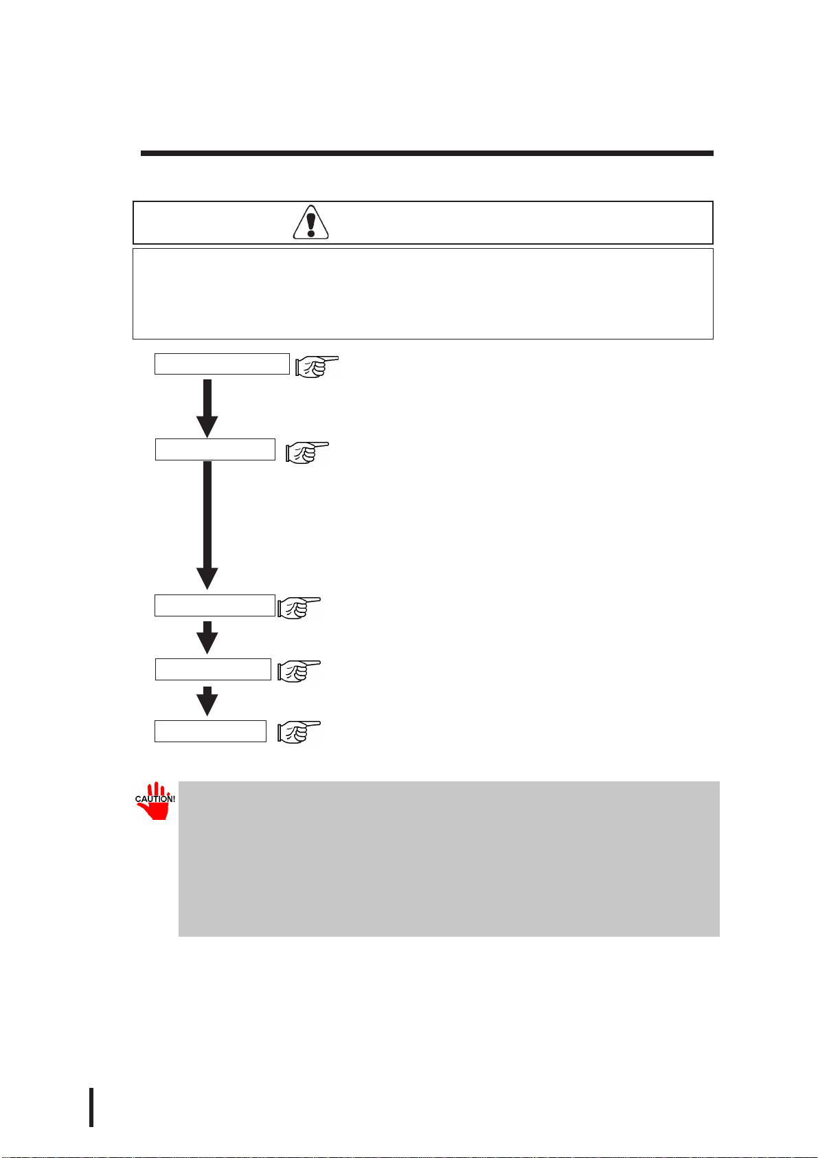
Prior to use, be sure your PL is set up as follows.
Install PL memory Refer to 1-2 Options and the instruction manual that came
with the memory; 3-2 1. Installing the DIM Module (PL-
EM000/EM001/EM002); 3-2 2. Installing the External
Cache Memory Board (PL-EC000)
Install HDD unit Refer to 1-2 Options and the instruction manual that came
with either the HDD unit; 3-2 3. Installing the HDD Unit
(PL-HD000),or the FlashFileDiskUnit (PL-FF000/FF001);
3-2 4. Installing the FDD Unit (PL-FD000/FD001); 3-2 5.
InstallingtheMemoryCardInterfaceUnit(PL-MC000)”;
3-2 6. Installing the IDE Slave Adapter (PL-SA000); 3-2
7. Installing the Flash ROM Board (PL-FR000)
Turn the PL ON Refer to 4-2 Wiring the PL
System Setup Refer to Chapter 5 System Set-up
OS Installation Refer to the OS’s installation manual (e.g. Windows®95
package’s manual)
• For system setup and OS installation, a PS/2 type keyboard is necessary.
• To use Windows®3.1 or Windows®95, install the PL-5700 Driver & Utility
Disk’s Display Driver. (For installation information, see the disk’s
README.TXT file)
• For information on the PL-5700’s bundled utility software, see the
README.TXT file on the Driver & Utility Disk.
Caution
• Before turning the PL ON, be sure to install its memory
(DIM module). If this module is not installed, the PL can be
turned on, but will not operate.

9
Series PL-5700 User’s Manual
Special Features
The main features of PL series displays are as follows:
The Latest, High-Performance Architecture
Designed around the AMD 5x86 133 MHz CPU, the PL utilizes the type of high
performance architecture used by most PC compatibles.
Bright 10.4" LCD with a Wide Viewing Angle
The PL’s large 10.4-inch 640 ´ 480 LCD display is available with TFT or STN
color, as well as monochrome, each offering excellent visibility and brightness.
•Digital’s top of the line TFT color LCD model allows you to create detailed
and powerful visual images, with excellent brightness, a wide viewing angle,
and a display capable of 260,000 colors.
•In addition to their superior cost performance, Digital’s STN type LCDs pro-
vide a high quality color display at a reasonable price.
•The black-and-white LCD models are high-performance, low-cost displays,
equipped with a virtually maintenance-free backlight. This long lasting light
has a service life of 45,000 hours.
Easy Front Panel Installation
The PL is designed to be installed easily into the front of any panel or device. It is
also rugged enough for use in harsh, industrial environments, such as those found
in the factory automation industries.
High Resolution, Analog-Resistance-Film Touch Panel
Standard equipment with the PL is a high resolution 1024 x 1024 touch panel.
Also, the bundled Windows®95 keyboard emulation utilities and MS-DOS®
touch-panel handler allow you to operate a variety of software applications with-
out ever having to connect a keyboard. An optional Windows®95 mouse emula-
tion utility is also available.
Highly Expandable
For the easy enhancement of your PL unit, ISA-bus expansion slots are provided.
The PL-5700T1, PL-5700T1-24VC, PL-5700S1, and PL-5700L1 each provide
three ISA-bus expansion slots, and the PL-5701T1, PL-5701S1, and PL-5701L1
each provide one. These slots can accommodate both Digital’s own optional
boards as well as other commercially available expansion boards. Digital also
offers a wide variety of optional products, such as an HDD unit, an FDD unit, and
an external cache memory board.

10 PL-5700 Series User’s Manual
Information Symbols
This manual uses the following icons.
Indicates a warning or a product limitation. Be sure to follow the instruc-
tions given with this icon to insure the safe operation of the PL.
Contains additional or useful information.
*Indicates terms or items that require further explanation. See the footnote
on that page.
Indicates pages containing related information.
1. 2. Indicates steps used to accomplish a given task. Be sure to follow these
steps in the order they are written.
Unpacking the PL
The PL package should include the following items:
When using the function keys,
attach the labels as shown below.
PL-5700
User’s
Manual
PL Unit
PL-5700T1, PL-5700T1-24VC
PL-5701T1, PL-5700S1, PL-5701S1,
PL-5700L1, PL-5701L1
Installation Gasket
Power Cord (not
included with 24V model)
Function Key Labels
Mounting Brackets
(four)
Driver & Utility Disk
Panel Computer
PL-5700 Series
User’s Manual
PL-5700 Series User’s Manual 1-1
1-1 System Configuration
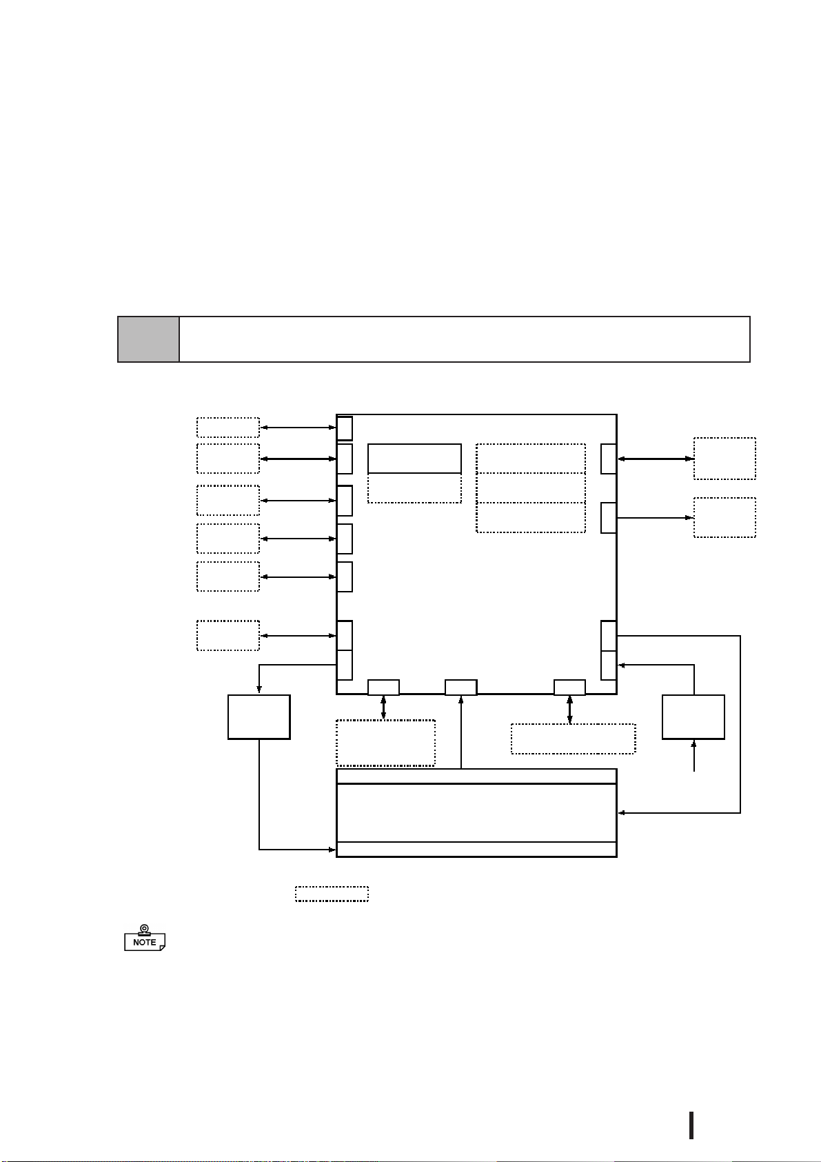
The following figure shows the peripheral devices that can be connected to the PL.
The figure above shows simply the internal data flow and the PL’s peripheral connec-
tions, and may differ from the actual layout used by the customer.
1-1 System Configuration
1-2 Options
1-3 PL Series List
* Devices in dotted boxes are Digital optional products or commercially available products.
Main board
Peripheral
device
Peripheral
device
Printer
RS-232C I/F
RS-485 I/F
Printer I/F
12 VDC output
Inverter
power
supply FDD unit/memory
card I/F unit
FD I/F
Analog resistance film touch panel
Display
LCD panel
(TFT color LCD, STN color LCD, or black-and-white LCD)
Backlight
Touch panel I/
FEXT-ISA I/F
Expanded mother
board (PC/AT type)
COM2
COM3
LPT1
5/12 V DC input
Power
supply
100 V AC
or 24V DC
Keyboard
Peripheral
device
PS/2 I/F
RS-232C I/F
CPU AM5x86
133MHz
HDD unit
COM1
DIM module
External cache
memory board
Flash ROM
board
CD-ROM
Hard disk
CD-ROM
power
supply
5/12 VDC
output
EXT-IDE I/
F
LCD I/F
Mouse
PS/2 I/F
Chapter
1Overview

PL-5700 Series User’s Manual
Overview
1-2
1-2 Options
The following table provides a list of optional products for the PL.
Expansion Options
Accessories
Maintenance Options
Software Options
Name Model
number Description
DIM module PL-EM000
PL-EM001
PL-EM002
Main memory module
(PL-EM000: 4MB, PL-EM001: 8MB, PL-EM002: 16MB)
Externalcache
memory board PL-EC000 256-KBsecondary cache board
HDD unit PL-HD000 Dedicated HDDunit with built-in 2.5"540 MB hard disk
FDD unit PL-FD001 PC/AT compatible 3.5"FDDunit
PL-FD000 PC/AT compatible 3.5" FDD unit for development and
maintenance
Memory card
interface unit PL-MC000 JEIDA-compliant(Ver. 4.1)IC memorycard interface
(Cannot write to flash-memory type cards)
IDE slave
adapter PL-SA000 Adapter for attaching IDE (ATAP I)-compliant CD-R OM drive
(DC powercord included)
Flash file disk
unit PL-FF000 3-MB silicon disk unitcompatible with hard disks
PL-FF001 10-MB silicon diskunit compatible with hard disks
FlashROM
board PL-FR000
FlashROMboard whichaccommodates up to two 2-MB ROM
drives. One drive can be assigned to drive A: or B: (the OS
starts from drive A: only). The other drive can be assigned to
drive C: orlater. Eachdisk canbe separatelyprogrammed.
(FR OMDISK Programming Tool included.)
Name Model number Description
Screen
protection sheet PL-CS001 Disposable overlay sheets for display protection and stain
resistance. Touchpanelswitches willstillsense yourtouchwhe
n
the sheetis inplace.
Name Model number Description
Backlight GP570-BL00-MS Replacement backlight available for TFT and STN colo
r
LCDs.
Mounting
brackets GP070-AT00-MS Hardware for installing the PL. Same as PL's origina
l
brackets.
Moisture
resistant
packing GP570-WP00-MS Moisture resistant packing used when installing the PL
.
Same asPL's originalpacking.
TT-WIN for Windows
®
3.1 Mouse emulation utilities for the touchpanel's screen
TT-WIN forWindows
®
95

PL-5700 Series User’s Manual
Overview
1-3
^ ^ ^
* if “24VC” is not
written, the unit is
100V type.
Expansion Slots
Display
B/W LCD PL-5701L1 PL-5700L1
STN color LCD PL-5701S1 PL-5700S1
TFT color LCD PL-5701T1 PL-5700T1/
PL5700T1-24VC
1-Slot type 3-Slot Type
1-3 PL Series Panel Types
Model number
P L - 5 7 0 0 T 1-24VC*
PL-5700 series Display type
Expansion slots L : Black-and-white LCD
0 : 3-slot type S : STN color LCD
1 : 1-slot type T : TFT color LCD

PL-5700 Series User’s Manual 1-4
MEMO
This page is intentionally left blank.

2-1
Panel Computer PL-5700 Series User’s Manual
Chapter
2Specifications
2-1 General Specifications
2-2 Performance Specifications
2-3 Interface Specifications
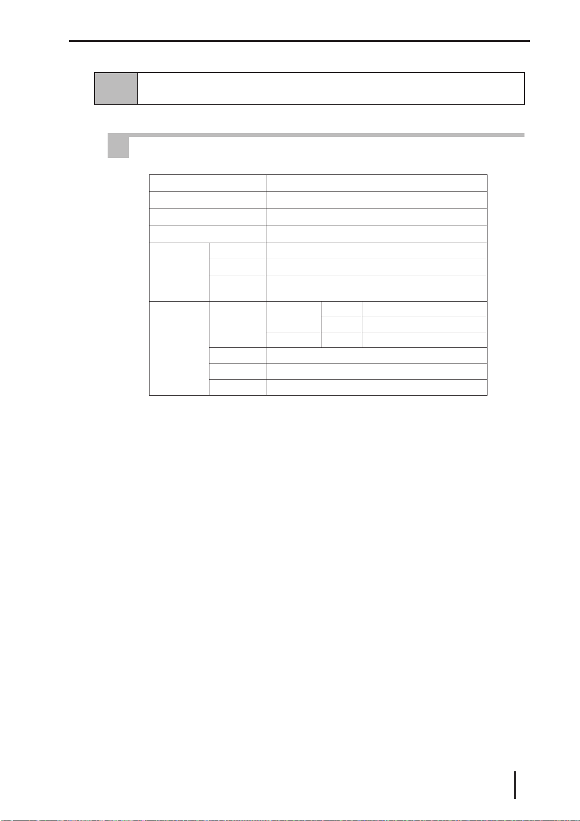
2-1 General Specifications
1 Electrical Specifications
2-4 PL External Features
2-5 PL Dimensions
Power supply
voltage 85 - 132 VAC, 50/60 Hz
Power
consumption PL-5700T1,PL-5700S1,PL-5700L1 :Max.150 VA
PL-5701T1, PL-5701S1, PL-5701L1: Max. 120 VA
Allowable
dropped voltage
time Max. 20 ms
Withstand
voltage 1500 VAC ,20 mmA for one minute (between charging terminal and FG
terminal)
Insulation
resistance Min. 10MW at500VDC (betweencharging terminaland FG terminal)

Specifications
2-2 PL-5700 Series User’s Manual
3 Dimensions
2 Environment Specifications
Be sure to check the specifications of any optional products used.
Also, if the temperature of the PL’s electrical cooling fins reaches 100 (+/- 15)
degrees, the PL’s saftety feature will automatically activate, turning the PL OFF.
Thus, since these fins are usually 25 degrees hotter than the surrounding
atmoshpere, once the area surrounding the PL reaches apporoximately 60 de-
grees, this safety feature will activate.
Once the temperature of these fins falls below 60 degrees, the unit can be re-
started and operation resumed.
Operating ambient
temperature PL-5700T1, PL-5701T1 : 0 ˚C 4 to 5˚C
PL-5700S1, PL-5701S1, PL-5700L1, PL-5701L1 : 0 ˚C to 40˚C
Ambient humidity 30%RH-85 %RH(noncondensing)
Storage temperature -10˚C to 60˚C
Operating ambient
atmosphere Free of corrosive gas
Noise immunity
(tested by noise
simulator)
Noise voltage : 1500Vp-p
Pulse duration : 50 ns, 500ns, 1µs
E lectrostatic
withstand voltage 5kV
Vibration resistance 2G:at10to25HzappliedinX,Y, and Z directions for 30 minutes each
(0.5 G when using HDD unit, and 1.0 G when using FDD unit)
Ground 100Ωorless,oryourcountry's applicable standard.
Rating Equivalent to IP65F(JEM1030)
External
dimensions PL-5700T1, PL-5700S1, PL-5700L1 : 321 mm (W) x 272 mm (H) x 129.3 mm (D)
PL-5701T1, PL-5701S1, PL-5701L1 : 321 mm (W) x 272 mm (H) x 96.3 mm (D)
Weight
PL-5700T1,PL-5700S1 :5.5 kg
PL-5701T1, PL-5701S1: 4.6kg
PL-5700L1 :4.7 kg
PL-5701L1: 3.8kg (excluding accessories)
Specifications
2-3
PL-5700 Series User’s Manual
2-2 Performance Specifications
1 Performance Specifications
CPU
AMD5x86(133MHz)manufacturedbyAMD
NDP
Not Applicable (Built into C PU)
DRAM(Main memory)
0MB(TwoDIMMsockets:Max.32MBmemory)
BIOS
Phoenix(PCcompatible)
Touch-pan-
el
Method Analogresistancefilm system
Resolution 1024 x 1024
Effective
area 10.4" screenand surrounding function-keyareas
Interface
Serial RS-232C C OM1 DB 9-pin male connector
C OM2 DB 9-pin male connector
RS-485 COM3 Terminalboard
Printer C entronics standard (DB 25-pin female connector)
Keyboard PS/2 interface (Mini DIN 6-pin female connector)
Mouse PS/2 interface (Mini DIN 6-pin female connector)

Specifications
2-4 PL-5700 Series User’s Manual
2 Display Functions
Backlight life is designated as the number of hours until the brightness drops to half
of the maximum level, in a 25°C environment. Before leaving images on the display
for an extended period of time, turn the backlight off if at all possible.
For information about how to replace the backlight, see “7-2 Replacing the 100V
Unit’s Backlight.”
ll
Display Colors
• Uneven brightness, flickering, or ghosts (caused by cross talk) may occur with the
PL-5700S1, PL-5701S1, PL-5700L1, and PL-5701L1, depending on the display col-
ors (especially halftones) or color combinations used. This, however, is a basic char-
acteristic of this type of display, not a defect. Since this flickering can sometimes be
caused by the combination of display colors used, selecting other colors may improve
the display quality.
• The higher the contrast between the foreground and background colors is, the more
likely that crosstalk will occur. Either changing the color combination or decreasing
the contrast may help to reduce the amount of cross talk.
See “5-2, System Parameters.”
PL-5700T1, PL-
5701T1 PL-5700S1,PL-
5701S1 PL-5700L1,PL-
5701L1
Display device TFT color LCD STN color LCD Black and white LCD
Pixel configuration 640x480pixels 640x480pixels 640x480pixels
Effective area 221.1(W) x158.4 (H)
mm 215.1 (W)x162.3 (H)
mm 216.0 (W)x160.8 (H)
mm
Dotpitch 0.33x 0.33 mm 0.33 x0.33mm 0.33x 0.33 mm
Color resolution 260,000colors 8 colors (halftone by
thinned-out frame) 2 colors (halftone by
thinned-out frame)
Contrastadjustment Fixed 8 levels 8 levels
Brightnessadjustment Fixed Fixed 2 levels
(Standard/High)
Maintenance
(backlight life) Replaceable backlight
lamp (20,000hours) Replaceable backlight
lamp (20,000hours)
Non-replaceable
backlight lamp
(Standard brightness :
45,000hours,
High brightness :
25,000hours)
Specifications
2-5
PL-5700 Series User’s Manual
II
For black-and-white displays : the PL-5700L1 and the PL-5701L1
• These displays normally use only black and white,
with grey tones being produced by making the dots
flash. This display method, however, may cause flick-
ering to occur with certain halftones.
• If VGA 16-color standard pallet colors are used on a
black-and-white display, brightness will increase in
order of the pallet numbers, i.e. from 0 (black) to 15
(white). It is not recommended to use those colors
marked with asterisks (*) (shown in the figure to the
right), since they often cause flickering.
• Pallet colors 2, 6, and 9 may be hard to identify on
the screen, since they have almost the same level of
brightness.
• Some combinations of colors may not be easy to iden-
tify. Whenever you are developing an application it
is recommended that you frequently test how your
program will appear on the PL.
• Black-and-white tiled displays often appear better
than multi-colored displays.
• If you wish to use halftones, be sure to check their
display quality during actual PL operation.
III
STN color LCD displays: PL-5700S1 and PL-5701S1
• STN color LCDs use three primary colors - red, green, and blue - to display up to
8 different colors. Halftones are produced by making the dots used in these three
colors flash. This mechanism, however, may cause flickering with certain half-
tones.
• Tiled displays using only pure colors - black, red, green, blue, yellow, magenta,
cyan, and white (pallet numbers 0, 12, 10, 9, 14, 13, 11, and 15) - may appear
better than displays using different colors.
• If you wish to use halftones, be sure to check their display quality during actual
PL operation.
VGA 16-color standard pallet
Darker
Brighter
^
^
0Black Dark
1Blue Dark *
4Red Dark *
5 Magenta Dark *
8Black Bright
6 Yellow Dark *
2Green Dark
9Blue Bright
3Cyan Dark *
12Red Bright
13 Magenta Bright
7White Dark
10Green Bright *
11Cyan Bright *
14 Yellow Bright *
15 White Bright
Specifications
2-6 PL-5700 Series User’s Manual
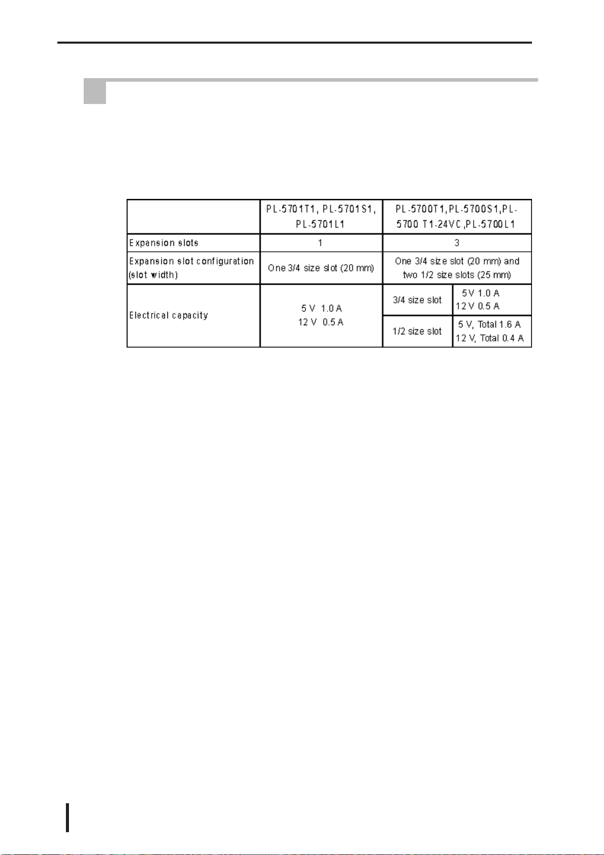
3 Expansion Slots
• The PL does not supply -5 or -12 V. As a result, ISA (AT) bus compatible boards
which require -5 or -12 V are not available.
• All the DB connectors for external interfaces are equipped with inch type connector
screw threads.
This manual suits for next models
7
Table of contents
Other Pro-face Desktop manuals


