Please note that any damage, including chips and scratches, that occurs at the job site is
excluded from the warranty coverage.
Properly installing drain components is the sole responsibility of the installer. Streamline
does not provide warranty coverage for leaks associated with improper waste installation.
Streamline is not liable for defects or issues that arise or could have been prevented by
inspecting and testing all plumbing connections for leaks before completing the
installation.
Streamline shall not be held liable for any and all fees stemming from the cost of
installation, re-installation, removal, subsequent damage, or transportation in the case of
a product defect. Streamline shall not be held responsible for defects or damage that
could have been discovered, repaired, or avoided by inspection and testing before
installation.
Before finalizing installation, ensure all plumbing connections are tested, and checked
for leaks. Streamline will not be held responsible for defects or issues that arise from
neglecting this crucial step.
Please be aware that the following are general installation guidelines.
Depending on the specific bathtub model purchased, you may need to adjust
the length of the pipes to fit the bathtub properly. If necessary, use a plastic
drainpipe cutter for any required modifications.
Attach the strainer upper gasket (Q) to the strainer (C). Spread silicone sealant
(not included) along the underside flange of the strainer (C). Align the drain
elbow (D) and the rubber drain washer (E) from underneath the bathtub drain
hole. Insert the strainer (C) into the drain hole and securely attach it from
underneath the bathtub to the rubber drain washer (E) and to the drain
elbow (D). Use pliers or a strainer wrench (not included) to tighten it.
. Position a slip nut (G) and washer (H) onto the drain elbow (D), orienting the
threads of the slip nut and the beveled edge of the washer toward the end of
the tube.
Slide a slip nut (G) and washer (H) onto the overflow elbow (A), ensuring that
the threads of the slip nut and the beveled edge of the washer are oriented
toward the end of the tube.
Next, position the rubber overflow washer (B) onto the overflow elbow (A),
with the thicker lip facing the overflow elbow’s upper part, as indicated in the
drawing.
Insert the longer arm of the retainer clips (Y) into the slots located just below
the screw holes on the overflow elbow (A).
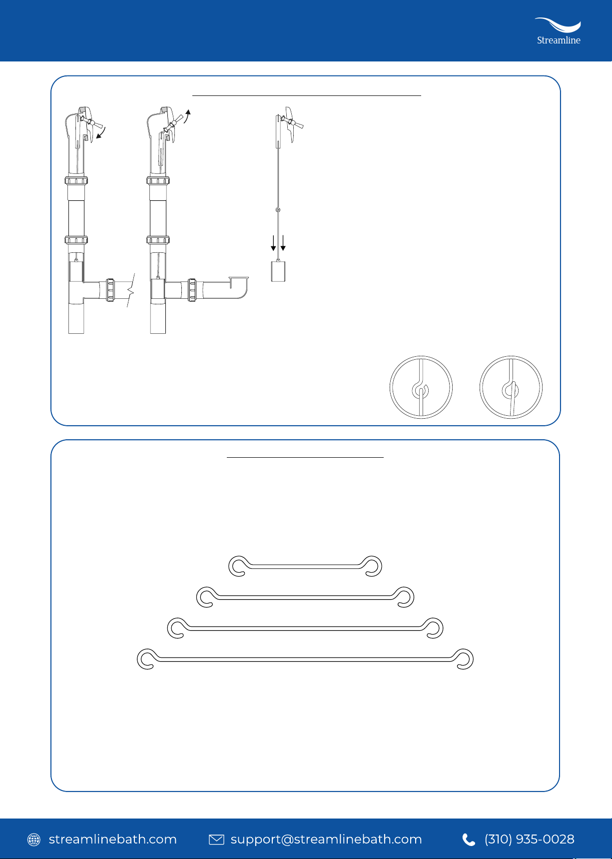
BATHTUB DRAIN INSTALLATION INSTRUCTIONS
Measure from the center of the overflow hole to the bottom of the bathtub,
where the drain elbow (D) will connect to the waste tee (F). Determine if the
extension tube (N) is needed based on the measured height.
Installation Instructions