Street Guardian SGDCHW User manual

SGdchw & SGX2HW
Hardwire KITs
User MANUAL

1
Product safety & precautions
Thank you for purchasing the Street Guardian Hardwire Kit. Please read
and follow this guide before installation and use.
When installing the hardwire kit, please avoid any safety related power
sources such as airbags in the fuse box.
Please ensure that your Street Guardian camera is updated to the latest
firmware available for download from the support section of our
website.
Please use only the included Street Guardian accessories or approved
replacements from a Street Guardian dealer. Use of non-approved
accessories may damage your product or your vehicle and may void
your warranty. Street Guardian supplied accessories are tested to
meet or exceed recognized testing standards worldwide to ensure
reliable performance of your product.
Professional installation is recommended to ensure correct operation.

2
INTRODUCTION
The Street Guardian Hardwire Kit enables a special parking mode
function for the supported camera models. Installation of this product
provides the camera with a source of power from the vehicle’s battery
while the ignition is off. A built-in power monitoring system will
terminate power before low voltage discharge can occur to the vehicle’s
battery.
Parking mode is automatically activated when your vehicle’s ignition is
off and will enter time lapse recording which the user can select from
three available frame rate options; 1, 3, or 5 FPS.
An adjustable timer function determines the duration of parking mode
recording and the power supply from the vehicle’s battery.
If your vehicle’s battery begins to drain below an adjustable voltage
threshold, power and parking mode recording will automatically
terminate in order to maintain sufficient reserve battery power.

3
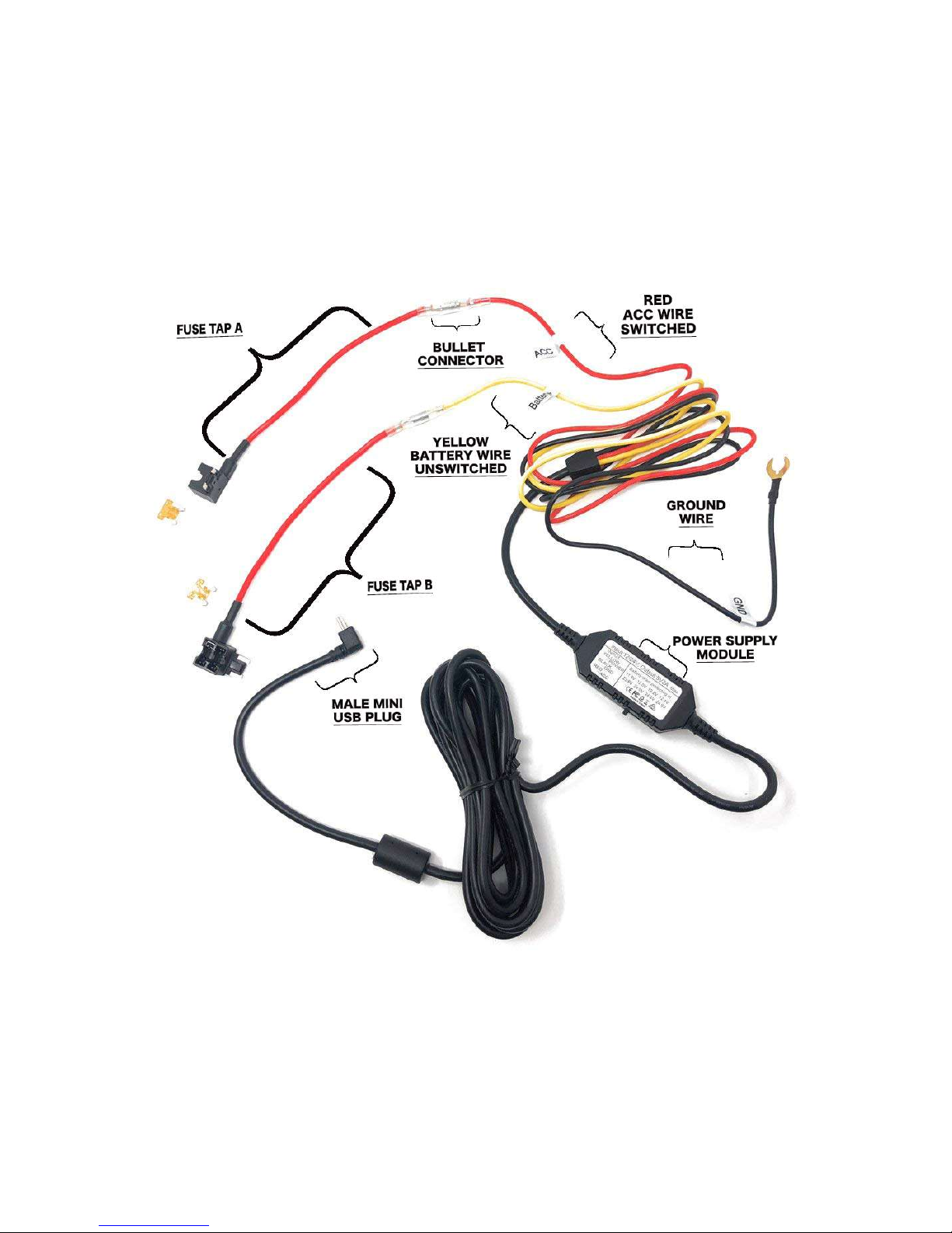
HARDWIRE LAYOUT & OVERVIEW
* [Note] Fuse tap may vary, example shown is Low Profile Mini, SGDCHW shown

4
SELECTING A LOW VOLTAGE CUTOFF
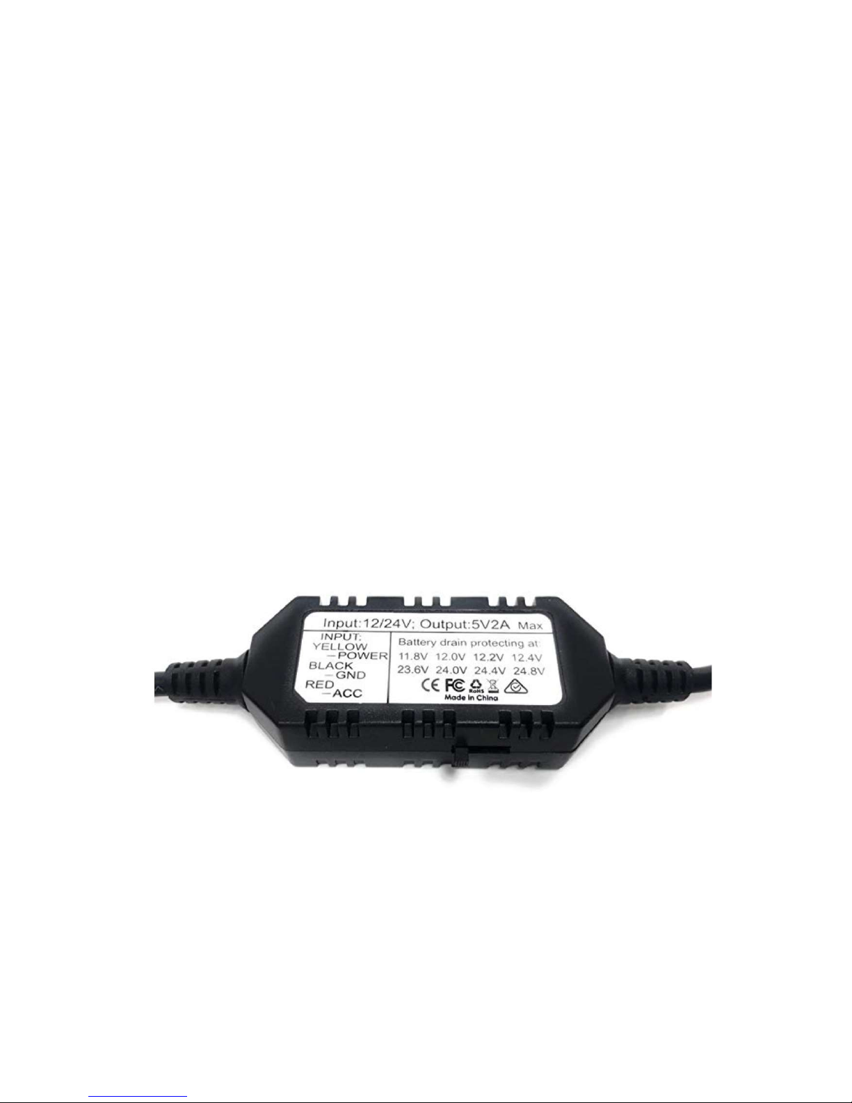
This hardwire kit has a nominal input voltage of 12v~24v. The power
supply module has a four-position dip-switch for the cut off voltage
threshold of your vehicle’s battery. Once the threshold has been set,
power will be automatically terminated if power consumption from the
main DVR drains the battery beyond this point.
As a reference, please use the top row [11.8v, 12.v, 12.2v, 12.4v] for 12V
batteries, and the bottom row [23.6v, 24.0v, 24.4v, 24.8v] for 24V
batteries, input voltage detection is automatic.
In colder conditions, we recommend selecting a higher voltage threshold
on the dip-switch to ensure optimal reserve power.
Please note that the duration of parking mode recording is decreased in
direct proportion to the increase of the voltage cut off threshold. The
highest voltage threshold setting will result in a lower recording duration
to provide a wider breadth of reserve power for your vehicle’s battery.

5
FUSE TYPE
Before purchasing the hardwire kit, it’s important to select the correct
fuse type. Please refer to your vehicle owners manual and locate an
appropriate fuse in your fuse panel that is not part of your vehicle’s
safety power systems such as airbags, horn, etc, professional installation
is recommended.

6
PARKING MODE MENU SETTINGS
It is necessary to configure your camera to accept the hardwire kit.
Please ensure that your camera is updated to the latest firmware
available from the support section of our website.
Once the firmware update in complete, please select Power Output to
3-wire. Once the hardwire kit is installed and connected to the camera,
two additional options will be accessible in the camera’s menu.
The Parking Monitor menu allows you to select the frame rate for time
lapse recording. The options available are 1fps, 2fps, and 5fps, lower
frame rates use less storage space, higher frame rates will offer more
detail.
The Shutdown Timer menu allows you to select the amount of time
parking mode will be active for. The range of options available are 5, 10
and 30 minutes, as well as 1, 2, 3, 4, 6, 12, 18 and 24 hours.

7
To indicate that parking mode has been engaged, a clock icon “ ” will
appear near the top right of the screen and an audio jingle will be heard
when entering or exiting parking mode.

8
FAQ
1. Camera is not powering on once the hardwire installed.
If you’re confident that the hardwire kit is receiving power, please
ensure that the camera is updated to latest firmware and the
power input in the settings menu is set to 3 wire.
Note: it is necessary to start the vehicle after installing to allow the
hardwire kit to detect the default voltage and set a reference
voltage level.
2. How to select the best fuse to tap into?
The best resource is always your vehicle’s instruction manual,
however if you no longer have the manual please use the following
websites to access a schematic of your vehicle’s fuse panel and
function of each fuse:
http://www.autogenius.info
https://fuse-box.info/
http://fusesdiagram.com/

9
3. How to turn the camera off while parked?
After the vehicle has been turned off and the camera has entered
parking mode press and hold the power button to shutdown the
camera
4. How to turn camera back on in parking mode?
The camera can be turned back on while in parking mode manually
by long pressing the power button.
Note: if turning the camera back on while parked the camera will
record in normal mode and the shutdown timer settings will not
apply, restarting the vehicle will return the camera to its normal
operating mode.

10
Technical SPECIFICATIONS
Input voltage (Nominal) 12v~24v Auto detecting
Output voltage 5v 2A
12v Voltage cutoff (+/- 0.1v) 11.8v, 12.0v, 12.2v, 12.4v
24v Voltage cutoff (+/- 0.1v) 23.6v, 24.0v, 24.4v, 24.8v
Cable length 4 meters (13 ft & 1.5 inch)
Length from Camera to Module 3 meters (9 ft & 10.125 inch)
Length from Module to Fuse Tap 1 meter (3ft & 3.375 inch)
Recommended fuse 5A

11
further information
All attempts are made to ensure that the information contained in
this user guide is correct at time of publication.
The specifications and details within this guide are based on the
Australian market version of the product and are subject to change,
the pictures used are for illustration purposes only.
Information about the latest specification, any amendments, the
availability of replacement parts and accessories, warranty
information, detail of other sales region product specification and
the respective user manuals will be listed on the support section of
our website https://streetguardian.info/support/
[Note] Specification and features are subject to improvement
www.streetguardian.info
© Street Guardian 2018
This manual suits for next models
1
Table of contents