Stromberg-Carlson 450 Dimension Guide
ENGINEERING
DATA
STROMBERG-CARLSON
NO.
450
RADIO
RECEIVERS
STROMBERG-CARLSON
TELEPHONE
MANUFACTURING
COMPANY
ROCHESTER,
NEW
YORK
P-30876
Issue
1
Printed
in
U.
S.
A.

IDENTIFICATION
TABLE
Model
Input
Power
Frequency
Chassis
Cabinet
Speaker
450-M
.
50-60
Cycles
30162
30164
27504
450-MB
.
25-60
Cycles
30163
30164
27504
SPECIFICATIONS
Type
of
Circuit.
.
Tuning
Ranges...
Number
of
Tubes
Type
of
Tubes...
Voltage
Rating...
Power
Frequency
Rating.
Input
Power
Rating.
Intermediate
Frequency.
Speaker
Voice
Coil
Impedance
at
400
Cycles
Speaker
Field
Coil
Resistance.
.Superheterodyne
with
Electric
Tuning
A—.53
to
1.7
Me.;
B—2.3
to
7.5
Me.;
C—7.5
to
23
Me.
.
Eleven
.6K7,
R.
F.
Amplifier
6A8,
Modulator
6J5,
Oscillator
6K7,
I.
F.
Amplifier
6H6,
Demodulator
6SQ7,
Audio
Amplifier
6SQ7,
Audio
Inverter
6F6G,
Output
(2)
5Z3,
Rectifier
6AF6G,
Tuning
Indicator
.105
to
125
Volts
-Standard
50-60
Cycles,
also
available
25-60
Cycles
.120
Watts
.455
Kilocycles
.Approximately
1.5
Ohms
.505
Ohms
General
FEATURES
This
is
an
eleven
tube,
three
gang,
three
band,
high
fidelity
receiver,
designed
for
operation
with
the
Stromberg-Carlson
senior
Acoustical
Labyrinth
and
Carpinchoe
Speaker.
The
chassis
is
of
the
fortified
type
with
bails
provided
for
ease
in
handling
and
servicing.
Auto¬
matic
tuning
is
accomplished
by
means
of
a
motor
drive
controlled
by
a
commutator
and
brush
assembly,
and
the
dial
is
of
the
slide
rule
type,
edge-lighted
for
clear
visibility
without
glare.
Separate
treble
and
bass
controls
are
provided
to
make
possible
accurate
adjustment
of
the
tone,
and
the
chassis
is
designed
to
be
easily
converted
for
use
with
remote
control
or
phonograph.
This
chassis
is
designed
to
provide
the
maximum
in
sensitivity
and
selectivity
and
excellent
tone
quality
for
the
discriminating
customer.
It
should
also
be
relatively
free
from
the
“birdies,
tweets
and
whistles”
and
interference
of
the
type
found
in
some
smaller
sets.
Special
Circuits
A
tuning
indicator
having
two
apertures,
one
for
strong
signals
and
one
for
weak
signals,
is
used
with
this
chassis.
One
aperture
will
close
with
a
signal
of
approximately
100,000
microvolts,
and
the
other
will
not
close
even
with
a
two
volt
signal.
Iron
core
coils
are
used
in
the
IF
and
RF
circuits
to
provide
greater
stability
and,
in
addition,
a
thermal
drift
compensator
is
included
in
the
circuit.
The
high
frequency
end
of
each
band
is
spread
out
by
means
of
special
capacitor
plates,
to
pro¬
vide
greater
ease
in
tuning
and
automatic
low
level
bass
compensation
is
provided.
The
audio
system
employs
a
special
inverter
push-pull
circuit
designed
to
provide
excellent
fidelity
and
the
chassis
is
thoroughly
shielded
throughout
with
an
electro-statically
shielded
power
transformer.
Automatic
Tuning
Twelve
push
buttons
are
provided.
From
right
to
left
their
operation
is
as
follows:
1
Manual
Control
2
Remote
Control
3-10
Pre-set
Stations
(8)
11
Phonograph
12
Off
Switch
1
Pushing
any
button
(except
the
Off
button)
turns
the
set
on
and
tuning
is
accomplished
by
means
of
an
electric
motor
driving
the
regular
variable
capacitor
to
a
pre-set
point.
Setup
is
very
easily
accomplished
by
means
of
a
switch
which
causes
the
pilot
light
to
go
out
when
the
brush
is
properly
located.
Remote
Control
Remote
selection
of
stations
may
be
accomplished
by
simply
plugging
the
remote
control
box
into
the
socket
provided
on
the
back
of
the
chassis
and
a
motor
to
control
the
volume
can
be
readily
attached
to
the
volume
control
shaft.
The
identifying
number
of
the
package
containing
the
remote
control
box,
motor
and
all
neces¬
sary
parts
is
30387
for
50-60
cycles
and
30391
for
25
cycles.
Phonograph
Operation
A
socket
is
provided
on
the
back
of
the
chassis
into
which
a
record
player
may
be
plugged,
and
a
switch
is
provided
on
the
front
of
the
chassis
for
switching
from
“Radio”
to
“Phonograph”.
Television
Switching
to
“Phonograph”
also
makes
the
audio
amplifier
and
loud
speaker
available
for
use
with
television
receivers
designed
for
this
type
of
sound
reproduction.
ACCESSORIES
Antenna
For
best
results
use
a
Stromberg-Carlson
Antenna.
These
Antennas
are
supplied
in
kits
con¬
taining
all
the
necessary
parts
for
mounting
and
installation
and
are
designed
especially
for
use
with
all
Stromberg-Carlson
receivers.
Playing
Records
To
obtain
the
best
quality
of
phonograph
reproduction
a
Stromberg-Carlson
record
player
is
recommended.
They
are
designed
for
use
with
this
receiver,
and
all
that
is
necessary
is
to
con¬
nect
the
record
player
to
the
single
prong
socket
provided
in
the
chassis
and
proceed
to
operate.
The
volume
and
tone
may
be
controlled
with
the
controls
at
the
receiver,
or
(if
such
is
pro¬
vided)
the
volume
control
on
the
record
player
may
be
used.
A
low
impedance
pick-up
may
also
be
used,
but
a
matching
transformer
must
be
placed
be¬
tween
the
phonograph
pick-up
and
the
chassis.
Remote
Control
Stromberg-Carlson
has
prepared
a
“Remote
Tuning
Control
Unit”
which
may
be
easily
installed
on
these
receivers.
This
Unit
enables
the
user
to
select
any
one
of
the
eight
favorite
stations
which
have
been
previously
set
up
on
the
electric
tuning
system
at
a
distance
from
the
receiver
up
to
the
length
of
the
attached
cable.
A
motor
and
two
push
buttons
are
also
included
for
controlling
the
volume.
These
units
complete
with
accessories
and
installation
instructions
are
available
in
package
assemblies
P.
30387
for
use
with
50-60
cycle
receivers
and
P.
30391
for
use
with
25
cycle
receivers.
Headset
Attachment
Headphones
can
be
very
simply
attached
to
this
receiver.
Ask
for
Pc.
No.
28303
Headset
Package
Assembly,
which
comes
complete
with
headphones
and
installation
instructions.
Care
of
Cabinet
The
finish
of
Stromberg-Carlson
Cabinets
should
be
protected
by
using
Stromberg-Carlson
Cabinet
Polish
regularly.
It
is
available
in
pint
cans,
designated
as
Pc.
No.
28601.
Nicks
and
scratches
of
most
kinds
can
be
repaired
quickly
and
easily
by
proper
use
of
the
Pc.
No.
26962
Touch-Up
Kit.
Complete
instructions
are
provided
with
each
kit.
Tools
Stromberg-Carlson
can
supply
all
the
tools
required
for
working
on
these
sets.
For
example:
SD-29
Phillips
Head
Screwdriver
No.
24608
Aligning
Tool
Also
pliers,
cutters,
screwdrivers,
etc.
2
ALIGNING
INFORMATION
NEVER
ALIGN
UNLESS
ABSOLUTELY
NECESSARY.
Use
a
good
modulated
signal
generator
(test
oscillator)
with
variable
output
voltage
and
a
sen¬
sitive
output
meter
across
the
voice
coil
of
the
speaker.
Always
align
using
the
smallest
possible
input
from
the
signal
generator
(except
when
wave
trap
adjustment
is
made).
A
strong
signal
makes
adjustments
inaccurate.
Always
have
receiver
volume
control
full
on.
Never
align
with
tone
control
in
“Bass”
position.
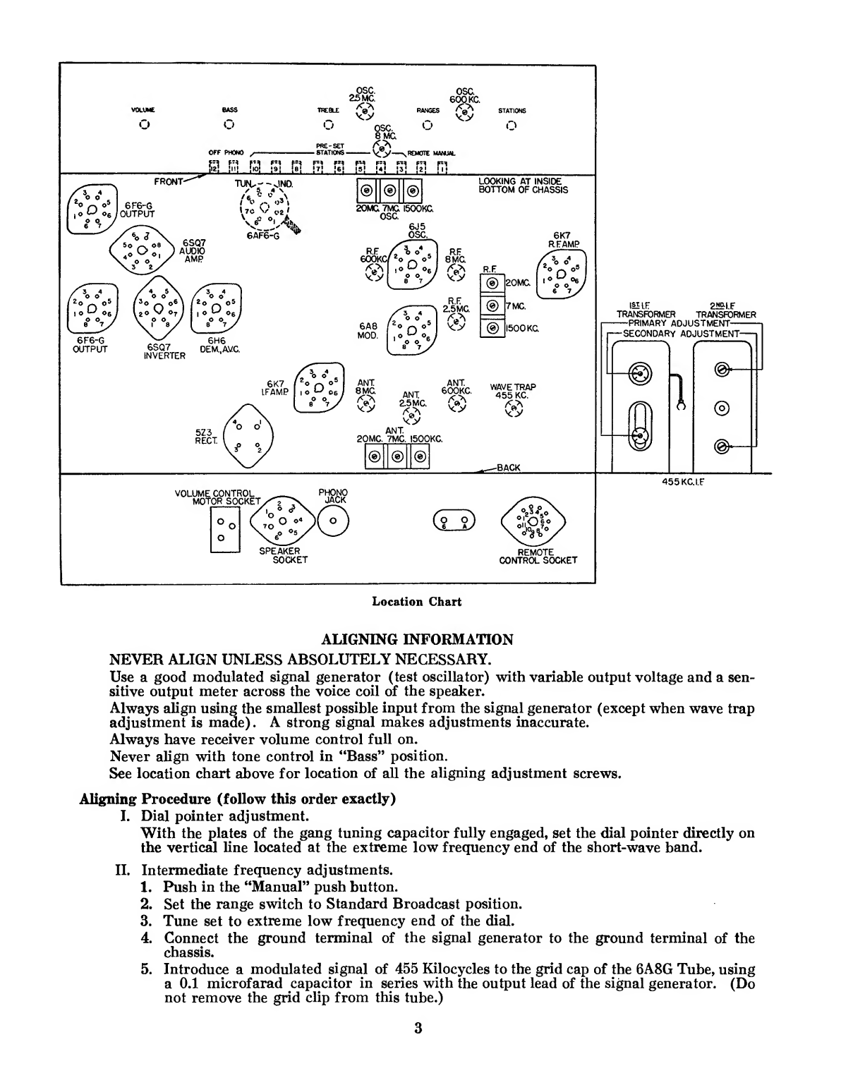
See
location
chart
above
for
location
of
all
the
aligning
adjustment
screws.
Alig
n
in
g
Procedure
(follow
this
order
exactly)
I.
D
ial
pointer
adjustment.
With
the
plates
of
the
gang
tuning
capacitor
fully
engaged,
set
the
dial
pointer
directly
on
the
vertical
line
located
at
the
extreme
low
frequency
end
of
the
short-wave
band.
II.
Intermediate
frequency
adjustments.
1.
Push
in
the
“Manual”
push
button.
2.
Set
the
range
switch
to
Standard
Broadcast
position.
3.
Tune
set
to
extreme
low
frequency
end
of
the
dial.
4.
Connect
the
ground
terminal
of
the
signal
generator
to
the
ground
terminal
of
the
chassis.
5.
Introduce
a
modulated
signal
of
455
Kilocycles
to
the
grid
cap
of
the
6A8G
Tube,
using
a
0.1
microfarad
capacitor
in
series
with
the
output
lead
of
the
signal
generator.
(Do
not
remove
the
grid
clip
from
this
tube.)
3
6.
A
d
just
the
L
F.
Aligners
for
maximum
output
in
the
following
order:
A.
Secondary
of
second
I.
F.
transformer.
B.
Primary
of
second
L
F.
transformer.
C.
Secondary
of
first
I.
F.
transformer.
D.
Primary
of
first
I.
F.
transformer.
IIL
Radio
frequency
adjustments.
Short
Wave
Range
(C
Band)
1.
Replace
the
0.1
microfarad
capacitor
in
series
with
the
output
lead
of
the
signal
gen¬
erator
with
a
400
ohm
carbon
type
resistor,
and
connect
it
to
the
antenna
terminal
of
the
chassis.
2.
Set
the
range
switch
to
the
short-wave
range
position
(C
Band).
3.
Set
the
signal
generator
frequency
and
the
receiver
tuning
dial
to
8
megacycles.
4.
Adjust
the
8
megacycle
oscillator
R.
F.
and
antenna
iron
cores
for
maximum
signal.
5.
Set
the
signal
generator
frequency
and
the
receiver
tuning
dial
to
20
megacycles.
6.
Adjust
the
20
megacycle
oscillator
R.
F.
and
antenna
aligning
capacitors
for
maximum
signal.
7.
Repeat
operations
three
and
four.
8.
Repeat
operations
five
and
six.
Medium
Wave
Range
(B
Band)
1.
Leave
the
receiver
connected
in
the
same
manner
as
when
adjusting
the
Short-Wave
Range
(GBand).
2.
Set
the
range
switch
to
the
medium
wave
range
position
(B
Band).
3.
Set
the
signal
generator
frequency
and
the
receiver
tuning
dial
to
2.5
megacycles.
4.
Adjust
the
2.5
megacycle
oscillator,
R.F.
and
antenna
iron
cores
for
maximum
signal.
5.
Set
the
signal
generator
frequency
and
the
receiver
tuning
dial
to
7.0
megacycles.
6.
Adjust
the
7
megacycle
oscillator,
R.
F.
and
antenna
aligning
capacitors
for
maximum
signal.
7.
Repeat
operation
three
and
four.
8.
Repeat
operation
five
and
six.
Standard
Broadcast
Range
(A
Band)
1.
Replace
the
400
ohm
carbon
type
resistor
in
series
with
the
output
lead
from
the
signal
generator
with
a
200
micro-microfarad
capacitor.
2.
Set
the
range
switch
to
the
Standard
Broadcast
Range
(A
Band).
3.
Set
the
signal
generator
frequency
and
the
receiver
tuning
dial
to
600
Kc.
4.
Adjust
the
600
Kc.
oscillator
R.
F.
and
antenna
iron
cores
for
maximum
signal.
5.
Set
the
signal
generator
frequency
and
the
receiver
tuning
dial
to
1500
Kc.
6.
Adjust
the
1500
Kc.
oscillator
R.
F.
and
antenna
aligning
capacitors
for
maximum
signal.
7.
Repeat
operation
three
and
four.
8.
Repeat
operation
five
and
six.
IV.
Wave
Trap
Adjustment.
(Leave
the
receiver
connected
in
the
same
manner
as
when
adjusting
the
Standard
Broad¬
cast
Range
(“A”
Band)
).
1.
Tune
set
to
1000
Kc.
2.
Set
the
signal
generator
frequency
to
455
Kc.
and
introduce
a
fairly
strong
modulated
signal
to
the
receiver.
3.
Adjust
the
wave
trap
aligner
for
minimum
signal.
ADJUSTING
DIAL
LAMP
The
dial
on
this
receiver
is
edge
lighted,
and
for
proper
illumination
it
is
very
important
that
the
dial
light
be
adjusted
so
that
the
filament
is
exactly
opposite
the
edge
of
the
glass.
To
make
this
adjustment
simply
slide
the
pilot
light
socket
back
and
forth
on
its
mounting
bracket
until
maximum
illumination
is
obtained.
4
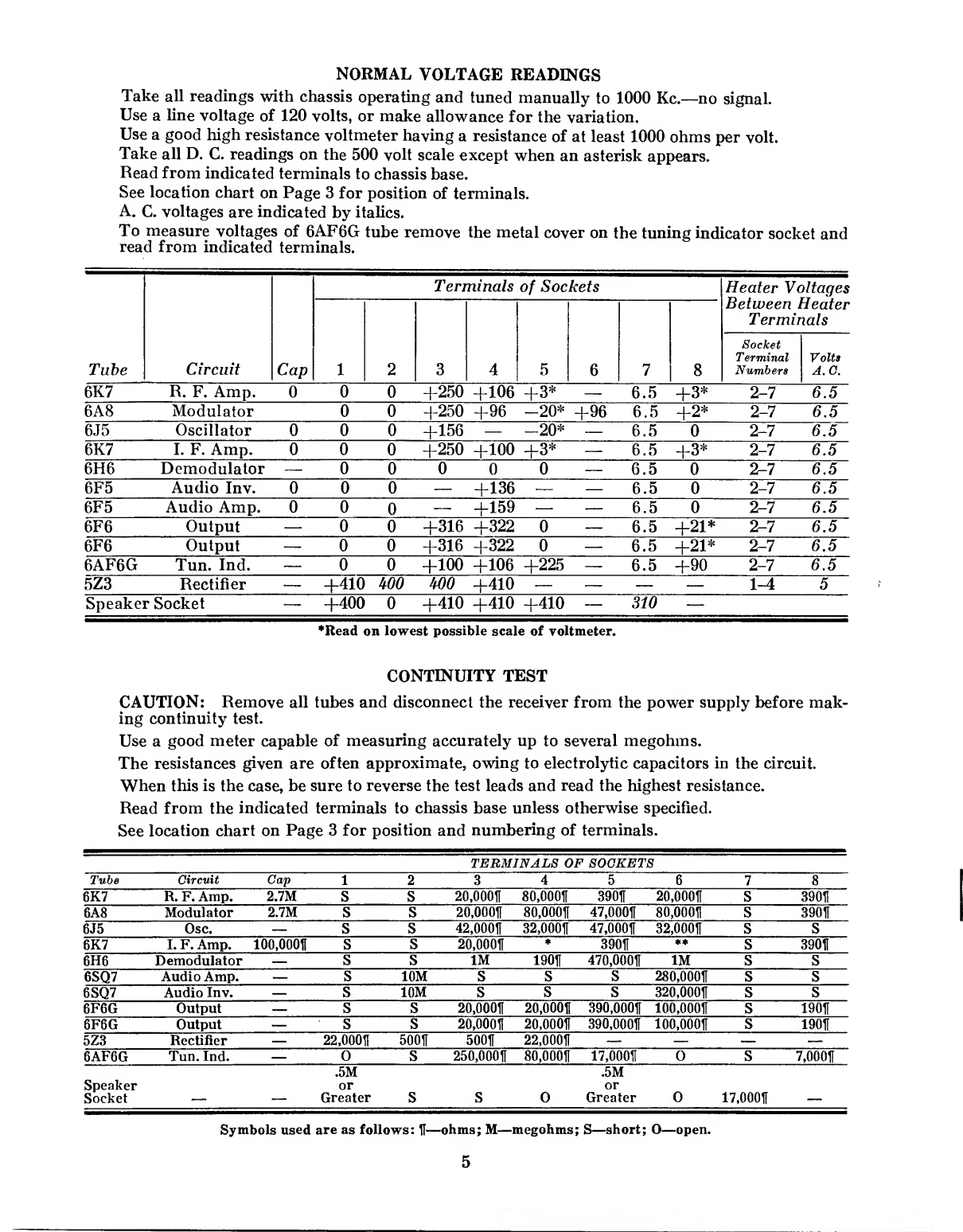
NORMAL
VOLTAGE
READINGS
Take
all
readings
with
chassis
operating
and
tuned
manually
to
1000
Kc.—no
signal.
Use
a
line
voltage
of
120
volts,
or
make
allowance
for
the
variation.
Use
a
good
high
resistance
voltmeter
having
a
resistance
of
at
least
1000
ohms
per
volt.
Take
all
D.
C.
readings
on
the
500
volt
scale
except
when
an
asterisk
appears.
Read
from
indicated
terminals
to
chassis
base.
See
location
chart
on
Page
3
for
position
of
terminals.
A.
C.
voltages
are
indicated
by
italics.
To
measure
voltages
of
6AF6G
tube
remove
the
metal
cover
on
the
tuning
indicator
socket
and
read
from
indicated
terminals.
Tube
Circuit
Terminals
of
Sockets
Heater
Voltages
1
2
6
1
8
aetween
Ter
mir
Socket
Terminal
Numbers
heater
mis
Volts
A.C.
6K7
R.
F.
Amp.
MiM
0
+250
+106
+3*
—
6.5
+3*
2-7
6.5
6A8
Modulator
0
0
+250
+96
—20*
+96
6.5
+2*
2-7
6.5
6J5
Oscillator
0
0
0
+156
—
-20*
—
6.5
0
2-7
6.5
6K7
I.
F.
Amp.
0
0
0
+250
+100
+3*
—
6.5
+3*
2-7
6.5
6H6
Demodulator
—
0
0
0
0
0
—
6.5
0
2-7
6.5
6F5
Audio
Inv.
0
0
0
—
+136
—
—
6.5
0
2-7
6.5
6F5
Audio
Amp.
0
0
0
—
+159
—
—
6.5
0
2-7
6.5
Output
—
0
0
+316
+322
0
—
6.5
+21*
2-7
6.5
2
I
3
QH
Output
—
0
0
+316
+322
0
—
6.5
+21*
■
*5911
6.5
6AF6G
Tun.
Ind.
—
0
0
+100
+106
+225
—
6.5
+90
6.5
5Z3
Rectifier
—
+410
m
m
+410
—
—
—
—
1-4
5
Speaker
Socket
—
+400
0
+410
+410
+410
—
310
—
*Read
on
lowest
possible
scale
of
voltmeter.
CONTINUITY
TEST
CAUTION:
Remove
all
tubes
and
disconnect
the
receiver
from
the
power
supply
before
mak¬
ing
continuity
test.
Use
a
good
meter
capable
of
measuring
accurately
up
to
several
megohms.
The
resistances
given
are
often
approximate,
owing
to
electrolytic
capacitors
in
the
circuit.
When
this
is
the
case,
be
sure
to
reverse
the
test
leads
and
read
the
highest
resistance.
Read
from
the
indicated
terminals
to
chassis
base
unless
otherwise
specified.
See
location
chart
on
Page
3
for
position
and
numbering
of
terminals.
TERMINALS
OF
SOCKETS
Tube
Circuit
Cap
1
2
3
4
5
6
7
8
R.
F.
Amp.
2.7M
s
S
20,000ft
80,000ft
390ft
20,000ft
s
390ft
6A8
Modulator
2.7M
s
S
20,000ft
80,000ft
47,000ft
80,000ft
s
390H
Osc.
—
s
S
42,000ft
32,000ft
47,000ft
32,000ft
s
s
fflsmm
I.
F.
Amp.
100,000ft
s
S
♦
**
s
390ft
Demodulator
—
s
S
1M
190H
470,000ft
1M
s
S
6SQ7
Audio
Amp.
—
s
10M
S
s
S
280,000ft
s
s
6SQ7
Audio
Inv.
—
s
10M
S
s
s
320,000ft
s
s
6F6G
Output
—
s
S
20,000ft
20,000ft
390,000ft
100,000ft
s
19011
6F6G
Output
—
s
s
20,000ft
20,000ft
390,000ft
100,000ft
s
190H
5Z3
Rectifier
—
22,000ft
500ft
500ft
22,000ft
—
—
—
—
6AF6G
Tun.
Ind.
—
0
s
250,000ft
80,000ft
17,000ft
0
s
7,000ft
Speaker
Socket
,5M
or
Greater
s
s
0
.5M
or
Greater
0
17,000ft
Symbols
used
are
as
follows:
ft—ohms;
M—megohms;
S—short;
O—open.
5

*
Push
“Phono”
button
in—“open”.
Push
“Manual”
button
in—100,000
ohms.
**
Push
“Phono”
button
in—“open”.
Push
“Manual”
button
in—32,000
ohms.
Other
tests
not
shown
on
chart
Test
from
phono
jack
on
back
of
chassis
base;
Push
“Phono”
button
in—1
megohm.
Push
“Manual”
button
in—“open”.
Antenna
terminal
to
chassis
base—70
ohms.
Ground
terminal
to
chassis
base—“short”.
Test
between
terminals
of
A.
C.
plug;
Push
“Off”
button
in—“open”.
Push
“Manual”
button
in—3
ohms.
Terminals
of
A.
G.
plug
to
chassis
base—“open”.
R.
F.
coil
tests
measured
directly
across
R.
F.
coil
terminals
with
range
switch
set
in
standard
position
(A
Band).
LI—1
ohm,
L2—3
ohms,
L3—.2
ohm,
L4—.2
ohm,
L5—.2
ohm,
L6—“short”,
L7—70
ohms,
L8—“short”,
L9—1
ohm,
L10—.2
ohm,
Lll—.3
ohm,
L12—.5
ohm,
L13—.1
ohm,
L14—
.5
ohm,
L15—4
ohms,
L16—.2
ohm,
L17—.3
ohm,
L18—.2
ohm,
L19—.2
ohm.
INSTRUCTIONS
FOR
SETTING
UP
PUSH
BUTTONS
IMPORTANT:
The
stations
selected
should
be
the
local
or
favorite
stations
which
give
good
reception
at
all
times.
Set
up
stations
in
the
daytime
to
avoid
unnecessary
interference.
Allow
the
set
to
run
for
about
twenty
minutes
before
setting
up
stations.
Always
use
the
tuning
indicator
unit
when
setting
up
stations
in
order
to
determine
when
the
station
is
exactly
in
tune.
1.
Put
the
call
letters
of
the
selected
stations
in
place
above
the
push
buttons.
The
stations
should
be
arranged
according
to
frequency
with
the
highest
frequency
at
the
right
and
the
lowest
frequency
at
the
left,
just
as
on
the
dial.
(The
call
letters
will
be
found
inside
the
envelope
stapled
inside
or
underneath
the
cabinet).
2.
Set
the
“Treble”
control
in
normal
position.
3.
Turn
the
set-up
switch
(located
on
the
base
just
back
of
the
brush
and
commutator
assem¬
bly)
to
the
set-up
position.
(The
slot
in
the
screw
should
point
toward
“set-up”).
4.
Push
the
button
of
the
highest
frequency
station
to
be
set
up
(button
No.
3)
and
then
tune
in
that
station
manually.
Be
sure
the
station
is
exactly
“in
tune”
by
tuning
carefully
and
watching
the
cathode
ray
indicator.
5.
Slide
the
brush
to
which
the
blue
wire
is
connected
until
it
is
over
the
slot
in
the
commu¬
tator.
Then
adjust
it
very
carefully
until
the
pilot
light
goes
out.
This
indicates
exact
ad¬
justment.
6.
Repeat
operations
4
and
5
for
each
station.
Work
from
right
to
left
or
from
the
higher
to
the
lower
frequencies
in
accordance
with
the
table
below:
Push
Button
No.
Purpose
Color
of
wire
on
brush
1
2
3
4
5
6
7
8
9
10
11
12
Manual
Remote
Highest
frequency
station
Next
lower
frequency
station
Next
lower
frequency
station
Next
lower
frequency
station
Next
lower
frequency
station
Next
lower
frequency
station
Next
lower
frequency
station
Lowest
frequency
station
Phonograph
Off
Blue
Orange
Green
Brown
Slate
Red
Black
Blue
White
f
See
diagram
on
last
page.
7.
Turn
the
set-up
switch
back
to
the
“Operate”
position.
8.
Check
the
operation
of
all
the
push
buttons
to
be
sure
that
each
has
been
accurately
set
up.
If
it
is
necessary
to
readjust
any
of
the
buttons,
follow
the
procedure
given
above.
6

£*UBL
6A
8
MQO
.
-fi&Llf.
6H6
PEMAV.fi
ASfll
AUP1Q.AML
7
i
Schematic
Circuit
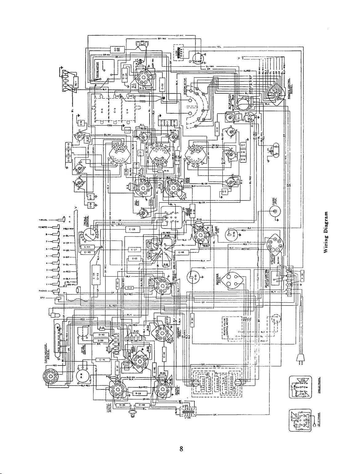
Wiring
Diagram

REPLACEMENT
PARTS
Use
genuine
Stromberg-Carlson
parts.
It
will
be
to
your
advantage.
They
are
made
for
use
in
Stromberg-Carlson
receivers.
The
specifications
are
correct
and
the
same
high
quality
material
and
workmanship
is
used
as
in
the
whole
radio
receiver.
Don’t
ruin
a
good
receiver
with
an
inferior
part.
Capacitors
Piece
Number
Circuit
Designation
24559
C-22,42,
57
24994
C-32,49,26
25149
C-33,43,27
25150
C-39
....
25487
C-34,59
26778
C-21
....
27108
C-18,
20,24,
25,
26,
27,
30,
31
27305
C-58
....
27646
C-44,48
28594
C-40
....
30116
C-23
....
30251
C-17
....
30252
C-18
...
30322
C-2,
41,
45,
46,
47,
63
27143
C-10,11,12
30253
C7,
8,
9,13,14,15
27336
C-55
....
27622
C-56
....
30231
C-51,52
30232
C-53,54
30282
C-4,5,6
30539
C-60,61
Part
100
mmf.
.05
mf.
.01
mf.
.02
mf.
.001
mf.
.005
mf.
2—.05
mfs.
50
mmf.
....
.02
mf.
....
.015
mf.
.003
mf.
.
.
..
.001
mf.
.002
mf.
....
.005
mf.
Aligning
Capacitor
Aligning
Capacitor
1—16
mf.
500
V
(Electrolytic)
1—16
mf.
500
V
(Electrolytic)
1—15
mf.
350
V
(Electrolytic)
1—15
mf.
300
V
(Electrolytic)
1—8
mf.
350
V
(Electrolytic)
1—
20
mf.
35
V
(Electrolytic)
Tuning
Capacitor
(3
gang)
2—
20
mfs.
Electrolytic
120
V
A.C.
Coils,
Transformers
and
Speaker
30143
L-5,6
...
Antenna
Coil
C
Band
.
30144
L-16,17
Oscillator
Coil
B
Band
30145
L-18,19
Oscillator
Coil
C
Band
30146
L-12,13
R.
F.
Coil
C
Band
30147
L-3,
4,10,11
Antenna
and
R.
F.
Coil
B
Band
30148
L-8,9
...
R.
F.
Coil
A
Band
30149
L-2,3
...
Antenna
Coil
A
Band
.
30150
L-14,15,
C-16
Oscillator
Coil
A
Band
30233
L-29
....
Choke
Assembly
30332
L-7,
35
R.
F.
Choke
....
30238
L-l,
C-l
.
.
.
Wave
Trap
....
30229
L-30
to
L-34
inc.
Power
Transformer
50/60
Cycles
30230
L-30
to
L-34
inc.
Power
Transformer
25/60
Cycles
30242
L-20,
21,
22,
C-28,29
1st
I.
F.
Transformer
.
30245
L-23,
24,
C-35,
36
2nd
I.
F.
Transformer
30247
L-25,
26
Output
Transformer
.
27504
Speaker
26250
.
Controls
and
Knobs
Cone
for
Speaker
27313
Fidelity
and
Tone
Control
.
30236
Range
Switch
30249
R-18
.
.
.
.
Volume
Control
30279
Switch
Assembly
P.
B.
Key
30250
Bass
Switch
....
30327
Set-up
Switch
....
27800
Small
Plain
Knob
27801
Knob
with
Arrow
27628
Felt
Washer
for
Knobs
9

REPLACEMENT
PARTS—Continued
Piece
Number
Circuit
Designation
Part
Resistors
26325
R-37
.
220
Ohms—Type
E
26328
R-3,
7,12
.
390
Ohms—Type
E
26333
R-5,10
1000
Ohms—Type
E
26345
R-8
.
10,000
Ohms—Type
E
26350
R-17
.
27,000
Ohms—Type
E
26353
R-6,9
47,000
Ohms—Type
E
26355
R-4
.
68,000
Ohms—Type
E
26356
R-13
.
82,000
Ohms—Type
E
26357
R-l,
2,
25
.
.1
Megohm—Type
E
.
26359
R-23,
24
.15
Megohm—Type
E
.
26362
R-21,
26,
27,
32
.27
Megohm—TypeE
.
26364
R-16
.
.39
Megohm—Type
E
.
26367
R-31
.
.68
Megohm—Type
E
.
26369
R-19,38
1
Megohm—Type
E
26373
R-14
.
2.2
Megohm—Type
E
.
26381
R-20,22
10
Megohm—Type
E
.
26775
R-29
.
20,000
Ohms—Type
F
26776
R-30
.
12,000
Ohms—Type
F
28956
R-28
.
200
Ohms
IRC
....
30235
R-33,
34,
35,
36
Voltage
Divider
30605
R-39
.
Miscellaneous
Parts
170
Ohm—Type
F
26122
Antenna
and
Ground
Terminal
Strip
26287
Pilot
Lamp
....
26678
3-Prong
Socket
...
29786
Pilot
Lamp
Socket
Assembly
30151
8-Prong
Socket
....
30152
7-Prong
Socket
....
30153
4-Prong
Socket
.
30223
11-Prong
Socket
28652
Power
Supply
Cord
29162
Spring
29628
Spring
for
Drive
Cord
30065
Dial.
30169
Station
Call
Letters
30172
Dial
Escutcheon
30176
Electric
Tuning
Escutcheon
30341
Screw
for
Mtg.
Dial
Escutcheon
.
30345
Screw
for
Mtg.
Electric
Tuning
Escutcheon
30224
Phono.
Plug
....
30225
Phono.
Guard
....
30226
Phono.
Jack
....
30256
Shaft
for
Motor
Drive
(Vol.
Control)
30262
Motor
for
Dial
Drive
.
30265
Pulley
.....
30934
Set
Screws
for
Pulley
Assembly
.
30276
Dial
Pointer
....
30286
Commutator
Assembly
30295
Brush
Holder
....
30385
Brush
(Inside
Slot)
30297
Brush
(Outside
Slot)
30261
Tuning
Indicator
Cable
30299
Cable
(Plug
to
Push
Buttons)
30292
RC-1
.
Compensator
Unit
30275
Tools
and
Accessories
Bronze
Drive
Cord
Assembly
SD-29
Phillips
No.
1
Screwdriver
.
24608
Aligning
Tool
....
28601
Cabinet
Polish
(Pt.
Can)
26962
Furniture
Touch-Up
Kit
28303
Headphone
Package
Assembly
10

Showing
Adjustable
Station
Brushes
and
Set
Up
Switch.
This manual suits for next models
2
Table of contents
Other Stromberg-Carlson Receiver manuals


