manuals.online logo
Brands
  1. Home
  2. •
  3. Brands
  4. •
  5. Philco
  6. •
  7. Receiver
  8. •
  9. Philco 41 User manual

Philco 41 User manual

Other Philco Receiver manuals

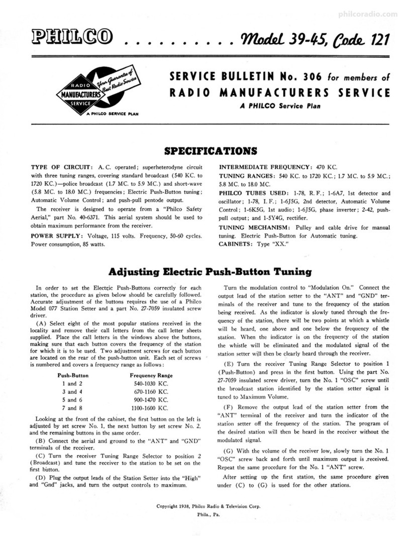
Philco 121 Reference manual

Philco

Philco 121 Reference manual

Philco 38 User manual

Philco

Philco 38 User manual

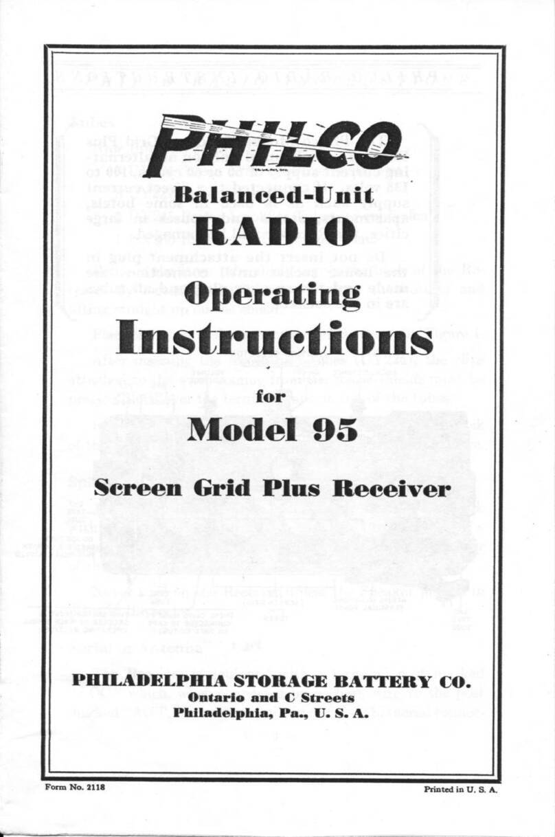
Philco 95 User manual

Philco

Philco 95 User manual

Philco 37-61 Reference manual

Philco

Philco 37-61 Reference manual

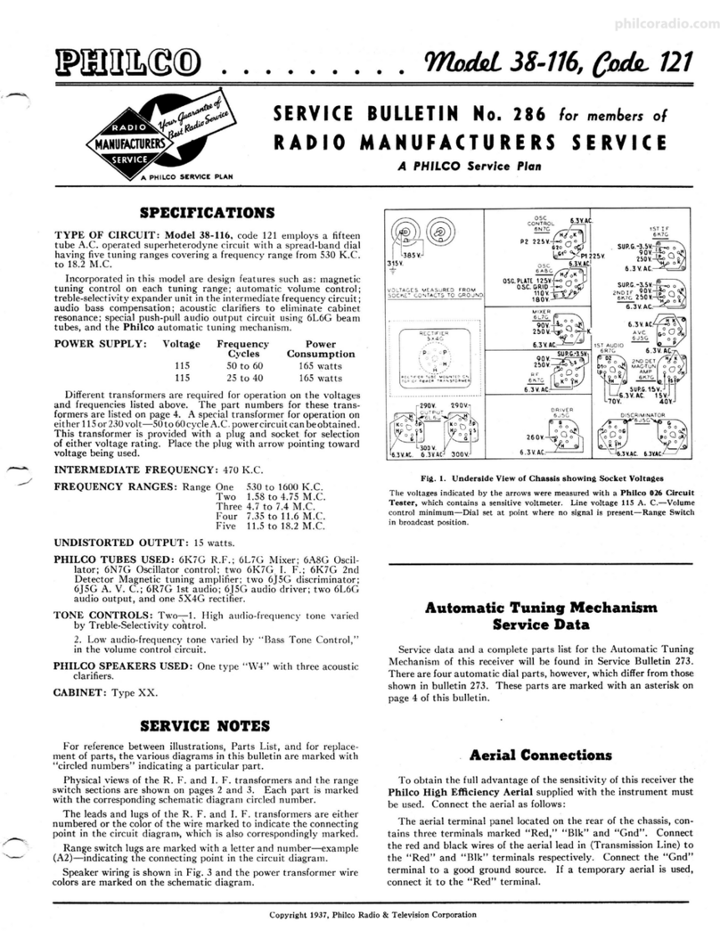
Philco 38-116 Reference manual

Philco

Philco 38-116 Reference manual

Philco 76 User manual

Philco

Philco 76 User manual

Philco 50 User manual

Philco

Philco 50 User manual

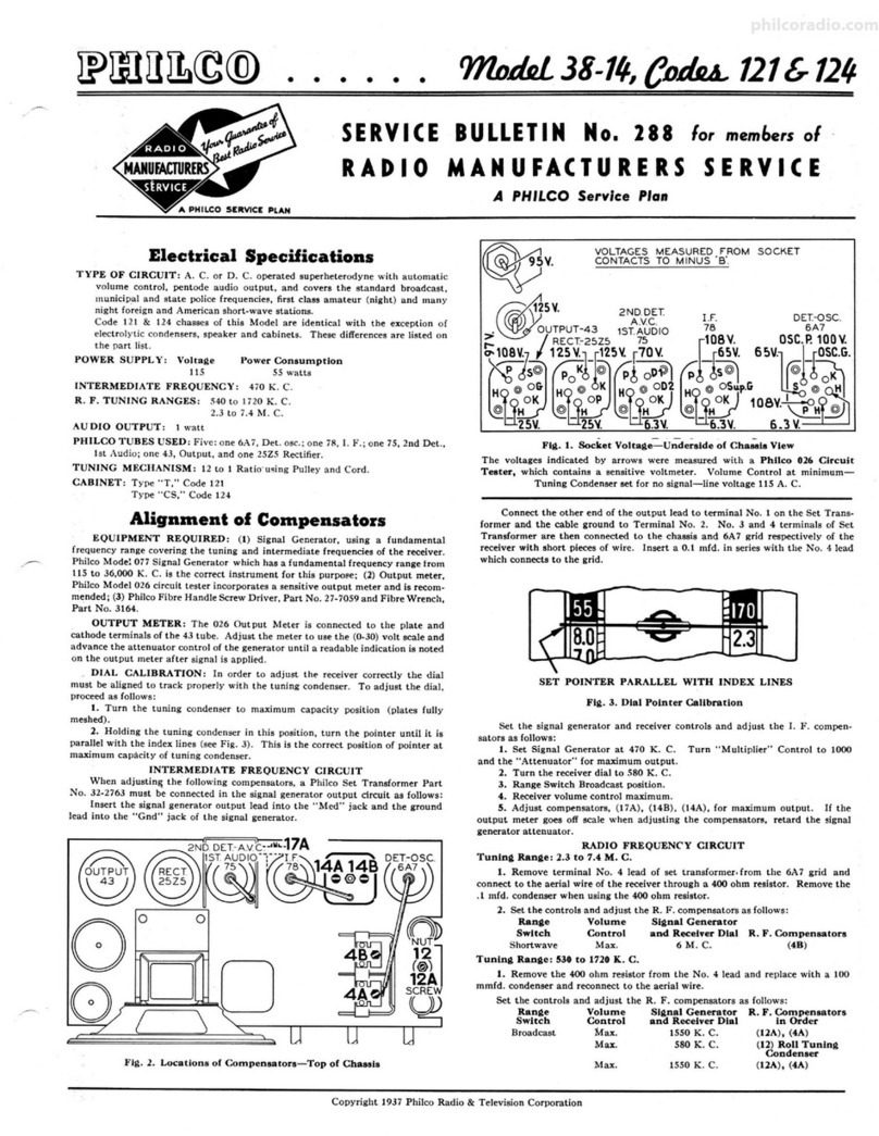
Philco 38-14 Reference manual

Philco

Philco 38-14 Reference manual

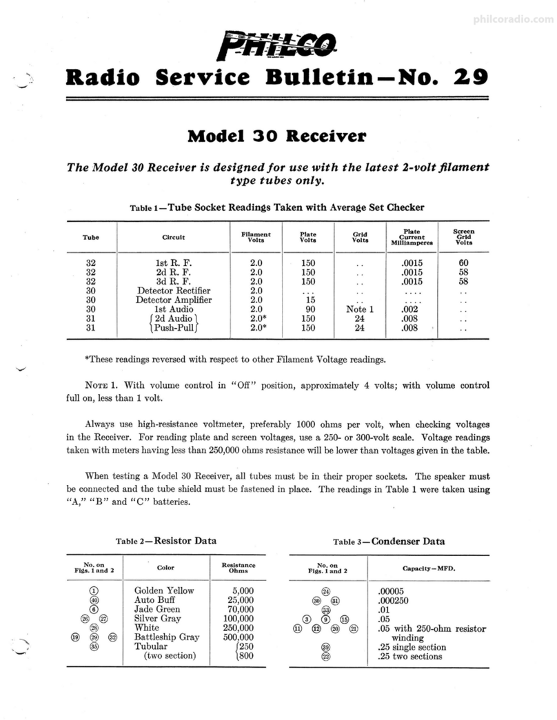
Philco 30 User manual

Philco

Philco 30 User manual

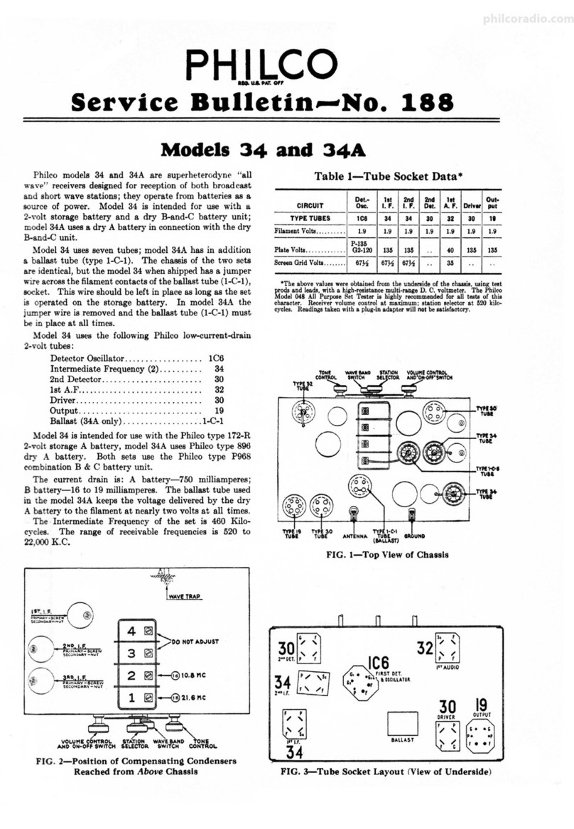
Philco 34 User manual

Philco

Philco 34 User manual

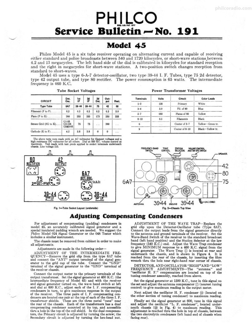
Philco 45 User manual

Philco

Philco 45 User manual

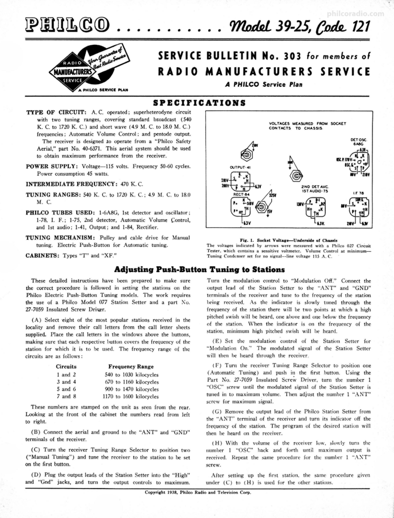
Philco 39-25 Reference manual

Philco

Philco 39-25 Reference manual

Philco 39-85 Reference manual

Philco

Philco 39-85 Reference manual

Popular Receiver manuals by other brands

Televes ZAS HD SAT user manual

Televes

Televes ZAS HD SAT user manual

Realistic DX-75 Operating and service instructions

Realistic

Realistic DX-75 Operating and service instructions

Saris 4620 Assembly instructions

Saris

Saris 4620 Assembly instructions

Mini DTR 206C PVR user manual

Mini

Mini DTR 206C PVR user manual

RF Elements TwistPort manual

RF Elements

RF Elements TwistPort manual

Denon DN-200WS user guide

Denon

Denon DN-200WS user guide

Yamaha RX-V467 owner's manual

Yamaha

Yamaha RX-V467 owner's manual

Russound SaphIR 858 instruction manual

Russound

Russound SaphIR 858 instruction manual

Quasonix RDMS Firmware update procedure

Quasonix

Quasonix RDMS Firmware update procedure

Pioneer XV-HTD1 Service manual

Pioneer

Pioneer XV-HTD1 Service manual

ATZ HDMI-V2-44HE150 manual

ATZ

ATZ HDMI-V2-44HE150 manual

Sony XNV-770BT MyTomTom Specifications

Sony

Sony XNV-770BT MyTomTom Specifications

Grundig STR 7122 TWIN Service manual

Grundig

Grundig STR 7122 TWIN Service manual

Creative Blaster Modem user guide

Creative

Creative Blaster Modem user guide

Panduit ATLONA AT-OME-RX11 installation guide

Panduit

Panduit ATLONA AT-OME-RX11 installation guide

VOLTCRAFT UTPS-40 operating instructions

VOLTCRAFT

VOLTCRAFT UTPS-40 operating instructions

JVC KW-ADV794 instructions

JVC

JVC KW-ADV794 instructions

Litelink VT-1001 operating instructions

Litelink

Litelink VT-1001 operating instructions

manuals.online logo
manuals.online logoBrands
  • About & Mission
  • Contact us
  • Privacy Policy
  • Terms and Conditions

Copyright 2025 Manuals.Online. All Rights Reserved.

Model 41 Receiver
The Model 41 Receiver is for use on 100-130 volts Direct Current only
Table 1-TUBE SOCKET READINGS
Line Voltage 115
Screen Control Plate
Tube Circuit Fllament Plate Grid Grid Mila
24 1 R. F. 2.1 100 75 .4 · 2.7
24 2 R. F. 2.1 100 75 .4 2.7
24 Detector 2.1 45 15 1.8
27 1 A. F. 2.4 87 .2 2.7
71-A 2A. F. 5 85 13 15
Readings must be taken with volume control
on full.
Always use high-resistance voltmeter, pref-
erably 1000 ohms per volt, when checking volt-
ages in the Receiver. For reading plate and screen
voltages, use a 250- or 300-volt scale. Voltage
readings taken . with meters having less than
250,000 ohms resistance will be lower than
voltages given in the table.
Table 3-CONDENSER CAPACITIES
(Other than Filter Condenser)
No. on
Flaa. land 3
®
@-@-@-@
®-@
®
MFD. Capacity .
.01
.05
.25
.0005
Table 2-RESISTOR VALUES
No.on
Flaa. land 3
@-@
@
@-@
0-@
@
@-®
@-@
@
®
@
Terminals
. . . . . . . .
. ·{1-2 . . . . .
2-3 . . . . .
(Note: 20-inch- External)
Ohms
Resistance
5,000
13,000
25,000
33,000
70,000
100,000
500,000
250
4
. 2
53
@ Filter Condenser Part No. 4067
5
FIil, 1
philcoradio.com
+
71A
GND.
;----- - - _'T' _______ ..,. ______ -- -- -r - -- - --- - - - - -·- -- -,:
I I I 1
, 4 2.// ~.lt h ?=\ l= 'Z-7
@
®- 0-@
'r-B
®'-
G @-~ }-®
C ....;..,
G
71A I I I i
-!., I I j
UV A~-~-- T ...:.-, ....:..., 1
A B . F
~
INDICATES CHASSIS ©-~ ~-© ."®
.---------,.--~---,.....-----)G
~L-----)U
1..AJJ. )V
®+. I @" )p
@- )S
.) F
p
:+@
s
A B C
3
SPEAKER PLUG AND SOCKET TERMINALS
ARE INDICATED -o-
R
RESISTOR@IS MOUNTED AT BOTTOM OF CABINET
Fi~ . 2
I
•
N
f
a.
0
fl)
ft
~
~
.,
i
,.,
Et
...
5·
f
...
•
philcoradio.com
2ND A.F.PUSH-PULL
SOCKETS
TONE
CONTROL
DETECTOR
SOCKET
STATION
SELECTOR
2No.R.F.
SOCKET
Fla.3
B FlLTER
CONDENSER
RESISTOR
PLUG SOCKET
1
•
~
•
,a
~
!
fl)
ft
~
"'"
◄
!'
.. illi/.H
"
ft '11
1111'1
&
ft
...
Ii
i
"'
philcoradio.com
P-NNiSO
Page4 Radio Service Bulletin No.16
GENERAL
This Receiver is for use on 100 to 130 volts direct current. It must not be connected to an alternat-
ing current line.
The resistor plug must be placed in the socket at the rear right-hand corner of the base. This socket
is used for an 80 rectifier tube in some of the A.C. models. No rectifier is required with this Receiver,
although if a tube is placed in this socket no damage will be done.
The field coil of the speaker used with this Receiver is of low resistance. · It is not the same as the
field coil used with the A.C. Electric Receiver. If by mistake, a speaker from an A.C. Electric Receiver
is.plugged into the D.C. Receiver, no damage will be done, but only an extremely weak, distorted signal
will be obtained. If a speaker from a D.C. Electric Receiver is plugged into an A.C. Receiver, again no
damage will be done, but the reception will be weak and distorted.
COMPENSATING
Always use an oscillator signal when adjusting compensating ()ondensers. With the Receiver set
up for operation, adjust the oscillator and Receiver so the signal is tuned in between 120 and 140 on the
tuning scale. Have the Receiver volume control turned on full. Adjust the oscillator so that the received
signal is very weak. Using a fibre wrench turn down on the adjusting nut of the first compensating con-
. denser until it is quite tight. This purposely throws the first stage out of balance while adjusting the
second stage.
After tightening this first adjusting nut compensate the second condenser in the usual manner,
th~t is, tune the Receiver very carefully to the oscillator signal and adjust the compensating condenser
for the maximum signal. After this adjustment has been made, adjust the first compensating condenser
in the same manner. REPLACEMENT PARTS
No. on
Fill,8. l and 3 Description
CD Volume Control . .
@ First R. F. Transformer
® Tuning Condenser .
© Compensating Condenser
® Second R. F. Transformer
® By-Pass Condenser .
(j) Resistor . . . . .
® Compensating Condenser
® By-Pass Condenser .
@ Coupling Condenser . .
@ Third R. F. Transformer
@ By-Pass Condenser .
@ Resistor . . . .
@ Coupling Condenser . .
@ Fourth R. F. Transformer
@ By-Pass Condenser
@ ];wsistor . . .
@ By-Pass Condenser
@ Resistor
@) Resistor . .
® By-Pass Condenser
@ By-Pass Condenser
@ Resistor
@ Resistor
@ Resistor
@ Resistor . .
® By-Pass Condenser
@ Resistor . .
@ Tone Control . .
@ Input Transformer
@ On-Off Switch . .
@ Filter Condenser Block
@ Resistor
@ Resistor
Part No.
4094
3884-A
4069-E
3772-A
3884-B
3584-D
3525
3772-A
3557-A
3892-A
3884-C
3584-D
3525
3892-A
3884-C
3584-D
3526
3584-D
3656
3767
3774
3557:.A
3766
3542
3769
3767
3897-A
3769
4037-A
3872
3517
4067
4142
3656
No . on
Fias. land 3
@ Choke .
® Resistor
® Resistor
Description
@ Resistor . . . .
@ Output Transformer.
@ Voice Coil and Cone
@ Field Coil .
@ Pilot Lamp . . .
Resistor Conn. Plug .
Knobs (Large)
Knobs (Small)
Knobs (Switch)
Spring (Knob)
Grid Clip . . .
Grid Clip Insulator
Condenser Shield
Tube Shield . . . .
Cushion (Condenser Brace) .
Rubber Washer (Cond. Brace) .
Rubber Washer (Condenser)
Speaker Plug and Cable .
Rubber Washer (Furniture).
Pilot Insulator
Pilot Guard .
Condenser Brush . .
R. F. Transformer Shield
Bottom Plate . . . . .
Compensating Condenser Nut
Tuning Scale . .
Condenser Cable . .
Condenser Cable Spring
Pilot Lamp . . .
4-hole Tube Socket .
5-holc Tube Socket .
PHILADELPHIA STORAGE BATTERY COMPANY
Ontario and C Streets, Pblladelpbla, Pa.
Part No.
3422
3526
4057
4058
2848
2814-B
2799
3463
4071
3580-A
3579-A
3676-A
3305
4060
4061
4065
3878-A
3914
3915
3920
L-1056-A
3558
4054
4055
3748
3862
3406
3151
3794
3484
3012
3463
3423-A
3442-A
May, 1930 Form No. 2323 Printed in U. 8. A,
philcoradio.com