Strong Entertainment Lighting SEL10 Installation and operation manual

SEL10
Lamphead & Base Assembly
Operator’s Manual & Parts List
for Equipment Type MLS210
Rev. July 2001
a division of Ballantyne of Omaha, Inc.
4350 McKinley Street • Omaha, Nebraska 68112 USA
Tel 402/453-4444 • Fax 402/453-7238
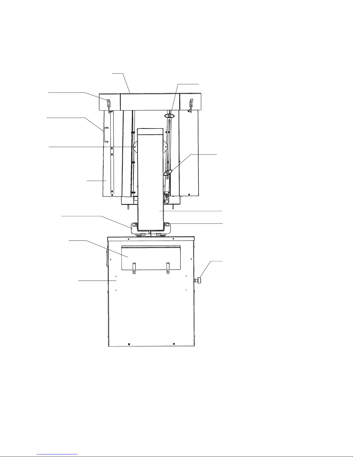
Lamphead Housing
Front Cowl Assembly This Knob used for
TRANSPORT ONLY.
Clamping Knob,
Projection Angle
Remove upper Knob after
transporting SEL10. Establish
Projection Angle and secure tilt
angle using lower Clamping
Knob only.
Locking Mechanism,
Horizontal Pan
Cover Plate,
Control Panel
Yoke Assembly
Base & Power
Supply Housing
SEL10 LAMPHEAD & BASE ASSEMBLY
Secured for Transport
Tie-Down Bracket
(1 of 4)
Cowl Clamp
(1 of 4)
Handle
(1 of 4)
Transport Support
Mechanism
Do Not Obstruct
Ventilation Openings
Yoke Retaining Screw
(1 of 2)

PREFACE
The SEL10 is a 10,000 watt xenon searchlight mounted on a rotating yoke. The angle and direction
of light projection are independently adjustable on a 360° horizontal arc and through 90° of vertical tilt,
and locks in the desired position. The base assembly is a weathertight enclosure containing the xenon
power supplies. The unit is mounted on a trailer and powered by a diesel engine-generator unit.
Continuous high output performance is assured by means of a coated, 30 inch precision electro-
formed, parabolic nickel reflector. The reflector is carefully positioned at the factory and requires no
operator adjustment. The light source is a 10,000 watt xenon bulb which can operate in any position
(vertical to horizontal) and maintains a constant color temperature of 5600° Kelvin. A squirrelcage blower
is mounted in the lamphead to provide continuous forced-air cooling while the bulb is in operation. The
bulb is warranted for 500 hours. It is recommended to replace the bulb upon expiration of the warranty.
Operator controls mounted to the instrument panel include a SYSTEM ON/OFF switch and a STRIKE
(“emergency ignite”) switch to bypass the autostrike circuit. A FOCUS switch controls an AC motor inside
the lamphead which moves the bulb inside the reflector to adjust focus. An hour meter, located adja-
cent to the switches, records the elapsed time of xenon bulb operation. A volt meter and ammeter
monitor xenon bulb operation.
Direct current for the xenon bulb is derived from two high reactance xenon power supplies mounted
in the base of the unit. All models are designed for 50/60 Hertz operation, and are available in varying AC
input types, depending upon the confuguration of the main power transformer. Check the Equipment
Data Plate to determine the exact AC requirement prior to installation.
Coarse and fine taps are easily set to regulate the DC current to the xenon lamphead. Some models
of these power supplies have the capability of overdriving the xenon bulb; carefully check the power require-
ments specified by the bulb manufacturer and do not exceed the maximum current stated.
The two power supplies, wired in parallel, produce the high open circuit ( “no load”) voltage
required for bulb ignition, and, after ignition, the filtered low voltage current to sustain operation. The
bridge rectifiers utilize silicon diodes as the power conversion elements. The diodes are mounted to
oversize heat sinks to disperse the heat generated by normal operatrion. Internally wired squirrelcage
blowers provide additional forced-air cooling of each power supply. Thermal switches act as safety
interlocks to shut down the power supplies and protect the rectifier diodes in case temperatures reach
excessive levels.
INSTALLATION
Check all equipment Data Plates and make certain that the generator unit conforms to the
input requirements of the main transformers of the xenon power supplies. Refer to the instructions fur-
nished separately for generator start-up procedures. Set generator output to 208/230 V.AC, 60 Hz. All
output connections to the xenon power supplies and lampheads are factory prewired.
Remove the (2) end panels from the base assembly to gain access to the tap terminal boards of
the xenon power supplies. Remove the upper clamping knob (“TRANSPORT ONLY”) from the projection
angle locking arm. Loosen the (2) set screws securing the yoke position and fold the hinged plate of the
transport support mechanism down. Loosen the projection angle clamping knob and lower the lamphead
to a horizontal position. Retighten the clamping knob to secure the lamphead. Release the (4) cowl
clamps and remove the front cowl assembly.
1
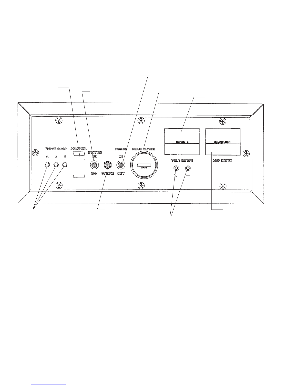
OPERATOR’S CONTROL PANEL
Indicator Lights,
Phase Detection
Circuit Breaker,
Auxilliary Power Toggle Switch,
POWER ON-OFF
Elapsed Time Meter
(HOURS)
Pushbutton Switch,
IGNITE (AutoStrike
Bypass)
Toggle Switch,
FOCUS IN-OUT
2
Volt Meter
Ammeter
Test Points,
DC Voltage

INSTRUCTIONS FOR REMOVING AND INSTALLING A TYPE “XT”
XENON BULB IN A SEL10 FIXTURE
NOTE
FAMILIARIZE YOURSELF WITH THE LOCATION AND IDENTIFICATION
OF THE COMPONENTS OF THIS SYSTEM AND ALSO THE NORMAL
OPERATION OF THE SYSTEM BEFORE ATTEMPTING ANY ADJUSTMENT
OR SERVICE.
NOTE
COMPLETELY READ THROUGH AND HAVE A GOOD UNDERSTANDING OF THE
PROCEDURES BEFORE ATTEMPTING TO SERVICE THIS SYSTEM. FAILURE TO
DO SO MAY RESULT IN FATAL INJURY OR EQUIPMENT DAMAGE.
NOTE
THE LAMPHEAD SHOULD BE LOCKED IN THE HORIZONTAL POSITION
DURING ANY SERVICE PROCEDURES.
WARNING
DISCONNECT POWER SOURCE BEFORE SERVICING THIS EQUIPMENT.
WARNING
A PROTECTIVE JACKET, FULL FACE SHIELD, AND PROTECTIVE GLOVES MUST
BE WORN AT ALL TIMES WHEN THE LAMPHEAD IS OPENED WITH A BULB
INSTALLED, OR WHEN HANDLING THE XENON BULBS. SERIOUS INJURY MAY
OCCUR IF PROPER SAFETY PRECAUTIONS ARE NOT OBSERVED.
READ ALL ENCLOSED INSTRUCTIONS AND INFORMATION SHEETS BEFORE
HANDLING THE BULB.
WARNING
NEVER OPERATE A FIXTURE WITH AN EXPOSED BULB! THERE IS AN EXTREME
DANGER OF SEVERE BURNS TO EXPOSED SKIN AND EYES FROM THE
ULTRAVIOLET LIGHT EMITTED FROM THE EXPOSED BULB. DAMAGE CAN
OCCUR IN AS LITTLE AS 30 SECONDS OF EXPOSURE. THERE IS ALSO
AN ADDITIONAL DANGER FROM FLYING QUARTZ IF AN
EXPOSED BULB EXPLODES!
EQUIPMENT REQUIRED
1.PROTECTIVESAFETYEQUIPMENTKIT
2. 7/16" END WRENCH OR SOCKET
3. ALLEN WRENCH 5/32"
3

ASSEMBLY PROCEDURE
WARNING
DO NOT REMOVE THE PROTECTIVE COVER FROM THE BULB UNTIL INSTRUCTED TO DO SO!
WARNING
DO EXERT ANY FORCE ON THE QUARTZ PORTION OF THE BULB AT ANY TIME!
NOTE
IF THE FRONT BULB HOLDER HAS NOT BEEN DISASSEMBLED, SEE THE LAST STEPS IN THE
APPROPRIATE DISASSEMBLY INSTRUCTIONS.
1. UNTIE THE CORD ON THE ANODE (+) END OF THE PROTECTIVE COVER. DO NOT REMOVE THE
COVER AT THIS TIME!
2. FASTEN FRONT BULB HOLDER TO THE BULB BY PLACING THE ANODE END (LARGE ELECTRODE)
OF THE BULB IN THE BULB HOLDER AND ALIGNING THE STUD ON THE END OF THE BULB
FERRULE WITH THE CHANNEL IN THE NOSE OF THE BULB HOLDER BODY. SLIDE THE BULB
COMPLETELY DOWN THE CHANNEL AS FAR AS IT WILL GO.
DISASSEMBLY PROCEDURE
PRIOR TO BULB INSTALLATION:
1. RELEASE THE (4) FASTENERS LOCATED AT THE SMALL SIDES OF THE COWL. PULL FORWARD
TO REMOVE THE COWL ASSEMBLY.
2. REMOVE THE (2) BRASS BOLTS CONNECTING THE SHORT LEADS TO THE FRONT BULB HOLDER
USING A 7/16" WRENCH.
3. REMOVE THE CENTER MOUNTING SCREW, WASHER, AND SPRING FROM THE SPIDER (SEE
FIGURE 4, ITEMS 2, 3, 4) USING A 5/32" ALLEN WRENCH WHILE SUPPORTING THE FRONT BULB
HOLDER SO THAT IT DOES NOT FALL WHEN THE SCREW IS REMOVED.
4. REMOVE THE BULB HOLDER FROM THE FIXTURE.
5. TO DISASSEMBLE THE FRONT BULB HOLDER, REMOVE THE (2) CLAMP RETAINING SCREWS
LOCATED ON THE SIDE OF THE LAMP SWIVEL HUB USING A 5/32" ALLEN WRENCH, AND REMOVE
THE CLAMP.
4

WARNING
DO NOT APPLY ANY PRESSURE ON THE BULB WHILE REASSEMBLING THE FRONT BULB HOLDER!
3. REPLACE THE CLAMP AND REINSTALL THE (2) CLAMP RETAINING SCREWS LOCATED ON THE
SIDE OF THE BULB SWIVEL HUB USING A 5/32" ALLEN WRENCH.
4. INSTALL THE BULB INTO THE FIXTURE BY CAREFULLY INSERTING THE CATHODE (-) END OF THE
BULB THROUGH THE OPENING IN THE REFLECTOR. DO NOT STRIKE THE SURFACE OF THE
REFLECTOR.
5. INSERT THE END OF THE BULB FERRULE INTO THE OPENING IN THE BULB LAMP HOLDER
RECEIVER BLOCK AND ALIGN THE THREADS BY TURNING THE BULB COUNTERCLOCKWISE
UNTIL THE BULB THREADS DROP INTO THE RECEIVER THREADS.
CAUTION
DO NOT OVERTIGHTEN THE BULB IN THE RECEIVER BLOCK AS THIS MAY CAUSE
THE BULB TO “FREEZE” IN THE RECEIVER BLOCK, MAKING IT DIFFICULT TO REMOVE.
TIGHTEN THE BULB JUST ENOUGH TO APPLY SPRING PRESSURE TO THE THREADS
BUT NOT SO MUCH AS TO BOTTOM OUT THE LAMP FERRULE COMPLETELY
AGAINST THE RECEIVER BLOCK.
6. GENTLY ROTATE THE BULB CLOCKWISE UNTIL RESISTANCE IS FELT.
7. AT THIS POINT, THE BULB SHOULD BE IN CONTACT WITH THE SPRING PLUNGER ASSEMBLIES.
GENTLY TURN THE BULB AN ADDITIONAL 1/16 - 1/8 OF A TURN TO LOAD THE THREADS WITH
THE SPRING PLUNGERS.
8. SECURE THE FRONT BULB HOLDER TO THE SPIDER WITH THE SHOULDER BOLT, SPRING, AND
WASHER THAT WAS REMOVED DURING DISASSEMBLY.
9. CONNECT THE (2) SHORT LEADS FROM THE SPIDER TO THE FRONT BULB HOLDER USING THE
TWO BRASS BOLTS AND WASHERS THAT WERE REMOVED DURING DISASSEMBLY.
NOTE
ANY TYPE OF ALCOHOL IS SUITABLE FOR CLEANING THE BULB EXCEPT FOR
ALCOHOL THAT HAS BEEN DENATURED USING PETROLEUM PRODUCTS SINCE
THE DENATURING AGENT WILL LEAVE A RESIDUE ON THE QUARTZ ENVELOPE.
10. REMOVE THE PROTECTIVE COVER FROM THE BULB AND CLEAN THE QUARTZ PORTION OF THE
BULB COMPLETELY WITH ALCOHOL.
11. THE INSTALLATION IS NOW COMPLETE. REPLACE THE FRONT COWL AND TEST THE BULB.
12. LOG THE HOUR METER READING AT INSTALLATION.
13. PERFORM THE OUTPUT POWER ADJUSTMENT PROCEDURES. THE 10000W-XT BULB IS
DESIGNED FOR OPERATION WITHIN THE FOLLOWING RANGE:
165-210 AMPERES
50-54 VOLTS DC
NOTE: OPERATION BELOW 165 AMPERES WILL NOT PROLONG BULB LIFE, BUT RATHER WILL
DEGRADE BULB IGNTION BY DAMAGING THE CATHODE TIP.
14. PERFORM THE FOCUS AND X-Y PROCEDURES.
5

DISASSEMBLY PROCEDURE
IF THERE IS A LAMP IS INSTALLED IN THE FIXTURE:
1. RELEASE THE (4) FASTENERS LOCATED AT THE SMALL SIDES OF THE COWL. PULL FORWARD
TO REMOVE THE COWLING.
CAUTION
DO NOT PLACE ANY FORCE ON THE LAMP WHILE REPLACING THE PROTECTIVE WRAPPER!
2. WRAP THE BULB SECURELY IN THE PROTECTIVE WRAPPER THAT THE BULB WAS ORIGINALLY
SHIPPED WITH.
3. REMOVE THE (2) BRASS BOLTS CONNECTING THE SHORT LEADS TO THE FRONT BULB HOLDER
USING A 7/16" WRENCH.
4. REMOVE THE CENTER MOUNTING SCREW, WASHER, AND SPRING (SEE FIGURE 4, ITEMS 2, 3, 4)
FROM THE SPIDER USING A 5/32" ALLEN WRENCH WHILE SUPPORTING THE FRONT BULB
HOLDER SO THAT THE BULB DOES NOT DROP WHEN THE MOUNTING SCREW IS REMOVED.
WARNING
DO NOT EXERT EXCESSIVE FORCE ON THE BULB WHILE UNSCREWING IT FROM
THE REAR BULB HOLDER! THE BULB SHOULD RELEASE FROM THE REAR BULB
HOLDER WITH A VERY LIGHT COUNTERCLOCKWISE ROTATION. IF THIS DOES
NOT HAPPEN, SEE THE PROCEDURE FOR REMOVING A “FROZEN” BULB.
5. REMOVE THE BULB BY LIGHTLY PUSHING BACK ON THE BULB TO MOVE THE REAR BULB
HOLDER TO ITS REAR MOST POSITION WHILE LIGHTLY TURNING THE BULB IN A COUNTER-
CLOCKWISE ROTATION. THE BULB WILL RELEASE FROM THE REAR BULB HOLDER IN
APPROXIMATELY 1½ COMPLETE TURNS.
6. REMOVE THE BULB WITH THE FRONT BULB HOLDER ATTACHED FROM THE FIXTURE. PLACE IT
ON A STABLE WORKING SURFACE FOR THE REMOVAL OF THE FRONT BULB HOLDER.
7. TO REMOVE THE FRONT BULB HOLDER FROM THE BULB, REMOVE THE (2) CLAMP RETAINING
SCREWS LOCATED ON THE SIDE OF THE BULB SWIVEL HUB USING A 5/32" ALLEN WRENCH AND
REMOVE THE CLAMP.
8. REMOVE THE BULB HOLDER FROM THE BULB AND PLACE THE BULB INTO ITS SHIPPING
CONTAINER FOR SAFEKEEPING. RESECURE THE PROTECTIVE WRAPPER IF NECESSARY.
REMOVING A “FROZEN” BULB
1. REPLACE THE FRONT BULB HOLDER RETAINING BOLT TO SUPPORT THE FRONT OF THE BULB
WHILE FREEING THE BULB FROM THE REAR BULB HOLDER.
DO EXERT ANY FORCE ON THE QUARTZ PORTIONS OF THE BULB
WHILE ATTEMPTING TO FREE IT FROM THE REAR LAMP HOLDER!
2. REACH THROUGH THE OPENING IN THE REAR OF THE REFLECTOR AND GRASP THE BULB’S
END CAP (THE REAR METAL FERRULE). WHILE LIGHTLY PUSHING THE BULB BACK INTO THE
RECEIVER BLOCK, TURN THE BULB IN A COUNTERCLOCKWISE DIRECTION UNTIL THE BULB
BEGINS TO ROTATE FREELY.
6

REMOVING A “FROZEN” BULB (CONTINUED)
3. ONCE THE BULB IS FREE, DO NOT YET REMOVE IT FROM THE REAR LAMP HOLDER.
4. RETURN TO STEP 5 OF THE PRECEDING SECTION.
OUTPUT POWER ADJUSTMENT PROCEDURES
NOTE
FAMILIARIZE YOURSELF WITH THE LOCATION AND IDENTIFICATION OF THE
COMPONENTS OF THIS SYSTEM AND ALSO THE NORMAL OPERATION
OF THE SYSTEM BEFORE ATTEMPTING ANY ADJUSTMENT OR SERVICE.
NOTE
COMPLETELY READ THROUGH AND HAVE A GOOD UNDERSTANDING OF
THE PROCEDURES BEFORE ATTEMPTING TO SERVICE THIS SYSTEM.
FAILURE TO DO SO MAY RESULT IN FATAL INJURY OR EQUIPMENT DAMAGE.
WARNING
DISCONNECT POWER SOURCE BEFORE SERVICING THIS EQUIPMENT.
EQUIPMENT REQUIRED
1. SCREWDRIVER, Flat Blade, Large
2. SCREWDRIVER, #2 Phillips
ADJUSTMENT INSTRUCTIONS
1. Remove lower access covers from the ends of the base enclosure by removing the (6) screws
along the sides of each panel with a Phillips screwdriver.
2. Note the location and settings of the power supply adjustment taps.
7

ADJUSTMENT INSTRUCTIONS (continued)
3. Ignite the xenon bulb and check the current. Allow (30) seconds for the current to stabilize and
provide an accurate reading. A new 10000W-XT bulb should be first operated at the nominal current
level of 180-185 amperes. If the current is not within the desired range, extinguish the bulb. It will be
necessary to increase or decrease the DC output.
4. Fine adjustment of the DC current is made to the NUMBERED taps found on the upper three terminal
blocks (TB4, TB5, TB6). Fine taps are numbered 1-2-3-4, with “1” providing the lowest output, increasing
to “4,” yielding the highest output. A “fine” tap adjustment raises or lowers the current approximately four
amperes. The three fine tap terminal blocks are interconnected by means of a three-lead jumper wire
assembly attached to like-numbered terminals.
•To increase the DC output, move the jumper wire assembly to tap the next (3) higher numbered termi-
nals, for example, move from terminals “2” to terminals “3.” ALL TAPS MUST BE ON THE SAME NUMBERED
POSITION (1-1-1, 2-2-2, 3-3-3, or 4-4-4). If the DC output is still too low when terminals “4” are intercon-
nected, see the following instructions for adjusting “coarse” taps.
•To decrease the DC output, move the jumper wire assembly to tap the next (3) lower numbered
terminals, for example, move from terminals “3” to terminals “2.” ALL TAPS MUST BE ON THE SAME
NUMBERED POSITION (1-1-1, 2-2-2, 3-3-3, or 4-4-4). If the DC output is still too high when terminals “1” are
interconnected, see the following instructions for adjusting “coarse” taps.
5. Coarse adjustment of the DC current is made to the LETTERED taps found on the lower three terminal blocks
(TB1, TB2, TB3). Coarse taps are lettered W-X-Y-Z, with “W” providing the lowest output, increasing to “Z” at
the highest output. The coarse tap terminals connect to contactor terminals T1, T2, and T3. The (3) contactor
leads must connect to the same lettered step (W-W-W, etc.). A “coarse” tap adjustment raises or lowers the
current approximately twelve amperes.
•To increase the coarse DC output, move each of the contactor leads to tap the next higher lettered
terminals, for example, move from terminals “W” to terminals “X.” ALL TAPS MUST BE ON THE SAME
LETTERED POSITION (W-W-W, X-X-X, Y-Y-Y, or Z-Z-Z). Place the fine tap jumper on 1-1-1. Ignite the lamp,
check the output, and increase the fine tap setting as required.
•To decrease the coarse DC output, move each of the contactor leads to tap the next lower lettered
terminals, for example, move from terminals “Y” to terminals “X.” ALL TAPS MUST BE ON THE SAME
LETTERED POSITION (W-W-W, X-X-X, Y-Y-Y, or Z-Z-Z). Place the fine tap jumper on 1-1-1. Ignite the lamp,
check the output, and increase the fine tap setting as required.
NOTE: Balance power supply output; set power supplies at or near the same output setting, i.e.:
Power Supply “A” X-X-X, 4-4-4 (or as required)
Power Supply “B” Y-Y-Y, 1-1-1 (or as required)
6. Check the voltmeter and read the arc voltage. The voltage should read between 50 and 54 volts
DC. If the actual measured voltage is not in this range, consult your bulb supplier immediately.
7. Inspect tap connections to verify that the terminal is clamping the copper conductor, not the
insulation. Make certain all terminal clamping screws are tight.
8. Whenever making a coarse adjustment, again check the output current and make certain the cur-
rent is within the desired range. A fine tap re-adjustment is frequently required after changing coarse
taps.
9. After prolonged operation, the light output of the xenon bulb will decrease. This is a normal factor of
bulb aging, and can be compensated by raising the DC output of the xenon power supplies. If the
bulb was first operated at “nominal” current, the power supply output can gradually be increased
to, but not in excess of, the maximum current specified by the bulb manufacturer (210 A.). Increase
the current as instructed above. Decrease the power supply output to its former “nominal” current
level (180 A.) upon the installation of a new replacement bulb.
8

FOCUS AND X-Y ADJUSTMENT INSTRUCTIONS
FOR SYSTEMS w/ ELECTRIC FOCUS
NOTE
FAMILIARIZE YOURSELF WITH THE LOCATION AND IDENTIFICATION OF THE
COMPONENTS OF THIS SYSTEM AND ALSO THE NORMAL OPERATION OF THE
SYSTEM BEFORE ATTEMPTING ANY ADJUSTMENT OR SERVICE.
NOTE
COMPLETELY READ THROUGH AND HAVE A GOOD UNDERSTANDING OF THE
PROCEDURES BEFORE ATTEMPTING TO SERVICE THIS SYSTEM. FAILURE TO DO
SO MAY RESULT IN FATAL INJURY OR EQUIPMENT DAMAGE.
EQUIPMENT REQUIRED
1. ALLEN WRENCH 5/32"
2. #5 WELDERS GLASSES OR VERY DARK SUNGLASSES
WARNING
THE SEL10 SYSTEMS PROJECT A VERY INTENSE BEAM OF FULL-SPECTRUM LIGHT.
THE USE OF DARK GLASSES WHILE ADJUSTING THE BEAM PARAMETERS ON A
LIGHT-COLORED REFLECTIVE SURFACE AT A CLOSE DISTANCE IS MANDATORY.
WARNING
NEVER LOOK DIRECTLY INTO A LIGHTED FIXTURE'S LIGHT SOURCE.
ADJUSTMENT INSTRUCTIONS
1. Loosen the positioning fasteners and point the lamphead toward a wall, ceiling, or other flat
surface at least 10 feet away.
2. Locate the focus switch located on the control panel on the back of the lamphead housing.
3. Remove the front cowl and locate the X & Y adjustment holes located on the lower small sides of
the fixture at the ends of the front spider arms.
WARNING
SEL10 SYSTEMS PROJECT A VERY INTENSE BEAM OF FULL-SPECTRUM LIGHT.
CAUTION MUST BE TAKEN WHEN POINTING THE BEAM AT AN OBJECT AT A
DISTANCE OF LESS THAN 100 FEET WITH THE FOCUS SET FOR A CONVERGING
BEAM. COMBUSTIBLE OBJECTS AND OBJECTS WITH A DARK COLOR MAY UNEXPECTEDLY
IGNITE IF CARE IS NOT TAKEN IN THE FOCUSING AND POSITIONING OF THE BEAM.
4. Energize the fixture and ignite the lamp. A new xenon bulb should be drawing 180-185 amperes.
5. Adjust the focus by moving the focus switch up or down to produce a diverging beam pattern
with 2 or 3 clearly defined rings of light with or without an off-center “hot” spot.
6. Adjust the X & Y adjustment screws using a 5/32" allen wrench to move the inner rings of light to
create concentric rings with the “hot” spot at the center of the light field. Turning the adjustment
screw clockwise will move the rings toward that adjustment axis and turning the screw
counterclockwise will move the rings away from that adjustment axis.
9

XENON BULB MAINTENANCE
Allow the blowers to operate for at least (15) minutes after extinguishing the arc. This measure is
required by the bulb manufacturer to comply with bulb warranty conditions.
In order to insure maximum bulb life, the following procedures should be followed every 75-100 hours of
operation.
BULB ROTATION
If the fixture is used in a position other than pointed within 15% of vertical, the bulb should be rotated
1/3 of a turn to insure even deposition of the vaporized tungsten generated by the arc inside the bulb.
ADJUSTMENTPROCEDURES
1. Refer to the instructions for removal and installation of the bulb, noting all warnings.
2. Follow the disassembly procedure for a fixture with the bulb installed steps 1 thru 5.
3. When rotating the bulb for removal, continue LIGHTLY pressing rearward on the bulb. The threads
of the bulb will ride out of their current leads and drop into the next set of threads in the receiver
block. When this happens, you will feel the bulb drop down into the receiver block.
4. Immediately stop turning the bulb and reverse direction to screw the bulb in at the new
orientation.
5. Complete reinstalling the bulb per the bulb installation procedure.
POWER LEVEL ADJUSTMENT
Check the output power level of the system and readjust as necessary. A temporary current increase,
not exceeding 210 amperes, may enhance bulb ignition at its new position following rotation. After
ten to twelve hours of operation at the increased current, the arc will re-establish, and current may be
returned to the previous level.
Output may be increased to maintain light output as the bulb ages, but output must remain below
210 amperes. SEE POWER ADJUSTMENT PROCEDURES preceding.
FOCUS AND X-Y ADJUSTMENT INSTRUCTIONS (continued)
7. Readjust the focus switch to set the desired beam spread.
8. Replace the front cowl; reposition the lamphead and resecure the position locking fasteners.
10
TRANSPORTING THE SEL 10
It is recommended to remove the xenon bulbs before moving the SEL10. While there is little explosion
danger in moving the units with properly cooled bulbs and all lamphead covers in place, the bulb
manufacturer may not honor warranty claims on bulbs broken during transport. Under no
circumstances should the units be moved until the bulbs have cooled to ambient temperatures.
See the illustration facing Page 1 for the recommended method of securing the SEL10 for transport.
Raise the lamphead to the full vertical position and replace the upper clamping knob as shown.
Rotate the lamphead to align the yoke with the transport support mechanism and raise the hinged
plate. Secure the yoke in position using the (2) headless set screws. Tie-down brackets mounted to the
upright members of the yoke provide additional points to secure the lamphead if desired.
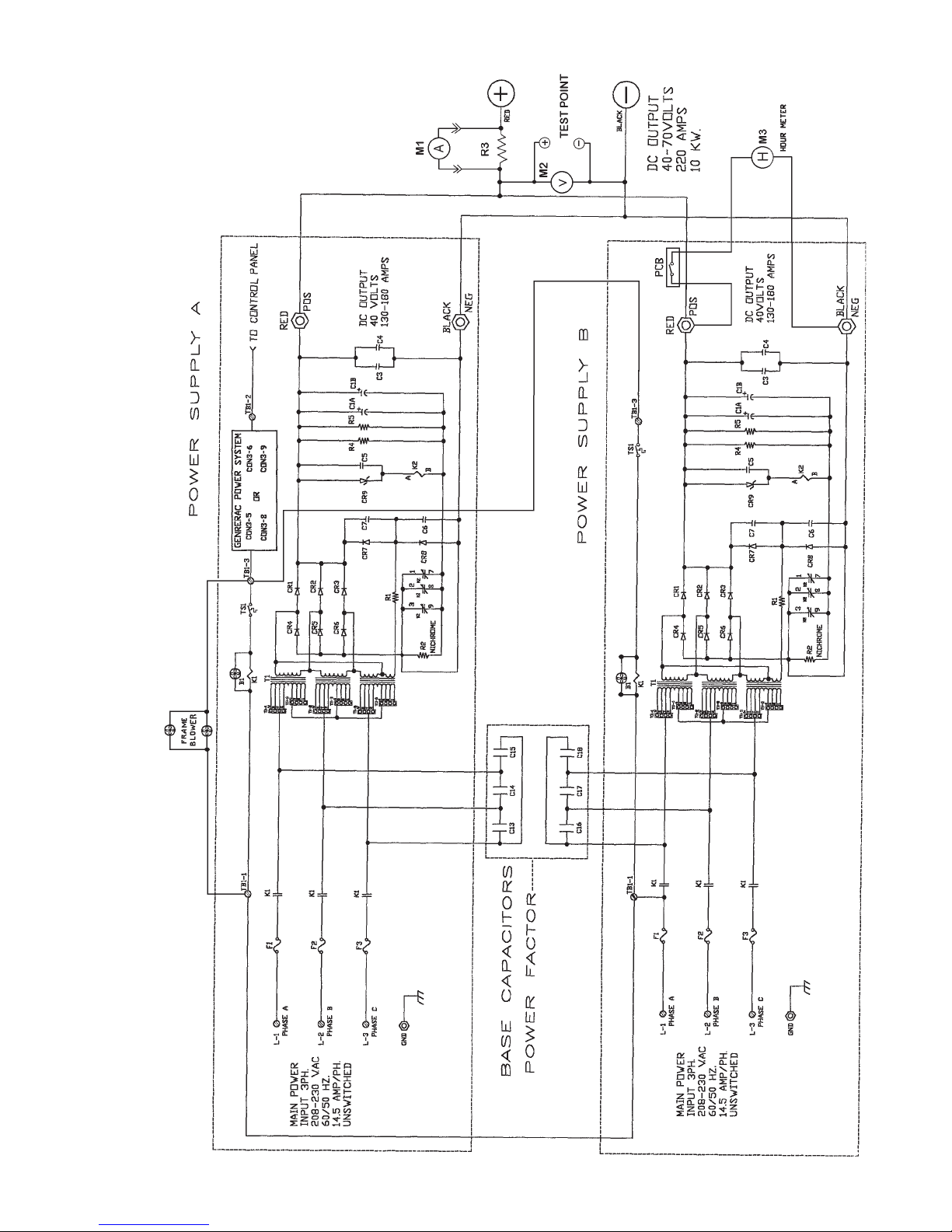
WIRING DIAGRAM
1 of 3
11
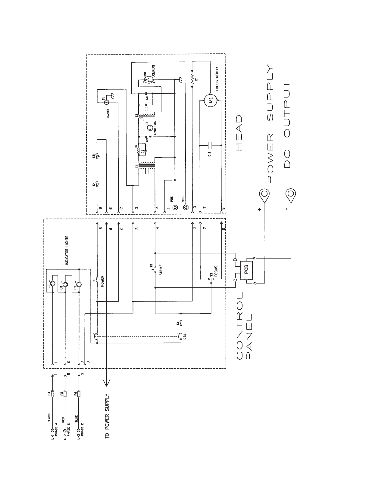
WIRING DIAGRAM
2 of 3
12

PARTS LIST, CONTROL PANEL and POWER SUPPLIES A & B (Diagram 1 of 2)
Ref.
Desig. Part No. Description
B1 81-33026 Blower
C1A,B 61-08027 Capacitor, 5400 µf, 200 V.
C3,4 81-08005 Capacitor, .33 µf
C5 81-08029 Capacitor,.01 µf, 600 V.
C6,7 81-08025 Capacitor, .005 µf, 800 V.
C13-18 31-08134 Capacitor, 4 µf, 370 V.AC
CR1-3 81-47004 Forward Diode, Rectifier; 100 A. 300 V.
CR4-6 81-47001 Reverse Diode, Rectifier; 100 A. 300 V.
CR7,8 81-47006 Boost Diode, 3 A. 600 V.
CR9 81-17002 Zener Diode, 36 V. 5 W. (1N5365B)
F1-3 31-21038 Fuse, 30 A. 250 V.
K1 81-14001 Contactor
K2 81-45016 Relay, 120 V.AC Coil
M1 31-32006 Ammeter, 0-300 A.DC
M2 31-32007 Volt Meter, 0-100 V.DC
- 31-98160 Test Point Socket, Black
- 31-98162 Test Point Socket, Red
M3 31-32004 Elapsed Time Meter*
PCB 32-70140 Printed Circuit Board, Current Detector for M3
R1 81-46026 Resistor, 100 Ohm, 100 W.
R2 92-70026 Nichrome Resistor
R3 81538000 Shunt, 300 A. 50 mV.
R4,5 81-46006 Bleeder Resistor, 2500 Ohm, 10 W.
T1 91-64011 Power Transformer
TS1 81-61010 Thermal Switch, Open at 210° F. (100° C.)
* Elapsed Time Meter may connect to either Power Supply A or B
PARTS LIST, CONTROL PANEL and LAMPHEAD (Diagram 2 of 2)
Ref.
Desig. Part No. Description
B1 32-70228 Squirrelcage Blower, 230 V.AC, 50/60 Hz.
C8 31-08009 Capacitor, .0047 µf
C9 31-08012 Capacitor, 2400 pf, 20 kV.
C10 79127000 Capacitor, .01 µf, 500 V.
C11 31-08011 Capacitor, .47 µf
C12 31-08134 Capacitor, 4 µf, 370 V.AC
CB1 32-61015 Circuit Breaker
DS1 31-30244 Xenon Bulb, 10 kW Type “XT”
E1 31-61009 Spark Plug (Air Gap)
F4-6 21-21002 Fuse, Type 3AG, 5 A.
L1-3 32-30076 Indicator Light, Amber (3 req’d.)
L4 31-71042 Choke, 16 AWG Magnet Wire
M1 32-70328 Bulb Focus Motor, 115 V.AC, 50/60 Hz. (with R1)
R1 11-46110 Resistor, 100 Ohm, 50 W. (incl. with M1)
PCB 32-00009 Igniter Printed Circuit Board Assembly (see Diagram 3 of 3)
S1 31-61048 Switch
S2 31-61011 Pushbutton Switch
S3 31-61049 Switch
S4 31-61078 Pressure Switch
S5 31-61134 Thermal Switch, Open at 325° F. (163° C.)
T2 31-64004 Transformer, High Voltage
T3 32-50230 Transformer, RF
13

14
WIRING DIAGRAM
3 of 3
Igniter Printed Circuit Board Assembly
Ref.
Desig. Part No. Description
C201 88263 Capacitor, .05 µf, 600 WVDC
C202 79127 Capacitor, .01 µf, 600 WVDC
C203 39156 Capacitor, 15 µf, 30/35 WVDC
C204 88249 Capacitor, .1 µf, 600 WVDC
CR201 85112 Diode, 2.5 A. 1000 PRV
CR202 85112 Diode, 2.5 A. 1000 PRV
CR203 85112 Diode, 2.5 A. 1000 PRV
K201 39154 Relay, P&B R10-E1-W2S800
- 39160 Relay Socket
- 39161 Relay Hold-Down Spring
Ref.
Desig. Part No. Description
R201 39157 Resistor, 1k Ohm, 12 Watt
R202 39158 Resistor, 100k Ohm, ½ Watt
R203 39159 Resistor, 200k Ohm, ½ Watt
U201 72185 Timer IC, Motorola MC11455P1
- 39164 IC Socket, (6) Pin
VR201 39211 Zener Diode, 1N5377A
VR202 39162 Zener Diode, 1N4742
- 39145 PC Board (less Components)
* 32-00009 PCB Assembly, Complete

POWER SUPPLY MAINTENANCE
VERY LITTLE MAINTENANCE is required to keep this power supply in good operating condition. Like
most lighting equipment, cleaning is the most important element.
WARNING
Turn off ALL primary AC power before making any
adjustments or performing service procedures. Allow several
minutes for the capacitors to drain stored energy.
Allow the power supply to cool to ambient temperature.
1. Remove all accumulated dust and dirt from the rectifier. Vacuum the heat sinks. Make
certain all air inlets and outlets are unobstructed.
2. Check all electrical connections for tightness. Clean, retighten, or replace any discolored
connections or terminals.
3. Apply a drop or two of SAE 20-weight oil to the squirrelcage blower motor bearings. It is neces-
sary to dismount the blowers from the chassis plate to access the oil holes.
POWER SUPPLY TROUBLESHOOTING
WARNING: Exercise extreme caution when
taking voltage measurements in a power
“ON” condition. Allow the capacitors (2)
minutes to discharge.
POWER LINE PROBLEMS
PRIMARY POWER (AC source) problems are most commonly (a) complete loss of AC power, or (b)
phase loss, in which one phase loses power.
a ) Check line safety switch (“ON”). Check fuses or breakers insupply line. Using an AC voltmeter,
measure input power at contactor terminals L1, L2, L3.
b ) When power is lost on one phase, the current ripple will increase and trip the AC line circuit
breaker (where supplied). To detect a lost phase, measure the AC voltage phase-to-phase at
contactor input terminals L1, L2, and L3.
PROBLEMS of this nature, once detected, are generally corrected at the power connection, or in the
generator unit.
BOOST CIRCUIT PROBLEMS
The boost circuit generates the high open circuit (“no load”) DC voltage which, in conjunction with the igniter
pulse, will ignite the xenon bulb. The open circuit voltage should measure at least 110 V.DC.
A tertiary winding on the main transformer (T1) supplies the source for the Boost Circuit. Three wires derive
from the T1 transformer; two are single conductors, and the third is a soldered pair. The Boost Circuit should
be connected only to the (2) single conductors. Filter capacitors C1A & C1B store energy and also contribute
to bulb ignition.
CONTROL CIRCUITRY
The main power transformer is energized by contactor K1, which is pulled by manual actuation of the
lamphead “ON” switch. All lamphouse interlock switches (air pressure & thermal overload) must also be closed
to complete the contactor circuit.
15

CONTROL CIRCUITRY (continued)
Any interruption of the control circuit will disable K1 and open the AC circuit to the rectifier. In addition to the
above lamphead interlock switches, thermal switch TS1, mounted to the rectifier heat sink, will open and
disable K1 if the temperature at the heat sinks exceeds 190° F. (88° C.). The TS1 switch will automatically re-
set when temperatures fall to safe levels.
POWER CONVERSION PROBLEMS
Rectification (AC to DC) is performed by bridge diodes CR1 - CR6. CR1, CR2, and CR3 are forward diodes,
and CR4, CR5, and CR6 are reverse diodes. The two types are not interchangeable.
An open diode will cause a pronounced flicker in the light output. Two or more open diodes will disable bulb
ignition. A shorted diode will trip the circuit breaker protecting the AC input line. See the following DIODE
TESTING & REPLACEMENT section.
Banked can capacitors C1A & C1B filter the rectified DC output. C1A and C1B capacitors also store energy to
contribute to the open circuit ignition discharge. A shorted capacitor can trip the AC circuit breaker.
Relay K2, in the presence of high DC open circuit voltage, will pull and place Resistor R2 in series with Capaci-
tors C1 and C2. This resistor limits the inrush surge and prolongs the discharge of C1A & C1B to promote bulb
ignition. If K2 relay fails, ignition may become erratic, and R2 may remain in circuit. With R2 in circuit, ripple
will increase to a level noticeable in light output, but not necessarily enough to trip the AC line circuit breaker.
DIODE TESTING & REPLACEMENT
1. Disconnect the diode from its circuit. Inspect for discoloration, oxidation, or loose crimp at lead junction.
2. A “shorted” diode will show low resistance in both directions. An “open” diode will have infinite
resistance in both directions. An Ohmmeter test is required.
3. a) Analog VOM: Select R x 1 Ohm scale. With meter leads connected in one direction, the
reading should be zero (or nearly so); reversing the meter leads should show very high resis-
tance. If the diode does not exhibit these characteristics, replace it. NOTE DIODE TYPE: forward
or reverse.
b) Digital VOM: Select “Diode Test.” With meter leads connected in one direction, the reading
should be “OL” (overload); reversing the meter leads should display approximately .4 volt. If the
diode does not exhibit these characteristics, replace it. NOTE DIODE TYPE: forward or reverse.
4. Carefully clean the area of the heat sink in which the diode mounts. Apply heat sink compound
(Radio Shack #276-1373 or equivalent) using a wood or plastic spatula or stick. A thin layer is
adequate.
WARNING
HEAT SINK COMPOUND IS HIGHLY CAUSTIC.
Do not apply with fingers; keep away from
eyes. Carefully follow ALL the instructions
printed on the package.
5. Install the new diode and tighten securely for maximum mechanical contact and electrical con-
duction. Clean and firmly secure the lead terminal to the buss.
16

POWER SUPPLY TROUBLESHOOTING
Contactor does not energize (no audible “click”).
1. Line safety switch open. Turn “ON.”
2. Circuit breaker or fuse in AC line open. Check AC source.
3. Faulty contactor coil or loose connection at coil terminals. Repair or replace.
Contactor pulls but lamphead igniter does not fire.
1. Faulty contactor contacts. With coil energized, check for continuity across the contacts from the
“L” side to the “T” side; repair or replace if defective.
2. Insufficient DC output. See INSTALLATION section; increase taps as required.
3. Faulty igniter.
4. Low open circuit voltage (less than 110 V.DC).
a) Check ceramic resistor R1; should be in circuit and measure 100 Ohms.
b) Check boost diodes CR7 and CR8. See preceding DIODE TESTING section.
c) Check filter capacitors C1A and C1B. Replace if defective.
5. Defective igniter printed circuit board assembly. Press STRIKE switch to override; do not hold STRIKE
switch longer thatn one second to prevent damage to high voltage transformer.
Bulb requires multiple ignition pulses to light.
1. Insufficient DC output. See INSTALLATION section; set taps as required.
2. Faulty K2 relay. Replace if defective.
3. Faulty or expired xenon bulb. Check for darkened envelope, worn electrodes; replace if re-
quired.
4. One or more faulty bridge diodes. See preceding DIODE TESTING section.
Bulb goes out during operation.
1. Excessive heat at rectifier heat sinks; thermal switch TS1 opening. Check for free air flow, blower(s)
operating at full speed. Check for loose connection.
2. Open lamphead thermal interlock switch.
3. Defective bulb. Check for scorched electrodes or discolored envelope.
Excessive flicker in light output.
1. Improper tap setting. All taps must be on same numbered or lettered step.
2. Faulty bridge diode. See preceding DIODE TESTING section.
3. Faulty xenon bulb. Check for cracked or sagging electrode(s).
4. Open filter capacitor C1A or C1B. Replace if defective.
Bridge diodes (CR1-6) fail repeatedly.
1. Insufficient air flow; defective blower. Clean, repair, or replace as required.
2. Incorrect replacement diode. Use only the specified rated diode(s).
17

LAMPHEAD MAINTENANCE
The SEL10 lamphead requires very little maintenance to keep it in good working order. Cleanli-
ness is the most important element.
The reflector should be cleaned periodically with a soft, clean, lint free cloth to remove any
dust from the reflecting surface. If excessively soiled, use of a mild commercial glass cleaner (Windex®
or equivalent) is acceptable; USE NO ABRASIVE CLEANERS.
The xenon bulb should be checked occasionally for the presence of foreign material on the
envelope. Any dirt or other foreign material should be removed promptly. Use only alcohol and a
clean cloth to clean the bulb; rinse with distilled water and dry carefully. DO NOT touch the bulb with
bare fingers, and observe all safety procedures when working around the bulb.
The inside of the lamphead and the impeller blades of the blower should be cleaned periodi-
cally, depending on the dust conditions at each installation. Although the blower motor may have oil
ports, the bearings are factory sealed and require no lubrication.
Check all electrical connections periodically for tightness, especially the DC leads at the xenon
bulb and igniter.
Follow the instructions on Page 10 regarding periodic bulb rotation. After rotating a bulb,
increase current to the maximum allowable level, and operate the bulb at this level for 10 to 12 hours.
This period will re-excite the thorium in the cathode tip and allow the new arc pattern to establish.
After the 10 or 12 hours, return the current setting to its previous level.
Always allow the lamphead blower to operate for at least ten minutes after extinguishing the
bulb. Failure to do so will shorten bulb life.
LAMPHEAD TROUBLE CHART
ALLOW THE LAMPHEAD to cool, with all blowers operating, for at least (20) minutes before opening.
Normal Operation:
The lamphead blower will start when the generator first supplies power to the SEL10. When the
control panel SYSTEM switch S1 is in the “ON” position, the power supply blowers will start, and the AC
circuit to the xenon power supply will energize the circuitry necessary to supply DC voltage to the
igniter and bulb.
The DC open circuit (“no load”) voltage will be detected by the igniter printed circuit board,
which in turn will close the circuit to the igniter. There will be an audible high voltage arc ping at the
spark gap in the igniter and at the xenon bulb. The bulb should ignite immediately after one or two of
these high voltage pulses, and the lamp current will adjust to the sustaining level set at the xenon
power supply. The STRIKE switch may be pressed to override a defective igniter PC board.
A reed switch mounted to a printed circuit board tie-wrapped to a DC output cable in the
xenon power supply will detect current flow and complete a circuit to the elapsed time meter. The
elapsed time meter will record the unit’s hours of operation.
Troubleshooting:
If the xenon bulb does not ignite, observe the following operational sequences for assistance in
locating and isolating the trouble area.
When the three phase indicator lights are “ON,” the AC circuit in the power supply is trouble
free up to the terminal block (L1, L2, L3) in the power supply. Check the 230 V.AC control circuit at the
blower leads at terminals #2 and #3.
18
Table of contents


